AERTECNICA TUBO STUDIO TS1 User manual
USE AND MAINTENANCE MANUAL
CENTRAL POWER UNIT

english
INDEX
GENERAL INFORMATION
2 General warnings
2 Warranty
3 Safety
3 Certifications
3 Identification
3 Manufacturer
4 Identification plate
4 TUBÒ system description
5 Part description
6 Technical features
6 Handling the packaging
6 Opening the packaging
7 Foreseen use
7 Incorrect use
7 Starting/stopping
INSTALLATION
8 Positioning the central power unit
8 Central power unit installation
allowances
9 Bracket fastening
10 Dust inlet line connection
10 Exhaust conveyor line connection
11 Electrical connection
MAINTENANCE
12 Container emptying
13 Filter cartridge replacement
14 Filter cartridge regeneration
15 Central power unit disposal
15 Central power unit inspection
16 Troubleshooting
USE AND MAINTENANCE MANUAL
1User and maintenance manual General information
General information

english
GENERAL WARNINGS
Manual use
The installation, user and maintenance manual is an
integral and essential part of the central power unit
and must be read carefully as it contains important
information concerning operator safety, foreseen
operation and the correct maintenance of the central
power unit.
Liability
The central power unit must only be implemented for the
use for which it was explicitly designed (see paragraph
FORESEEN USE).
Any other use is considered incorrect and therefore
dangerous (see paragraph INCORRECT USE) .
The central power unit should not be used by people
with reduced physical, sensorial or mental capacities,
by children or by people without product experience
or knowledge, unless they are supervised or have been
instructed in the use of the central power unit by a
person responsible for their safety.
The manufacturer shall not accept any contractual and
extra contractual liability due to damage caused by
errors in using and installing the central power unit or
due to failure to observe the instructions provided by
the manufacturer.
NOTE
AERTECNICA reserves the right to modify the
product and the related technical documentation
without incurring any obligation to third parties.
No part of this manual may be reproduced, copied
or distributed in any manner without written
authorisation from AERTECNICA.
WARRANTY
Warranty conditions for EEC countries
Aertecnica guarantees the proper operation of the purchased
central power unit for a 24 month period starting from the
documented purchase date.
If there is not any documentation that proves the purchase
date (invoice or fiscal receipt), the 24 month period will refer
to the date it was sold by AERTECNICA.
The warranty conditions are those provided by current
European legislation and in any case the following are not
covered by the warranty:
Faults, damage or breakage caused by incorrect electric
connection during or after installation.
Faults, damage or breakage caused by the malfunctioning
of other components in the system, (e.g., vacuum sockets), if
these components are not from AERTECNICA.
Faults, damage or breakage caused by pipe clogging.
Faults, damage or breakage caused by carelessness,
negligence, inability or incorrect use.
Materials, components and accessories, including electric
and electronic ones, when the damage is not related to
original manufacturing defects or when the damage is due
to component wear.
The warranty will lapse in the case of tampering, repairs
carried out by unauthorised individuals or when non-
original spare parts are used.
Other additionalwarranty conditionswillonlyandexclusively
be the responsibility of the party proposing them.
For all disputes, the court of Forlì-Cesena (Italy) shall have
exclusive jurisdiction and Italian legislation shall apply.
EXTRA EEC warranty conditions
For countries that are not part of the EEC, the warranty
shall be the responsibility of the importing company
and the warranty conditions shall be those foreseen
by the applicable regulations in the country of export.
This manual is printed on 100% recycled
paper
General information
General information 2
english
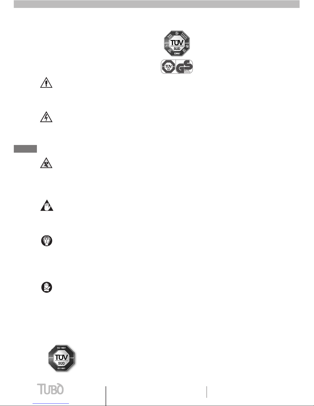
SAFETY
This sign is used in the manual to point out all
operations that must be strictly followed to guarantee
personal safety as well as the safety of others and the
central power unit.
HAZARD: this indicates that attention must
be paid in order to prevent events that could
cause serious accidents that harm people or
their health.
HAZARDS OF AN ELECTRIC NATURE: make sure
that the central power unit is connected with
the relative cable to a standard compliant
earthing system. Complete disconnect the
voltage from the central power unit for
maintenance operations.
CRUSHING HAZARD: when handling
and installing the central power unit it is
recommended to use suitable equipment for
lifting and securing it to prevent the central
power unit from falling accidentally.
HAZARD OF DAMAGING THE CENTRAL POWER
UNIT: follow the provided instructions for use
to prevent consequences that could damage
the central power unit.
INHALATION OF HARMFUL ELEMENTS AND
DUST: protect respiratory organs by using
protective masks when emptying the dust
containers and when replacing the filter
cartridge so the collected dust is not inhaled.
DUST SENSITIVITY: this means that hand
protection must be used to prevent harming
operators who are sensitive to the collected
dust.
Quality system
UNI EN ISO 9001
Environmental management
system
UNI EN ISO 14001
Product certication for the single-
phase power unit range for the
residential market sector, series:
STUDIO TS
CERTIFICATIONS
Aertecnica S.p.A is a company certified with:
IDENTIFICATION
This user and maintenance manual is an inherent part of
the central power unit:
SERIES: STUDIO TS
MODELS: TS1 - TS2 - TS4
MANUFACTURER
AERTECNICA S.p.A.
Via Cerchia di Sant’Egidio,760
47521 Cesena (FC) ITALY
Tel. +39 0547/637311
Fax +39 0547/631388
www.aertecnica.com
Technical Service
The Technical Service Centre can be contacted for all
technical problems and in order to request spare parts.
For all communications concerning the central power
unit, the user should always provide the following data:
central power unit model
serial number
year of manufacturing
date of purchase and a detailed description of the
discovered problems.
When replacing the central power unit’s spare parts it is
recommended to use original spare parts; AERTECNICA
declines all liability concerning decreased performance
or damage to the central power unit due to the use of
non-original spare parts.
3User and maintenance manual General information
General information
english
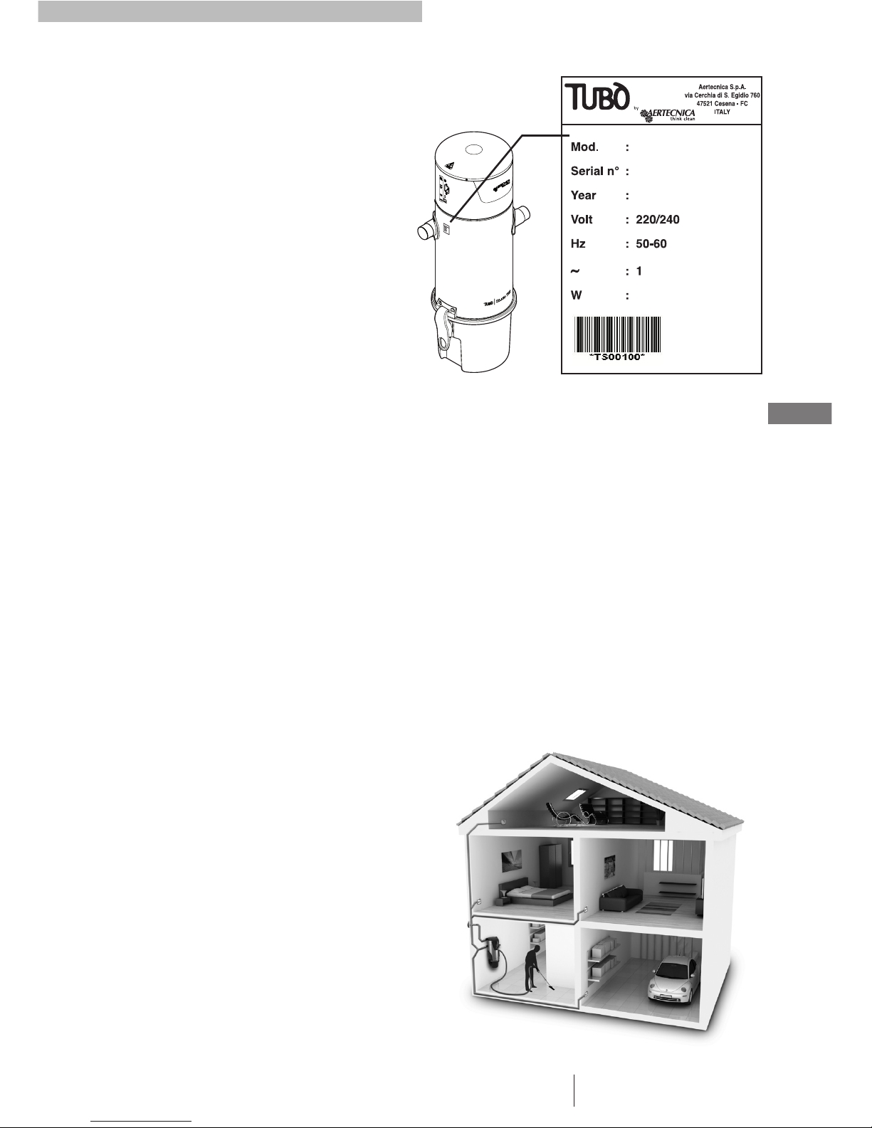
IDENTIFICATION PLATE
For these models, the identification plate is located on
the body of the central power unit as shown in the
figure.
The necessary identification data are:
model, serial number and year of manufacturing.
DESCRIPTION OF THE TUBÒ
VACUUM SYSTEM
The purchased central power unit is the main component
of TUBÒ, AERTECNICA’s advanced vacuum system.
The TUBÒ system consists of the central power unit,
vacuum sockets installed in the building’s walls, the
hose that is inserted in the vacuum sockets based on
the room to be cleaned and a set of cleaning accessories
suitable for all residential needs.
A network of plastic pipes installed under the floor and
in the walls of the building form the dust intake line
that is connected to the central power unit.
The collected dust reaches the central power unit; the
large dust particles fall into the collection container
whereas a filter cartridge retains the suspended dust;
the micro dust (invisible to the eye and not filtered
by the cartridge) is discharged outside through the
air exhaust line, guaranteeing home hygiene and
preventing the dust from recirculating in homes.
The system can reach all areas of the home, both
inside as well as outside depending on the position
of the vacuum sockets installed in the building. The
recommended hose is 9 m. long, which makes it possible
to cover a circular area of approx. 40 m2(a reduction
in the radius of the circumference is due to obstacles in
the room (furniture) that make it necessary for the tube
to follow a curved path).
The dust container must be emptied periodically (approx.
2-3 times a year; see paragraph CONTAINER EMPTYING).
The filter cartridge should be replaced with a new one
every 2-3 years (based on its use; see paragraph FILTER
CARTRIDGE REPLACEMENT).
The filter cartridge can be regenerated by washing it
periodically (based on its use; see paragraph FILTER
CARTRIDGE REGENERATION).
These timescales are approximate for normal vacuum
system use. In the case of intense use of the system
and a large amount of vacuumed dust, the timescale
will be shortened.
TS2
TS00100
2010
1600
General information
General information 4

english
PART DESCRIPTION
Legend
1 - Sound-proofed motor chamber
2 - Electric motor
3 - Motor air intake
4 - Dual right/left dust inlet
5 - Air Exhaust line (only TS4)
6 - Power supply
7 - Operation Signal input
8 - Green Led On: power unit on
9 - Green Led On: power unit running
!
"
#!
#$
#
%
$
$
##
#%
#"
#&
#'
#&
!
#(
#) &
*
'
(
STUDIO TS4 STUDIO TS2
10 - Fuse
11 - Filter cartridge
12 - Fixing Knob
13 - Fixing bracket
14 - Locks lever
15 - Cone conveyor
16 - Ergonomic handles
17 - Dust container
18 - Dust inlet closing cap
5User and maintenance manual General information
General information
english
TECHNICAL FEATURE
Model STUDIO TS1 STUDIO TS2 STUDIO TS4
Power supply Volt (Vac) 220/240 220/240 220/240
Motor power Watts (W) 1.260 1.600 1.650
Frequency HZ50/60 50/60 50/60
Motor rpm rpm 43.507 46.480 31.014
Turbine stages n° 112
SOFT START starting YES YES YES
Socket power supply Volt (Vcc) 12 12 12
Vacuum power Air Watts 504 653 690
Max. air ow rate m3/h 207 195 238
Max. vacuum mbar 270 313 320
Filter cartridge surface cm24000 8000 8000
Filter cartridge material POLYESTER POLYESTER POLYESTER
Dust container capacity litres 15 15 23
Height cm 64 90 103
Diameter cm 28 28 32
Weight kg 13 16 18
CMT800 Compatibility YES YES YES
CM8890 Remote Panel Kit
Compatibility YES YES YES
CM186 Wireless system
Compatibility YES YES YES
Right and left dust inlet YES YES YES
Right air exhaust YES1YES1YES
Noise dB 57 55,6 58
Silencer as standard equipment NO NO YES
1 Exhaust conveyor line with CM640 convey (Optional)
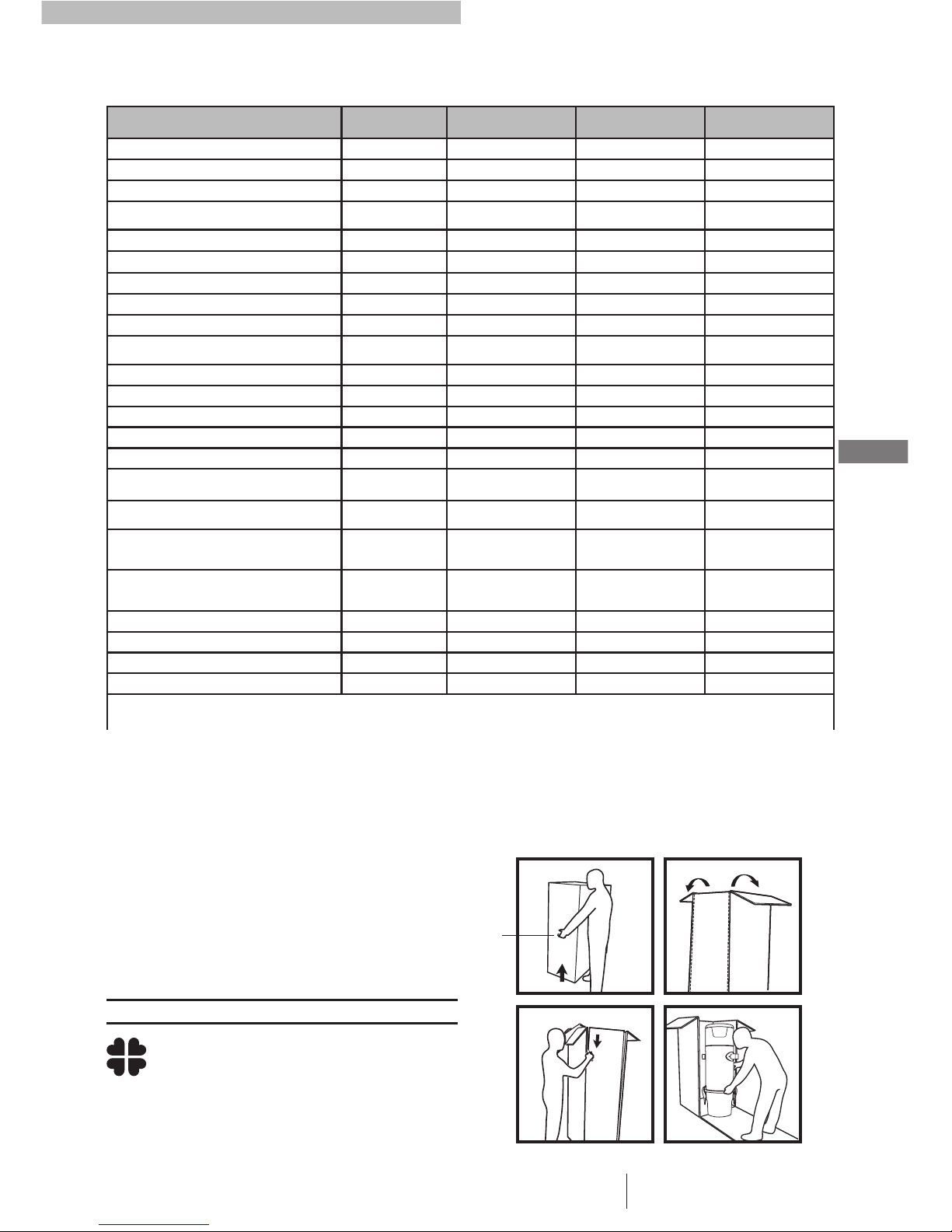
HANDLING THE PACKAGING
The central power unit is delivered inside cardboard
packaging to make it easier to transport.
It is recommended to not remove the packaging until
installation to prevent damaging it.
To lift and transport the central power unit, use the
handles positioned on the sides of the packaging (1).
The packaging elements that accompany
the central power unit upon delivery are
inert solid waste that must be disposed of
according to current applicable regulations.
NOTE
OPENING THE PACKAGING
When opening the central power unit packaging, follow
the instructions indicated on the sides of the cardboard
box.
#
General information
General information 6
english
E
A
B
E
A
D
C
FORESEEN USE
The central power unit was designed exclusively for
vacuuming dust or small sized solid bodies.
The dust container must be emptied each time that it
is filled.
The filter cartridge must be regenerated periodically
and must be replaced every 2-3 years or immediately
if it breaks.
When replacing spare parts, use original Aertecnica
spare parts.
INCORRECT USE
Use personal protection garments before
carrying out operations such as emptying
the dust container or replacing/cleaning the
ltering cartridge.
In order to guarantee proper operation of the central
power unit and to prevent the relative warranty
coverage from lapsing, follow the instructions provided
below:
Do not vacuum lighted cigarettes, hot embers or
burning material: these materials may cause a fire to
start that would damage the hoses and the central
power unit.
Do not vacuum cloths, rags, fabrics or textile material:
these materials could obstruct the hoses or damage the
central power unit .
Do not vacuum liquids, materials saturated with liquids
or very moist materials: these materials could cause
the electric system to short circuit, prevent the proper
passage of the dust or damage the sockets and the
central power unit.
Liquid can be vacuumed using a special accessory (art.
AP372; art. AP373).
Do not allow children to play with the vacuum sockets,
opening and closing them continuously or inserting
toys or solid items of unsuitable dimensions.
Do not vacuum the dust using multiple sockets at the
same time(Aertecnica produces central power units that
can be used by multiple operators at the same time in
the TRIFASE line).
Do not use the system with the central power unit
turned on without the filter cartridge inserted.
Do not block the air exhaust line.
Do not block the air sockets for electric motor cooling.
Do not use the cleaning accessories to vacuum parts
of the body.
Do not leave the central power unit powered when it is
not used for prolonged periods of time.
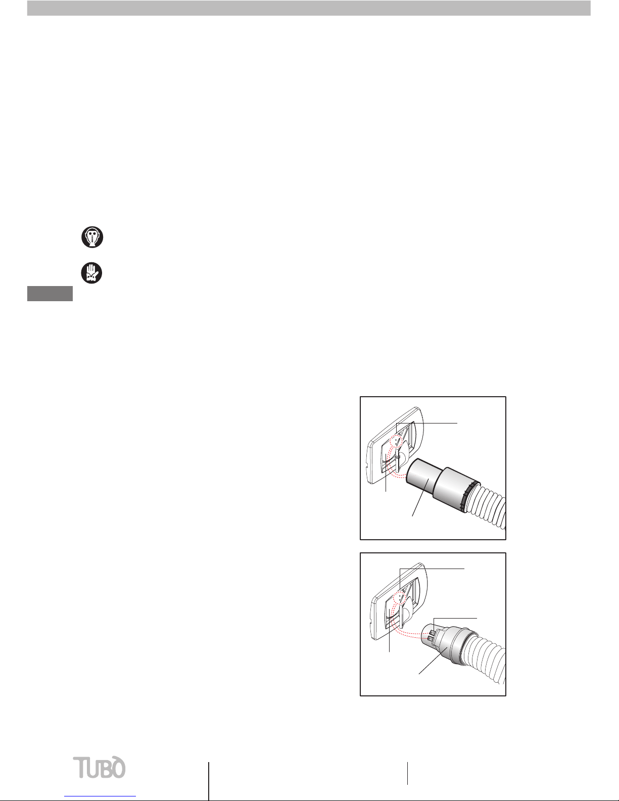
TURNING ON/OFF
Turning on the centralised vacuum system depends on
the type of hose and the installed vacuum socket model.
There are two types of hoses:
TYPE 1: hose with an activator union.
The central power unit turns on when the union (B) is
inserted in the vacuum socket (A).
TYPE 2: hose with a switch.
The central power unit is turned on using the switch on
the hose itself.
Insert the hose-socket union with the special plates (D)
in correspondence of the contacts (E) inside the socket.
To turn off the central power unit:
with the TYPE 1 hose, remove the hose from the vacuum
socket (A);
with the TYPE 2 hose, move the switch to the OFF
position.
TYPE 1
TYPE 2
7User and maintenance manual General information
General information
english
General information
General information 8
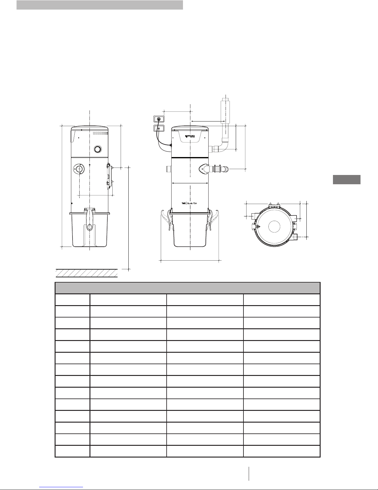
CENTRAL POWER UNIT POSITIONING
The central power unit is installed in service rooms (for
example, store-rooms, garages, cellars) that are aired
and protected from extreme temperature changes.
The installation area must be sufficiently spacious and
well-lit to be able to replace the filter cartridge and the
dust container.
STUDIO TS
INSTALLATION ALLOWANCES
(in mm.)
STUDIO TS1 STUDIO TS2 STUDIO TS4
A 143 298 360
B 400 400 350
C 330 330 260
D 280 280 320
E 250 250 280
F 314 321 370
G 124 124 200
H 650 900 1040
I 90 80 100
L 100 100 125
M 47 47 51
P 1500 1400 1400
Qoor level oor level oor level
F
G
D
C
A
P
Q
H
B
I
L
E
M
E
The 220/240 power supply line and the vacuum
socket consent line for activating the centralised
vacuum system must be prepared near the central
power unit.
The following table specifies the main reference allowances for
correct central power unit installation.
english
9User and maintenance manual Installation
Installation
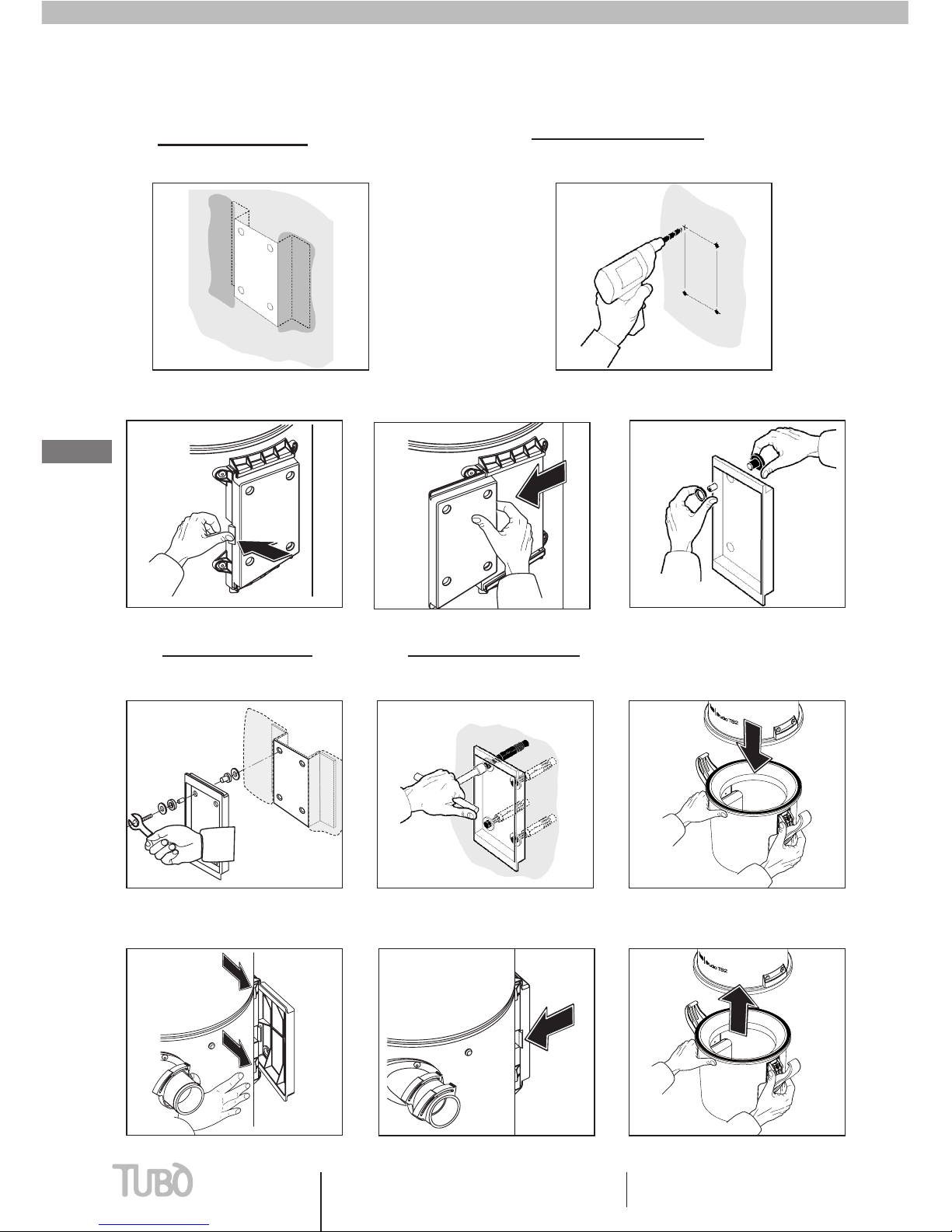
5A - WITH WALL STIRRUP
Fasten the bracket to the wall using
the supplied screws
5B - WITH SCREW ANCHORS
Fix the support using proper anchors (not
included)
6- Remove the dust container
8- Make sure the locking lever locks
in position
9- Refit the dust container7- Secure the power unit to the
support
BRACKET FASTENING
1A - WITH WALL STIRRUP
Fix the stirrup to the wall
1B - WITH SCREW ANCHORS M6 Ø12
Drill. Using a water level, check that the fixing is level
with the wall.
2- Shift the locking lever 4 -Fit the vibration blocks to the support
3- Pull off the support from the guides

english
Installation
10Installation
AIR EXHAUST CONNECTION
It is recommended to install an exhaust hose that is no
longer than 5 metres.
If the exhaust line is longer, use a hose with a diameter of
ø 63 or larger and install a silencer of a suitable diameter.
Always position the silencer near the exhaust grille.
AIR EXHAUST LINE COMPONENTS
1 - silencer ø100
2 - conical increase ø50F - ø82F
3 - exhaust grille ø82
4 - outlet hole ø82
All of the central power units have a dual dust inlet to
permit the connection of the socket line hose on both
sides of the central power unit, making installation
easier.
Select the most convenient central power unit dust inlet
to connect the dust inlet line
Check that the dust inlet not in use is closed. Place the
provided pressure cap (T).
SLEEVE MOUNTING
Assemble the rubber sleeve (M) on the dust inlet using
the two provided clamps (F) and connect it to the inlet
hose.
CONNECTION
DUST INLET LINE
ø 50
ø100
300 mm
ø 50
ø 82
ø 82
1
3
2
4
M
F
ø50 mm.
M
FF
T
M
FF
T

english
11 User and maintenance manual Installation
Installation
ELECTRICAL CONNECTION The central power unit electric power supply
system must be installed by qualied personnel
in compliance with current applicable
regulations.
The manufacturer declines all liability for poor
operation or damage to people and/or property
due to connection to a non-compliant electric
system
ELECTRICAL DANGER
If the power supply cable is damaged, it
must be replaced by AERTECNICA or its
Technical Service Centre or in any case by a
specialised technician in order to prevent all
electrical hazards.
DANGER OF ELECTROCUTION
Make sure that the electric line is dimensioned
to support the central power unit power and
check that the mains network corresponds to
the voltage specied on the identication plate.
NOTE
GENERAL COMPONENTS
1-
pre-wired sheathing 2x1 ø16 for socket line 1
2v
2-
electric junction box
3-
12v socket cable line
4- 12v signal input
5-
connection of 12v socket line with socket cable
1
10
2
3
8
9
5
7
6
4
CONNECTION OF THE CENTRAL POWER UNIT TO THE
POWER SUPPLY LINE
The power supply cable (8) with Schuko plug (7) for the
central power unit is supplied as standard equipment
with the central power unit .
CONNECTION OF THE CENTRAL POWER UNIT TO THE
SOCKET LINE
A socket cable connection (3) is supplied.
To make the socket line connection, wire the central
power unit connection cable as shown at the (5)
number.
6- 220/240V power outlet
7- Schuko plug
8- Electrical cable
9- Power supply
10 -Socket frame

english
MAINTENANCE
Careful maintenance prolongs the life-time of the
central power unit and guarantees better performance.
NOTE
Before starting with any maintenance
operation, disconnect the central power
unit from the power supply.
The central power unit must not be operated
without the lter cartridge inserted. Failure
to observe this rule could cause damage
to the motor that is not covered by the
warranty.
2 - Lift out the conveying ring
3 - Empty the dust container
4 - Reassemble the dust container paying attention to
the seal position (G) and close the handles.
CONTAINER EMPTYING
1 - Rotate both handles upwards simultaneously
andremove the dust container
GG
Installation
12Installation
english
13 User and maintenance manual Maintenance
Maintenance
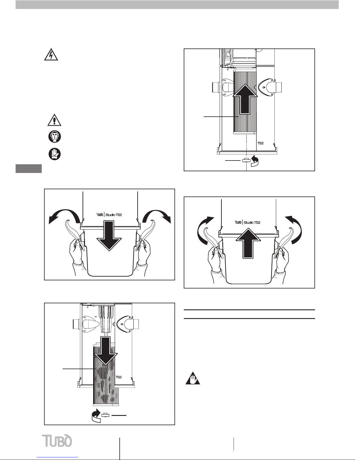
FILTER CARTRIDGE REPLACEMENT
ATTENTION
When carrying out this operation, it is
easy to come into contact with the dust
collected on the cartridge walls.
Before removing the lter cartridge, it is
recommended to wear suitable personal
protective garments.
1 - Open the dust container rotating the handles (M)
2 - Unscrew the knob (P) that fastens the cartridge (C)
and remove it from its housing
3 - Insert a new cartridge (N) and tighten the knob
completely (P).
4 - Rehook the dust container and close the handles (M).
It is recommended to replace the filter cartridge every
2-3 years.
This period may change depending on the degree of
system use.
Before starting with any maintenance
operation, disconnect the central power
unit from the power supply.
USE ONLY ORIGINAL AERTECNICA
SPARE PARTS
MM
P
C
P
N
MM
NOTE
The central power unit must not be operated without
the lter cartridge inserted. Failure to observe this
rule could cause damage to the central power unit
motor.

Maintenance
Maintenance
english
14
FILTER CARTRIDGE REGENERATION
(for all central power unit models)
Periodic filter cartridge regeneration improves overall
centralised vacuum system productivity.
With normal system use, the cartridge should be
checked every 4 months.
ATTENTION
When carrying out this operation, it is
easy to come into contact with the dust
collected on the cartridge walls.
Before removing the lter cartridge, it is
recommended to wear suitable personal
protective garments.
To effectively regenerate the saturated cartridge
and keep the centralised vacuum system operating,
it is recommended to insert a new filter cartridge
immediately, restart the system and vacuum the largest
dust particles from the saturated cartridge using the
system itself.
1 - Vacuum the dust collected on the saturated
cartridge walls using the system itself.
2 - After an initial brief cleaning, wash the filter
cartridge with a jet of water that is not too strong and
remove the dust that penetrated between the walls.
3 - Allow the cartridge to dry completely
4 - Make sure that there are not any tears or cuts on the
cartridge walls. In this case the damaged cartridge must
be replaced with a new one.
USE ONLY ORIGINAL AERTECNICA
SPARE PARTS
NOTE
The central power unit must not be operated without
the lter cartridge inserted. Failure to observe this
rule could cause damage to the central power unit
motor.
NOTE

english
15 User and maintenance manual Maintenance
Maintenance
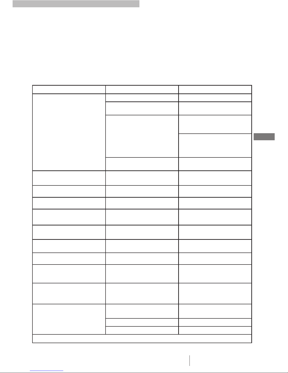
CENTRAL POWER UNIT DISPOSAL
(for all central power unit models)
At the end of its life cycle, the machine must be disposed of in
compliance with current applicable regulations.
The following table specifies the material with which the central
power unit is built.
IMPORTANT
The material listed below must be divided
and stored to be recycled or disposed of
in compliance with the environmental
regulations valid in the country of use.
TYPE OF MATERIAL PRESENCE IN SPECIFICS DISPOSAL
PLASTIC AND RUBBER
dust container 30% talc filled polypropylene
The regulations that
govern the disposal
and demolition of
the central power
unit, its components
and the possible
polluting material and
substances change
depending on the
country of nal use.
It is recommended to
contact authorised
organisations and
agencies and to
respect the current
applicable legal
regulations
cup, tangential openings polypropylene
under motor gasket thermoplastic rubber
motor ring nylon
filter cartridge poliestere + ABS
fixing bracket nylon 30% caricato vetro
antivibration bracket rubber
rubber sleeves SBR/NR rubber
fastening bracket nylon
adhesives PVC
hooks, handles nylon
gaskets mousse e pivilene
silencer polystyrene
GALVANISED COMPONENTS screws and rivets galvanized steel
WINDINGS electric motor and wiring copper
ELECTRICAL COMPONENTS
electronic card misc material
turbine motor misc material
led misc material
electric wires rcopper
socket cable line copper
schuko plug copper
METAL COMPONENTS upper body painted steel
clamps and pivots galvanized steel
PACKAGING
box cardboard
interpads cardboard
bags polyethylene
CENTRAL POWER UNIT INSPECTION
The general centralised vacuum system inspection must be done after the final assembly of all vacuum sockets and the selected central power unit.
CHECK 1
Activate the central power unit with all sockets closed, jumpering the 12V socket line.
Inserting the vacuum gauge in the dust inlet that is not used or in any vacuum socket, check the vacuum value obtained by the central power unit,
which will stop automatically after 15 seconds. Note the value that was reached(value 1).
Disconnect the tubing from the central power unit and insert a vacuum gauge in its place. Activate the central power unit jumpering the 12V
socket cable line; check the vacuum value obtained by the central power unit, which will stop automatically after 15 seconds. Note the value that
was reached (value 2).
Check that the difference between values 2 and 1 does not exceed 15 mbar.
If the value is higher, this means that there are leaks that must be found and repaired.
CHECK2
Compare value 2 with the vacuum value indicated in the technical features table for the central power unit model that was purchased.
Check that the difference between the two values does not exceed 10% of the table value.
If the value is higher, contact the Aertecnica Service Centre.
Maintenance
Maintenance
english
16
NOTE
the values indicated in the table refer to a power supply voltage of 240 V at 50 Hz. If the mains voltage is less, use the following formula:
every 10 volt = 10 mbar (example with the TP1 central power unit: 270 mbar at 240 V = 250 mbar at 220 V).
VACUUM TEST - FOR ALL CENTRAL POWER UNITS
1 -
Insert the hose in the furthest socket and activate the central power unit.
2 -
Insert the vacuum gauge (AT010) in the socket adjacent to the one occupied by the hose; if the vacuum value is correct (RANGE between 100 and
150 mbar) the hand will point to the green zone. In this case, the test is positive. Otherwise, contact the Aertecnica Service Centre.
PROBLEM CAUSE SOLUTION
THERE IS NO AIR INTAKE FROM
ALL THE SOCKETS
Power supply cable disconnected Connect the power supply cable
12V socket cable line not connected or
incorrectly connected
Connect the 12V socket cable line or
check the wiring
The motor overheated.
The motor temperature exceeded 80 °C.
Check if the air exhaust line is free or if
the two air exhaust openings are blocked.
Wait for the motor to cool down.
Make sure the filter cartridge is not
saturated. In this case, perform
maintenance. Wait for the motor to
cool down.
The dust container is not correctly
hooked
Rehook the container correctly.
THERE ISNO AIR INTAKE FROM
A SOCKET
The microswitch or the electric contacts
in a vacuum socket are damaged. Call a specialised technician.
LOW AMOUNT OF AIR INTAKE There is clogging in the system Call a specialised technician.
The filter cartridge is saturated Perform cartridge maintenance.
Multiple vacuum sockets are being used
at the same time on the system
The central power unit may only be used
by one operator at a time.
The dust container gasket is damaged or
out of position
Check the position of the dust container
gasket.
The air exhaust line is clogged Check if the air exhaust line is free or if
two air exhaust openings are blocked.
The hose is partially obstructed Free the obstruction from the hose.
The cap was not inserted correctly into
the dust inlet not being used in the
central power unit
Check that the dust inlet that is not
being used is closed with the special cap.
THE CENTRAL POWER UNIT ALWAYS
REMAINS ACTIVATEDEVEN WITH
THE SOCKETSCLOSED
The microswitch or the electric contacts
in a vacuum socket are damaged. Call a specialised technician.
THE LED OF THE POWER UNIT IS OFF
The central power unit power supply
cable is disconnected Call a specialised technician.
The protective fuse burnt out. Call a specialised technician..
The electronic card is defective Call a specialised technician.
Call a specialised technician for other causes that are not covered in this manual
TROUBLESHOOTING
This manual suits for next models
2
Table of contents
Other AERTECNICA Vacuum Cleaner manuals

AERTECNICA
AERTECNICA TUBO PERFETTO INOX TXA User manual

AERTECNICA
AERTECNICA ROBO TR800 User manual

AERTECNICA
AERTECNICA TUBO ROBO TR900L User manual

AERTECNICA
AERTECNICA TUBO FAST User manual

AERTECNICA
AERTECNICA TUBO CM188T User manual

AERTECNICA
AERTECNICA AP353PR Operator's manual

AERTECNICA
AERTECNICA TUBO ROBO ITR804 User manual

AERTECNICA
AERTECNICA AIRO TWIST User manual


