Aetina AX720 Series User manual

User Manual
NVIDIA Jetson Series Carrier board
Aetina AX720 Series

ii
Document Change History
Version
Date
Description
Authors
V1.0
2020/07/7
Initial Release.
Eric Chu
V1.1
2020/09/29
Update U555 component description.
Stany Tsai
V1.2
2021/01/19
Correct CN22 image.
Stany Tsai
V2.0
2022/04/02
Add information
Rick Chiu
V2.1
2022/7/26
Correction for J509 Pin define (Pin7,9)
Jia Tsai

iii
Contents
1. Introduction..............................................................................................................................................................1
1.1 Features ..................................................................................................................................................1
2. Ordering information ...............................................................................................................................................2
2.1 Model information..................................................................................................................................2
2.2 Packing list ..............................................................................................................................................2
3. Board Specifications.................................................................................................................................................3
4. Product Overview.....................................................................................................................................................4
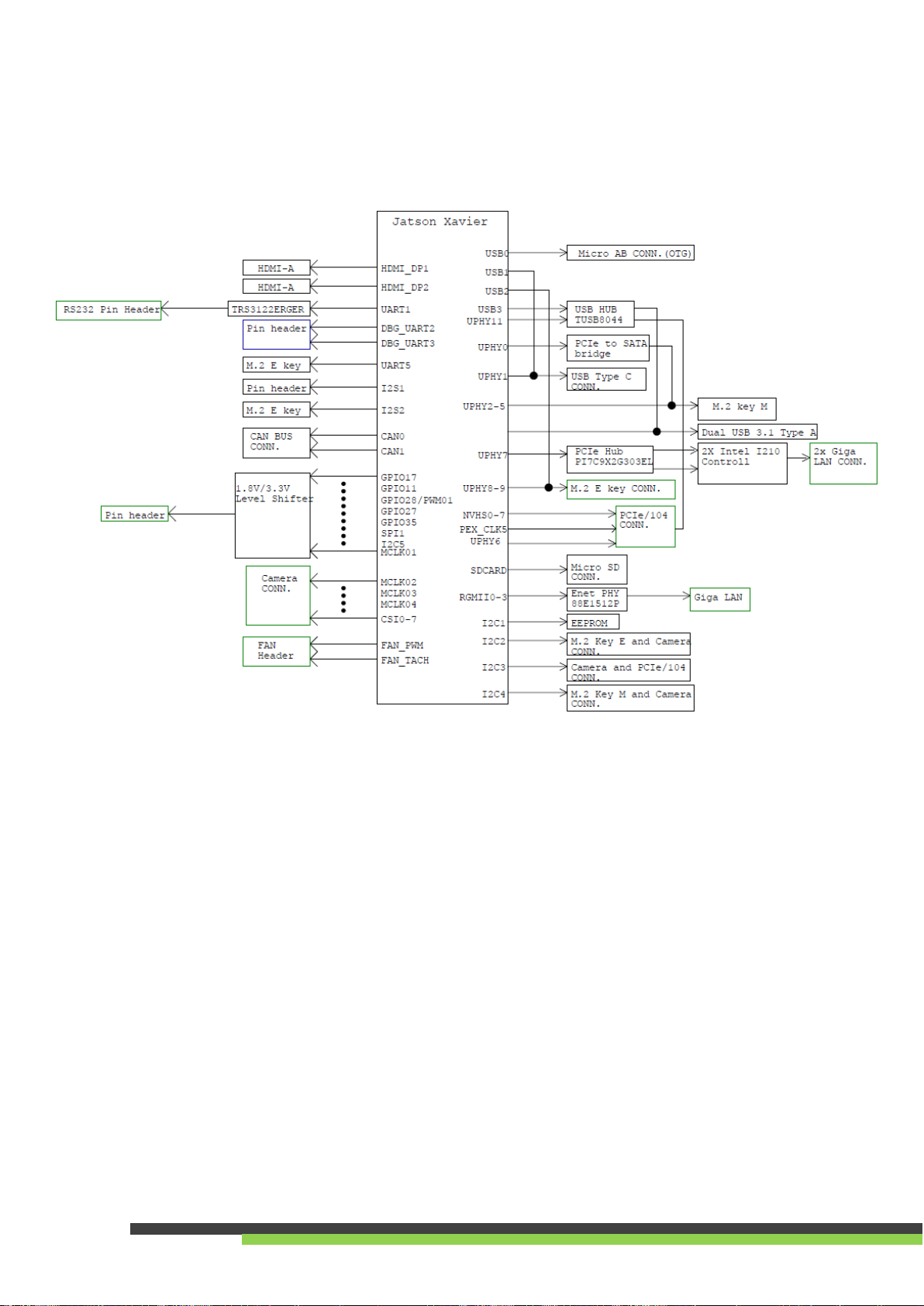
4.1 Block Diagram .........................................................................................................................................4
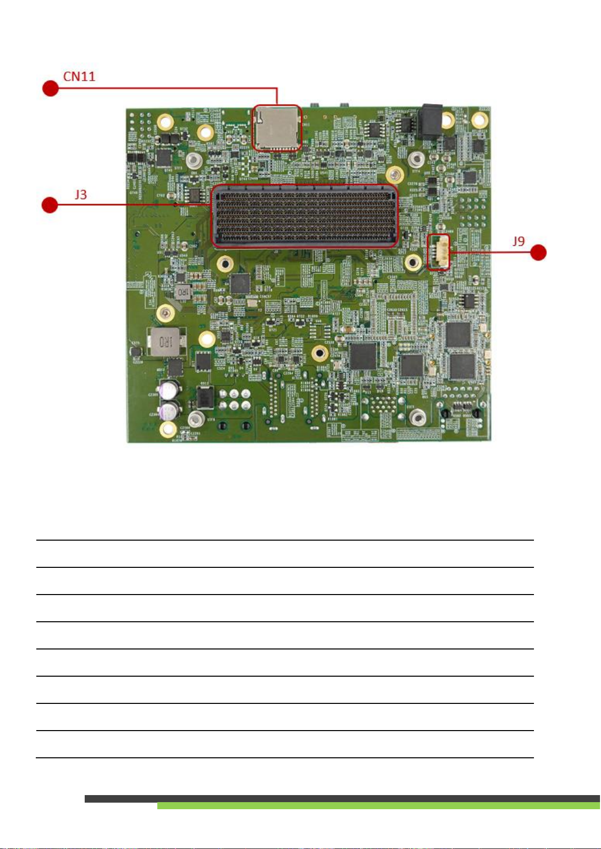
4.2 Connectors, LEDs, and Switches Locations.............................................................................................5
4.3 Connectors, LEDs, and Switches Description..........................................................................................6
4.4 Connectors and Pin-outs.........................................................................................................................7
5. Power Consumption...............................................................................................................................................18
6. Mechanical Dimensions .........................................................................................................................................19

1
1. Introduction
AX720 carrier supports NVIDIA® Jetson™ AGX Xavier series modules and you can quickly
emulate the functionality of your desired end product for software development and
hardware verification.
To build a functional prototype of your target system you will need:
•NVIDIA Jetson AGX Xavier 32GB/64GB module
•Carrier board
•Power adaptor
1.1 Features
Here are the AX720 carrier board features below.
•Specifically designed for high performance and low-power envelope AI computing
Additional driver to support Embedded peripheral modules for multiple I/O
expansion capability.
•On-board 2x HDMI, 1x M.2 M Key, 1x M.2 E Key and 3x RJ45 to support rich
multimedia.
•Extended temperature range -40°C to 85°C.
•Suitable for general robotics, UAV, industrial inspection, medical imaging and deep
learning.
•1x 120pin board to board connector to support MIPI CSI-II adapter.

2
2. Ordering information
2.1 Model information
Here is the model information below.
Model Name
Description
AX720-STD-AN00
AX720 carrier board, standard temp -40°C to +85°C
AX720-X32-FN02
AX720 + 32G XavierTM Module + FAN + Cable Kit + Power Adapter and US Power
Cord -25°C to +80°C
AX720-X32-FN03
AX720 + 32G XavierTM Module + FAN + Cable Kit + Power Adapter and EU Power
Cord -25°C to +80°C
AX720-X32-BN70
AX720 + Chassis + 32G XavierTM Module + FAN+ Power Adapter + Cable -20~70°C
AX720-X64-FN02
AX720 + 64G XavierTM Module + FAN + Cable Kit + Power Adapter and US Power
Cord -25°C to +80°C
AX720-X64-FN03
AX720 + 64G XavierTM Module + FAN + Cable Kit + Power Adapter and EU Power
Cord -25°C to +80°C
AX720-X64-BN70
AX720 + Chassis + 64G XavierTM Module + FAN+ Power Adapter + Cable -20~70°C
2.2 Packing list
Part No.
Description
31-080000-0002
AX720 Cable kit (CAN bus / UART / RS232 / Front panel / GPIO / I2C)
53-0F0000-0004
100-240V 120W Power Adapter
32-010000-0005
or
32-010000-0006
US or EU POWER CORD
53-0MSBTG-0000
Dual Isolated GbE LAN board with cable
*AX720-X32/X64-BN70 is not supported

3
3. Board Specifications
Specifications
Description
Module Compatibility
Nvidia Jetson AGX Xavier 32GB / 64GB
GPU
Jetson AGX Xavier 32GB/64GB:
-Nvidia VoltaTM, 512 CUDA cores/64 Tensor cores.
CPU
Jetson AGX Xavier 32GB/64GB:
-HMP Quad ARM® V8.2 CPU/2MB L2/4MB L3
Memory
-32GB/64GB 256-Bit LPDDR4x
Display
-2x HDMI 2.0b Type A
Audio
-HDMI Integrated / I2S
LAN
-3x Gigabit Ethernet(1x on board and 2x on extension board)
*AX720-X32/X64- BN70 only support 1 Gigabit Ethernet
USB
-2x USB3.2 Gen1 Type A
-1x USB3.2 Gen1 TypeC
-1x USB2.0 Micro AB OTG
Expansion
-1x M.2 M-key 2280 (NVMe)
-1x M.2 E-key 2230
-1x Micro SD
UART
-3x UART
RS232
-1x RS232
I2C/SPI
-1x I2C
-1x SPI
GPIO
-5x GPIO
CAN Bus
-2x CAN Bus
Power Input
-1x 6pin Power Connector DC-in 9V~20V
Dimension
-131 x 120 x 30.5mm (WxDxH)
Net weight
-140g
Vibration
-
Shock
-
Operating Temperature
--40°C to + 85°C
Storage Temperature
--40°C to + 85°C
Certification
-CE/FCC
OS Support
-Ubuntu 18.04

4
4. Product Overview
4.1 Block Diagram
Here is the block diagram below.

5
4.2 Connectors, LEDs, and Switches Locations

6
4.3 Connectors, LEDs, and Switches Description
J3
Jetson AGX XavierTM module connector
CN3 / CN25
HDMI 2.0b Type-A connector
J1
M.2 M-Key 2280 connector, support PCIe/mSATA function device
J505
M.2 E-Key 2230 connector, support PCIe/USB2.0 function device
CN8
USB3.2 Gen1 Type-A x2
J509
120 pin board to board connector for MIPI CSI-2
CN7
USB2.0 Micro AB, support OTG function only
CN4
USB3.2 Gen1 Type-C

7
CN24
RJ45 connector, support 10/100/1000M Ethernet
J514
Dual RJ45 Extension board connectors
U555
Extension slot
*(Pinout is not compatible with PCIe/104)
CN16
Support I2S function
CN17
Support SPI function
CN21
Support CAN BUS function
CN26
I2C / Auto Power On (pin 1-2)
CN6
UART x1 / GPIO x5 / RS232 x1
J513
Front Panel
CN22
DC output
CN5
6 pins Power input connector
CN2
Debug UART
S502
Reset Button
S503
Recovery Button
J9
5V Fan connector
SW1
To enable M.2 B key function by connecting ADM2B-720-NN05, please
configure 1&2 to ON to supply 12V power to U555
*USB3.2 Gen1 Type A[CN8] will downgrade to USB2.0 speed
LED
Power Status LED
4.4 Connectors and Pin-outs
Here are the connectors and Pin-outs information of AX720 carrier board below.
•Jetson AGX XavierTM module connector
Location
J3
Type
AGX XavierTM connector
Pin definition
Refer to NVIDIA Jetson AGX Xavier™
System-on-Module datasheet

8
•HDMI 2.0b Type-A connector
Location
CN3,CN25
Type
HDMI vertical connector
Pin definition
Refer to HDMI Type-A Standard
•M.2 M-Key connector (NVME)
Location
J1
Type
M.2 M-Key 2280
Pin definition
Refer to M.2 M-Key Standard
Description
Support PCIe/mSATA function device
•M.2 E-Key connector
Location
J505
Type
M.2 E-Key 2230
Pin definition
Refer to M.2 E-Key Standard
Description
Support PCIe/USB2.0 function device
•Dual USB3.2 Gen1 Type-A connector
Location
CN8
Type
Type-A USB connector
Pin definition
Refer to USB Standard

9
•120 pin board to board connector for MIPI CSI-2
Location
J509
Type
QSH 120 pin connector
Pin No.
Description
Pin No.
1
CSI_0_D0_P
CSI1_D0_P
2
3
CSI_0_D0_N
CSI1_D0_N
4
5
GND
GND
6
7
CSI_0_CLK_P
CSI1_CLK_P
8
9
CSI_0_CLK_N
CSI1_CLK_N
10
11
GND
GND
12
13
CSI0_D1_P
CSI1_D1_P
14
15
CSI0_D1_N
CSI1_D1_N
16
17
GND
GND
18
19
CSI2_D0_P
CSI3_D0_P
20
21
CSI2_D0_N
CSI3_D0_N
22
23
GND
GND
24
25
CSI2_CLK_P
CSI3_CLK_P
26
27
CSI2_CLK_N
CSI3_CLK_N
28
29
GND
GND
30
31
CSI2_D1_P
CSI3_D1_P
32
33
CSI2_D1_N
CSI3_D1_N
34
35
GND
GND
36
37
CSI4_D0_P
CSI6_D0_P
38
39
CSI4_D0_N
CSI6_D0_N
40
41
GND
GND
42
43
CSI4_CLK_P
CSI6_CLK_P
44
45
CSI4_CLK_N
CSI6_CLK_N
46
47
GND
GND
48
49
CSI4_D1_P
CSI6_D1_P
50
51
CSI4_D1_N
CSI6_D1_N
52
53
GND
GND
54
55
DVDD_CAM_LV
DVDD_CAM_LV
56
57
58
59
CSI5_D0_P
CSI7_D0_P
60
61
CSI5_D0_N
CSI7_D0_N
62
63
GND
GND
64
65
CSI5_CLK_P
CSI7_CLK_P
66

10
67
CSI5_CLK_N
CSI7_CLK_N
68
69
GND
GND
70
71
CSI5_D1_P
CSI7_D1_P
72
73
CSI5_D1_N
CSI7_D1_N
74
75
I2C_GP3_CLK
NC
76
77
I2C_GP3_DAT
NC
78
79
GND
GND
80
81
AVDD_CAM
AVDD_CAM_ 2V8
82
83
NC
84
85
NC
NC
86
87
I2C_GP2_CLK
CAM1_MCLK03
88
89
I2C_GP2_DAT
GPIO15_CAM1_
PWDN
90
91
CAM0_MCLK02
GPIO16_CAM1_RST
92
93
CAM0_PWDN
CAM2_MCLK04
94
95
CAM0_RST
NC
96
97
NC
NC
98
99
GND
GND
100
101
DVDD_CAM_ IO
VDD_1V8
102
103
NC
NC
104
105
I2C_GP4_CLK
NC
106
107
I2C_GP4_DAT
VDD_3V3
108
109
NC
110
111
NC
NC
112
113
NC
NC
114
115
GND
GND
116
117
NC
VDD_3V3
118
119
GPIO25_VDD_
SYS_EN
120
•USB2.0 Micro USB (OTG only)
Location
CN7
Type
Micro AB USB connector
Pin definition
Refer to Micro USB standard

11
•USB3.2 Gen1 Type-C connector
Location
CN4
Type
Type-C USB connector
Pin definition
Refer to USB Type-C standard
•10/100/1000 Ethernet connector
Location
CN24
Type
RJ-45 connector
Pin definition
Refer to Ethernet standard
•Dual RJ45 Extension board connectors
Location
J514
Type
Wafer connector
Pin definition
N/A
To use the dual RJ45 Ethernet extension function, please connect to
Dual Isolated GbE LAN board as below.

12
•Extension slot
Location
U555
Type
PCIe /104 connector socket
Pin definition
N/A
Note: U555 only support Aetina dual 10G Ethernet extension board and the
information link is listed below.
Link: https://www.aetina.com/peripherals-detail.php?i=96
•Pin header for I2S
•Pin header for SPI
Location
CN16
Type
Pin header
Pin No.
Description
Pin No.
1
MCLK01_1V8
I2S1_FS_1V8
2
3
I2S1_DOUT_1V8
I2S1_DIN_1V8
4
5
SYS_RST_IN#
AUDIO_CDC_IRQ
6
7
I2S1_SCLK_1V8
GND
8
Location
CN17
Type
Pin header
Pin No.
Description
Pin No.
1
SPI1_SCK_3V3
N/A
2
3
SPI1_MISO_3V3
SPI1_MOSI_3V3
4
5
SPI1_CS0_3V3
SPI1_CS1_3V3
6
7
VDD_3V3
GND
8

13
•CAN Bus Connector
•Pin header for I2C / Auto Power On
Location
CN21
Type
Wafer connector
Pin No.
Description
Pin No.
1
CAN0H
CAN1H
2
3
CAN0L
CAN1L
4
5
CAN1_STBY
CAN1_STBY
6
7
CAN0_EN
CAN1_EN
8
9
CAN_WAKE
GND
10
Location
CN26
Type
Pin header
Pin No.
Description
Pin No.
1
AC OK
GND
2
3
SOC_LED+
GND
4
5
+3V3
I2C_GP1_DAT_3V3
6
7
GND
I2C_GP1_CLK_3V3
8

14
•MISC I/O Connector
•Front Panel
Note: To power on the system, short-circuit Power ON (pin 1) and GND0 (Pin 2).
Location
CN6
Type
Wafer connector
Pin No.
Description
Pin No.
1
UART0_RXD_HDR_3V3
RS232_RXD
2
3
UART0_TXD_HDR_3V3
RS232_TXD
4
5
UART0_RTS_HDR_3V3
RS232_RTS
6
7
UART0_CTS_HDR_3V3
RS232_CTS
8
9
GND0
GND1
10
11
GPIO0
GND2
12
13
GPIO1
GND3
14
15
GPIO2
GND4
16
17
GPIO3
GND5
18
19
GPIO4
GND6
20
Location
J513
Type
Wafer connector
Pin No.
Description
Pin No.
1
Power On
GND0
2
3
Reset
GND1
4
5
Recovery
GND2
6
7
Sleep
GND3
8
9
LED+
LED-
10

15
•DC output
•Power input connector
•Pin header for debug UART
Location
CN22
Type
Wafer connector
Pin No.
Description
Pin No.
1
VCC_SRC
VCC_SRC
2
3
GND
GND
4
Location
CN5
Type
6-pin male connector
Pin No.
Description
Pin No.
1
VCC_SRC
GND
2
3
VCC_SRC
GND
4
5
VCC_SRC
GND
6
Location
CN2
Type
Pin header
Pin No.
Description
1
UART3_RXD_HDR3V3
2
UART3_TXD_HDR3V3
3
GND

16
•Reset button
•Recovery button
•5V Fan Connector
•SW1
Location
S502
Type
Tact switch
Location
S503
Type
Tact switch
Location
J9
Type
Wafer connector
Pin No.
Description
1
GND
2
VDD_5V
3
FAN_TACH_CON
4
FAN_PWM_Q
Location
SW1
Description
To enable M.2 B key function by
connecting ADM2B-720-NN05,
please configure 1&2 to ON to
supply 12V power to U555
*USB3.2 Gen1 Type A[CN8] will
downgrade to USB2.0 speed

17
•
•LED Indicator
Location
LED
Description
Power Status
Power On: GREEN LED
Power Off: Off
This manual suits for next models
10
Table of contents
Other Aetina Carrier Board manuals