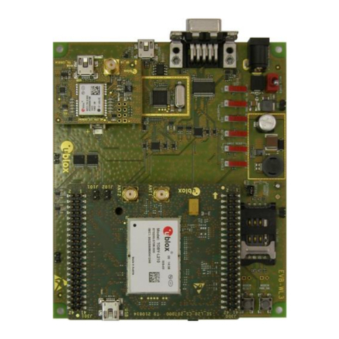
EVK-NINA-W1/EVK-NINA-B2 - User guide
UBX-17011007 - R08 Contents Page 3 of 27
C1-Public
Contents
Document information................................................................................................................................2
Contents ..........................................................................................................................................................3
1Product description ..............................................................................................................................4
1.1 Overview........................................................................................................................................................ 4
1.2 Kit includes ...................................................................................................................................................6
1.2.1 EVK-NINA-B221 and EVK-NINA-W1x1 .......................................................................................... 6
1.2.2 EVK-NINA-B222 and EVK-NINA-W1x2 .......................................................................................... 6
1.2.3 EVK-NINA-W1x6 ................................................................................................................................. 6
1.3 I/O allocation................................................................................................................................................. 7
1.4 Jumper description .................................................................................................................................... 8
1.4.1 Default jumper configuration.........................................................................................................10
1.4.2 RMII to PHY jumper configuration.................................................................................................10
1.5 LEDs.............................................................................................................................................................11
1.5.1 RGB-LED jumper configuration .....................................................................................................11
1.6 Connectors .................................................................................................................................................12
1.7 Buttons........................................................................................................................................................12
1.8 Configuration options ..............................................................................................................................13
1.8.1 UART ...................................................................................................................................................13
1.8.2 Power supply......................................................................................................................................13
2Setting up the evaluation board.................................................................................................... 14
2.1 EVK without software (open CPU).........................................................................................................14
2.2 EVK with u-blox connectivity software.................................................................................................14
2.2.1 Starting up .........................................................................................................................................15
2.2.2 Getting the latest software ............................................................................................................15
Appendix ....................................................................................................................................................... 16
ALayout EVK-NINA-W1x1, -W1x2 and EVK-NINA-B221, -B222 ........................................... 16
BLayout EVK-NINA-W1x6 .................................................................................................................. 16
CSchematic drawing EVK-NINA-W1x1, -W1x2 and EVK-NINA-B221, -B222................... 17
DSchematic drawing EVK-NINA-W1x6.......................................................................................... 21
EGlossary ................................................................................................................................................. 25
Related documents ................................................................................................................................... 26
Revision history.......................................................................................................................................... 26
Contact.......................................................................................................................................................... 27
