Afriso EURO-INDEX D0 User manual
Mess-, Regel- und
Überwachungsgeräte
für Haustechnik,
Industrie und Um
weltschutz
Lindenstraße 20
74363 Güglingen
Telefon
+49 7135 102-0
Service
+49 7135-102-211
Telefax
+49 7135-102-147
info@afriso.de
www.afriso.com
+Read instructions before using product!
+Observe all safety information!
+Keep instructions for future use!
02.2017 0
854.001.0336
Operating instructions
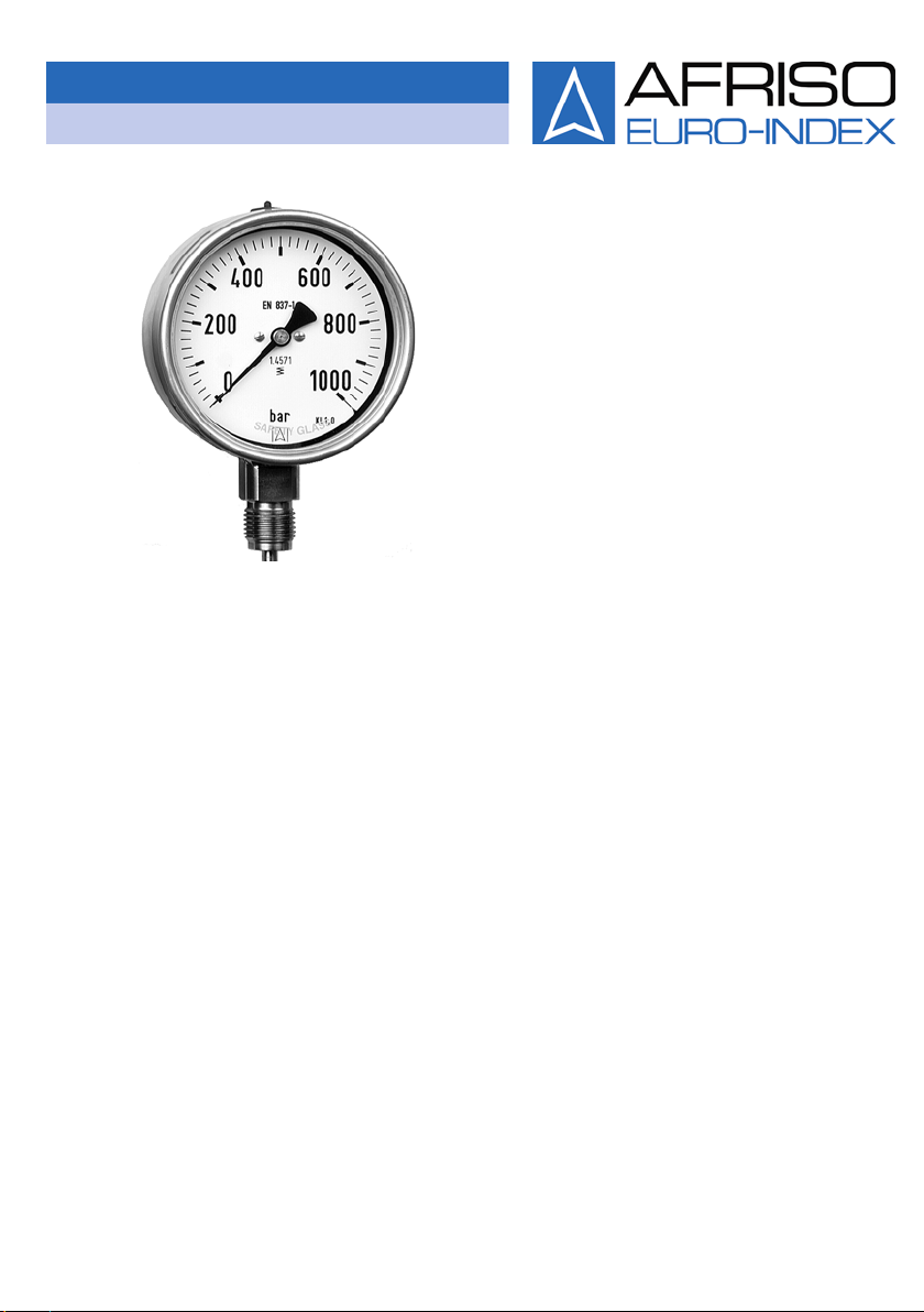
Bourdon tube pressure gauges
Capsule pressure gauges
Diaphragm pressure gauges
Spring diaphragm pressure gauge for differential
pressure
D0, D1, D2, D3, D4, D5, D6, D7, D8, D9
Nominal size: 40, 50, 63, 80, 100, 160, 250

2 Bourdon tube, capsule, diaphragm, spring diaphragm pressure gauges
Table of contents
1This instruction manual............................................................................................4
1.1 Precautions ..................................................................................................4
2Safety.......................................................................................................................5
2.1 Intended use.................................................................................................5
2.2 Predictable incorrect application..................................................................6
2.3 Safe handling ...............................................................................................7
2.4 Staff qualification..........................................................................................7
2.5 Modifications to the product .........................................................................7
2.6 Usage of spare parts and accessories.........................................................8
2.7 Liability information ......................................................................................8
3Product description..................................................................................................9
3.1Measuring principle Bourdon tube pressure gauge.....................................9
3.2 Measuring principle capsule type pressure gauge.....................................10
3.3 Measuring principle diaphragm pressure gauge........................................10
3.4 Measuring principle spring diaphragm pressure gauge (differential
pressure)....................................................................................................10
4Selection criteria....................................................................................................10
4.1 Range.........................................................................................................11
4.2 Properties of the media..............................................................................11
4.3 Ambient conditions.....................................................................................12
4.4 Overload.....................................................................................................13
4.5 Accuracy classes .......................................................................................13
4.6 Connection.................................................................................................14
4.7 Nominal sizes.............................................................................................14
4.8 Cleanliness.................................................................................................14
5Technical specifications.........................................................................................15
5.1 Approvals, tests and conformities..............................................................20
6Transport and storage...........................................................................................21
7Mounting and commissioning................................................................................21
7.1 Connection thread......................................................................................24
7.2 Measurement arrangements......................................................................25
7.3 Mounting position.......................................................................................26
7.4 Connection types .......................................................................................27
7.5 Mounting types...........................................................................................28
7.6 Pressure tap piece .....................................................................................29
7.7 Measuring line............................................................................................29
7.8 Commissioning the product........................................................................30

Bourdon tube, capsule, diaphragm, spring diaphragm pressure gauges 3
8Operation...............................................................................................................32
8.1 Dismounting the pressure gauge...............................................................32
9Additional equipment.............................................................................................33
9.1 Shut-off unit................................................................................................33
9.2 Pressure gauge holder...............................................................................33
9.3 Siphons ......................................................................................................34
9.4 Chemical seals...........................................................................................34
9.5 Overpressure safety devices......................................................................34
9.6 Pressure gauge with maximum pointer......................................................35
9.7 Electrical contacts ......................................................................................35
10 Type code – design numbers................................................................................38
11 Maintenance..........................................................................................................39
12 Decommissioning, disposal...................................................................................40
13 Returning the device..............................................................................................41
14 Spare parts and accessories.................................................................................41
15 Warranty ................................................................................................................41
16 Copyright ...............................................................................................................41
17 Customer satisfaction............................................................................................42
18 Addresses..............................................................................................................42
19 Appendix................................................................................................................43
19.1 EU Declaration of Conformity.....................................................................43
19.2 Information on the Pressure Equipment Directive .....................................44
This instruction manual
4 Bourdon tube, capsule, diaphragm, spring diaphragm pressure gauges
1 This instruction manual
This instruction manual is part of the product.
Read this manual before using the product.
Keep this manual during the entire service life of the product
and always have it readily available for reference.
Always hand this manual over to future owners or users of the
product.
1.1 Precautions
WARNING
WORD
Type and source of the hazard are shown here.
Precautions to take in order to avoid the hazard are shown here
.
Warning word Meaning
WARNING Possibly imminent danger!
Failure to observe the information may result in
death or severe injuries.
CAUTION Dangerous situation!
Failure to observe the information may result in
minor or severe injuries as well as damage to
property.

Safety
Bourdon tube, capsule, diaphragm, spring diaphragm pressure gauges 5
2 Safety
2.1 Intended use
Bourdon tube pressure gauges
Bourdon tube pressure gauges may only be used to display the
pressure of media which are not highly viscous and which do not
crystallize.
Bourdon tube pressure gauges NS50 with inductive contact
(RF50ExIK1.2/ RF50IK1.2 - D302/D312) are additionally suitable for
the generation of signals within the given adjustment range. These
bourdon tube pressure gauges must always be operated in conjunc-
tion with a suitable isolating switching amplifier (for example, Turck,
MK13-P-EX0/24V).
Bourdon tube pressure gauges with clamp chemical seal (Tri-Clamp,
ISO 2852: RF63Ch-D9xx/RF100E-D9xx with MD60 1½"/MD60 2")
are additionally suitable for highly viscous, perishable and hot media.
These Bourdon tube pressure gauges are particularly suitable for
use in the food and beverages industry, for example, for milk and
dairy products.
Capsule pressure gauges
Capsule type pressure gauges may only be used to display the pres-
sure of dry, gaseous media.
Diaphragm pressure gauges
Diaphragm pressure gauges may only be used to display the pres-
sure of high-viscosity or crystallising media.
Spring diaphragm pressure gauge
Spring-diaphragm pressure gauges may only be used for differential
pressure measurement with low differential pressure and high static
pressure for gaseous and liquid media which are not highly viscous
and not corrosive. Particularly suitable for monitoring filters, pumps
and pipe systems.

Safety
6 Bourdon tube, capsule, diaphragm, spring diaphragm pressure gauges
Media
The fluids used must be compatible with the materials of the product
under the specific measuring conditions (for example, temperature,
atmosphere, immunity of the material against the measured fluid,
etc.) and which do not cause chemical reactions.
•Intended operation as per EN 837-1/-3
•No hot media with temperatures of more than 70 °C in the pres-
sure gauge. Take into account the compression heat that is
generated in the case of rapid pressure changes of gases.
•The pressure gauge is neither subjected to pressure surges nor
to pressure fluctuations.
Pressure gauges with switching contacts may only be used in certi-
fied intrinsically safe circuits as per EN 60079-11.
Any use other than the application explicitly permitted in this instruc-
tion manual is not permitted.
2.2 Predictable incorrect application
The pressure gauges must never be used in the following cases:
•Measurement of pressure exceeding the full scale value of the
pressure gauge
•Operation outside of the specified temperature range
•Use as a part of a safety system to protect against exceeding
permissible limit values (equipment parts with a safety-related
function)
•If used in hazardous areas / Ex zones: operation outside of the
specified intrinsically safe limit values

Safety
Bourdon tube, capsule, diaphragm, spring diaphragm pressure gauges 7
2.3 Safe handling
WARNING
Injury due to escaping fluids or bursting parts as
a result of
leaks or bursting of pressurised parts
Use Bourdon tube safety pressure gauges with blow-out (for
example, blow-out back).
As per EN 837, liquid-filled pressure gauges must have a blow-out
device (version S1, S2 or S3).
Pressure gauges for oxygen and acetylene must be safety pressure
gauges (version S2 or S3 as per EN 837-1 or pressure gauge as per
ISO 5171). All wetted parts must comply with EN 29539 must be free
from oil and grease. Only lubricants suitable for oxygen at maximum
operating pressure may be used. The pressure gauges must never
be exposed to humidity.
Pressure gauges with glycerine filling must not be used for oxygen or
other oxidising process fluids. High-concentration fluorine liquids and
chlorinated liquids (for example, halocarbon) are suitable for such
applications.
You must observe all pertinent directives and guidelines in the case
of refrigerating systems, compressors, etc. as well as hazardous
substances such as
•Oxygen
•Acetylene
•Flammable substances
•Explosive substances
•Toxic substances
After an external fire, measured fluid can escape, in particular at
soft solder connections. Verify and, if necessary, replace all
products before re-commissioning the system.
2.4 Staff qualification
The product may only be mounted, commissioned, operated, main-
tained, decommissioned and disposed of by qualified, specially
trained staff.
Electrical work may only be performed by trained electricians and in
compliance with all applicable local and national directives.
2.5 Modifications to the product
Changes or modifications made to the product by unauthorised per-
sons may lead to malfunctions and are prohibited for safety reasons.

Safety
8 Bourdon tube, capsule, diaphragm, spring diaphragm pressure gauges
2.6 Usage of spare parts and accessories
Usage of unsuitable spare parts and accessories may cause dam-
age to the product.
Use only genuine spare parts and accessories of the manufac-
turer.
2.7 Liability information
The manufacturer shall not be liable in any form whatsoever for
direct or consequential damage resulting from failure to observe the
technical instructions, guidelines and recommendations.
The manufacturer or the sales company shall not be liable for costs
or damages incurred by the user or by third parties in the usage or
application of this product, in particular in case of improper use of the
product, misuse or malfunction of the connection, malfunction of the
product or of connected products. The manufacturer or the sales
company shall not be liable for damage whatsoever resulting from
any use other than the use explicitly permitted in this instruction
manual.
The manufacturer shall not be liable for misprints.
Product description
Bourdon tube, capsule, diaphragm, spring diaphragm pressure gauges 9
3 Product description
3.1 Measuring principle Bourdon tube pressure gauge
Bourdon tube pressure gauges contain measuring elements (Bour-
don tubes) which are deformed if pressure is applied. This motion is
transmitted to a movement.
Bourdon tubes are tubes with a oval cross-section, bent into a circle.
The pressure to be measured acts on the inside of the tube so that
the oval cross-section approximates a circular shape. The bending of
the Bourdon tube causes ring tension which bends the tube open.
The loose tube end performs a movement which is a measure of the
pressure.
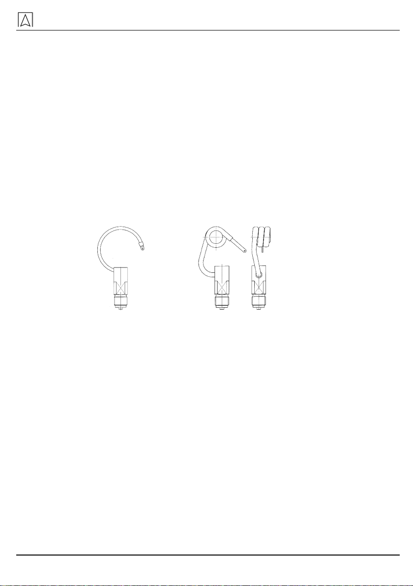
Circular tubes with an angle of 270° are typically used for pressures
of up to 60 bar; for greater pressures, the tubes with several helical
windings are used.
Fig. 1: Circular tube Fig. 2: Helical tube
The Bourdon tubes usually consist of copper alloys or alloyed steel.
Because of their sturdiness and the easy handling, the Bourdon tube
pressure gauge is the most commonly used pressure gauge in tech-
nical pressure measurement.
Bourdon tube pressure gauge NS50 with inductive contact
The inductive contacts used in RF50 Ex IK1.2/RF50 IK1.2 pressure
gauges are non-contacting electric displacement pick-ups (proximity
switches) as per EN 50227 / NAMUR. The output signal is deter-
mined by the presence or the absence of a control flag in the elec-
tromagnetic field of the proximity switch. The electromagnetic field is
concentrated between two opposing coils. The switch is activated
when the control flag moved by the gauge pointer reaches the air
gap between the two coils. The signal is generated without a delay,
according to the motion of the gauge pointer.
If the control flag is outside of the air gap between the two coils, the
system is low-resistance (approx. 1000 Ohm), the current input is
then > 3 mA. If the control flag is in the air gap between the two coils,

Selection criteria
10 Bourdon tube, capsule, diaphragm, spring diaphragm pressure gauges
the system is high-resistance (approx. 7000 Ohm), the current input
is then < 1 mA.
The difference in the current input is used to control a switching am-
plifier. This amplifier converts the input signal into a binary output
signal. Therefore, the switching function of an inductive contact is not
only determined by the inductive contact itself, but also by the
switching amplifier.
3.2 Measuring principle capsule type pressure gauge
Capsule membranes consist of circular corrugated diaphragms
sealed into a single unit. Pressure is applied in the centre and acts
on the inside of the diaphragms. The resulting deformation is propor-
tional to the pressure.
3.3 Measuring principle diaphragm pressure gauge
Diaphragm pressure gauges use circular corrugated diaphragms.
The pressure to be measured is applied at one side. The deflection
of the diaphragm is proportional to the pressure.
3.4 Measuring principle spring diaphragm pressure gauge (dif-
ferential pressure)
The pressures act on two pressure chambers separated by an elas-
tic diaphragm. If there are different pressures in the chambers, the
diaphragm is axially displaced against a compression spring. This is
transmitted to the movement by means of a rod. The differential
pressure is directly indicated by a pointer. The diaphragm is held by
a metallic support which results in an overpressure safety of up to
25 bar at both sides.
4 Selection criteria
WARNING
Injury and damage to the pressure gauge due to unsuitable
pressure gauges
Only use pressure gauges or safety pressure gauges which are
suitable for the actual operating conditions (measuring range,
ambient conditions, materials, over-pressure safety ...).
Verify compliance with all applicable directives, guidelines and
safety requirements as well as the selection criteria (safety as-
pects) as per EN 837-2 in your specific application.

Selection criteria
Bourdon tube, capsule, diaphragm, spring diaphragm pressure gauges 11
4.1 Range
Select the range in such a way that the maximum pressure load
does not exceed 75 % of the full scale value in the case of static
load and 65 % of the full scale value in the case of dynamic
load. This prolongs the service life of the pressure gauge (see
EN 837-2).
4.2 Properties of the media
Pressure surges
Pressure surges must not exceed the application range of the pres-
sure gauges. The measuring element must not be subjected to pres-
sure surges or sudden pressure changes. Such changes considera-
bly reduce the service life of the pressure gauge. For example, such
changes occur if the pressure gauge is mounted to a pump, as indi-
cated by major oscillations of the pointer.
Reduce such pressure surges by installing a damper or an over-
load protection device between the pressure source and the
elastic measuring element.
Throttle elements considerably reduce the inlet cross section which
leads to a delay of the pressure change in the measuring element.
The susceptibility to dirt is a disadvantage of such arrangements.
Damping elements at the movement delay the pointer motion and
cause increased wear of the movement.
Liquid filling cause a damping of the measuring element and de-
creases the wear of the moving parts.
Excessively high temperatures of the fluid in the case of Bour-
don tube pressure gauges
Install a siphon (see chapter 9.3, page 34) or a chemical seal
(see chapter 9.4, page 34) to help protect the pressure gauge
from the hot fluid.
In the case of capsule type pressure gauges and spring diaphragm
pressure gauges, the temperature of the fluid must not exceed the
permissible operating temperature.
Corrosive media
Standard pressure gauges may be used if corrosive media can be
kept away from the measuring device by means of separating ele-
ments. If this is impossible, the material most suitable for the fluid to
be measured and its pressure must be selected.
1. Provide the manufacturer with all information on the materials
that are compatible with the fluid to be measured under the spe-
cific measuring conditions.

Selection criteria
12 Bourdon tube, capsule, diaphragm, spring diaphragm pressure gauges
2. Due to the limited selection of materials for the elastic measur-
ing elements, it may be necessary to use suitable diaphragm
pressure gauges or to install chemical seals made of resistant
materials (see chapter 9.4, page 34).
4.3 Ambient conditions
Mechanical shocks
Pressure gauges must not be subjected to mechanical shocks.
If the installation point is subject to mechanical shocks, install
the pressure gauge in a separate location and connect it by
means of flexible lines.
Vibrations
Vibrations are be indicated by ongoing and frequently unsteady vi-
brations at the tip of the pointer.
The installation site of the pressure gauge is subjected to me-
chanical vibrations.
Install a liquid filled pressure gauge.
In the case of heavy or unsteady vibrations at the installation
point, install the pressure gauge in a separate location and con-
nect it by means of flexible lines.
Ambient temperature
The error limit indicated on the dial applies to an ambient tempera-
ture of +20 °C. Different temperatures have an influence on the accu-
racy; the influence depends on the measuring system.
According to EN 837-1, a deviation of the indication caused by tem-
perature influences is permissible up to the following value with ref-
erence to the full scale value:
•Bourdon tube pressure gauges: 0.04 %/K
•Capsule pressure gauges: 0.06 %/K
•Diaphragm pressure gauges: 0.08 %/K
•Spring diaphragm pressure gauges: 0.05 %/K
Protect the pressure gauge from atmospheric influences in out-
door applications in order to avoid icing up of the gauge at tem-
peratures below 0 °C.
The viscosity of the filling liquid in pressure gauges with liquid filling
increases at decreasing temperatures. This causes a considerable
delay in indication.

Selection criteria
Bourdon tube, capsule, diaphragm, spring diaphragm pressure gauges 13
Corrosive atmosphere
In the case of a corrosive atmosphere, use suitable housings
and assemblies made of resistant materials, for example, spe-
cial surface treatments against external influences.
4.4 Overload
Overloads cause tension in the elastic measuring element which de-
creases its services life and deteriorates the measuring accuracy.
1. Use a pressure gauge whose full scale value is greater than the
maximum static pressure.
The pressure gauge is less sensitive to overload and load
changes (see also see chapter 4.1, page 11).
2. If, for operational reasons, the range must be smaller than the
maximum operating pressure, install an overpressure safety de-
vice, see chapter 9.5, page 34.
Spring-diaphragm pressure gauges may be used up to a maximum
static pressure of 25 bar.
Use a pressure gauge whose full scale value is greater than the
maximum differential pressure.
4.5 Accuracy classes
The accuracy class is the error limit in percent of the measuring
range. The error limit applies to both positive and negative devia-
tions, based on the measured value.
EN 837-1, chapter 6 specifies the error limits of Bourdon tube pres-
sure gauge, EN 837-3, chapter 6 specifies the error limits of capsule
pressure gauges and diaphragm pressure gauges.
Classes 0.1 to 0.6 pressure gauges are primarily used for precision
measurements in laboratories and workshops. Classes 1.0 and 1.6
pressure gauges measure the pressure at machines and production
facilities. Classes 2.5 and 4 pressure gauges are used for monitoring
purposes without special accuracy requirements.
When selecting the accuracy class, take into account the as-
signment of the classes to the nominal sizes (EN 837-1/-3,
chapter 6, table 1).

Selection criteria
14 Bourdon tube, capsule, diaphragm, spring diaphragm pressure gauges
4.6 Connection
Select the size and the type of the connection thread according
to EN 837-1/-3, chapter 7.3 and observe the selection table as
per EN 837-1, chapter 8 (combinations: pressure, thread, nomi-
nal size).
Other connections for special industries and applications must be
agreed upon.
4.7 Nominal sizes
The nominal size according to EN 837-1/-3 relates to the housing di-
ameter in mm. The following nominal sizes are standardised: 40, 50,
63, 80, 100, 160 and 250.
4.8 Cleanliness
Certain applications require pressure gauges which must have been
cleaned in a special way prior to shipment, for example, free from oil
and grease, free from silicone.
1. State cleanliness requirements when ordering.
2. Verify that pressure gauge remains clean during installation.
Technical specifications
Bourdon tube, capsule, diaphragm, spring diaphragm pressure gauges 15
5 Technical specifications
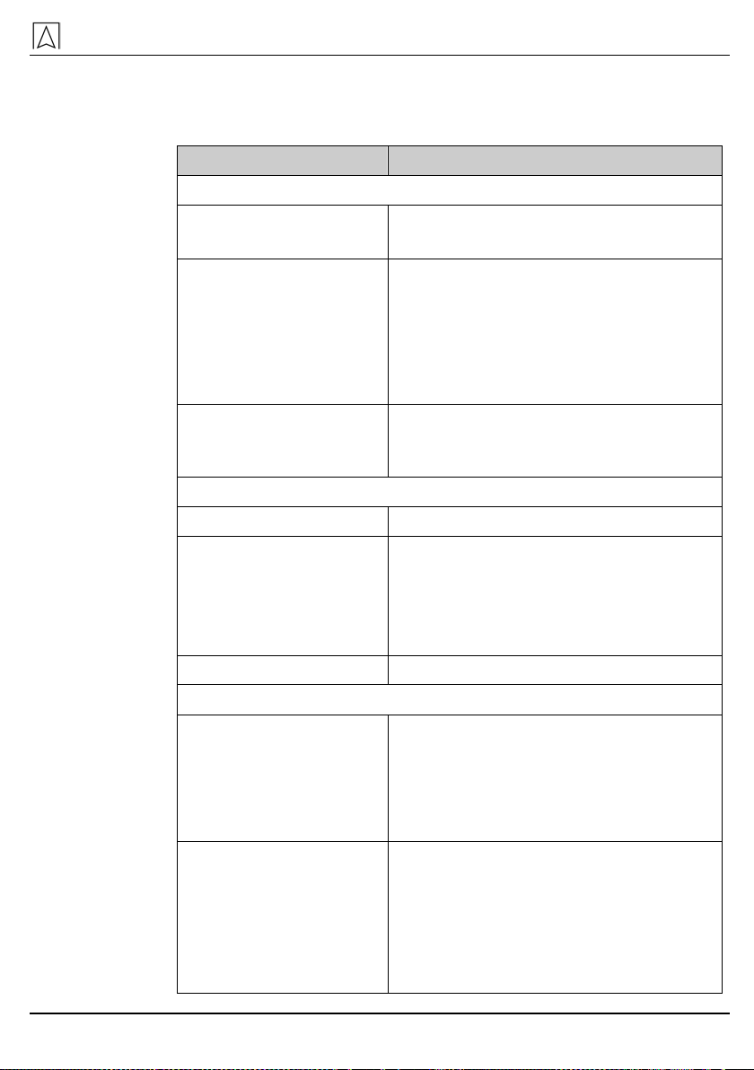
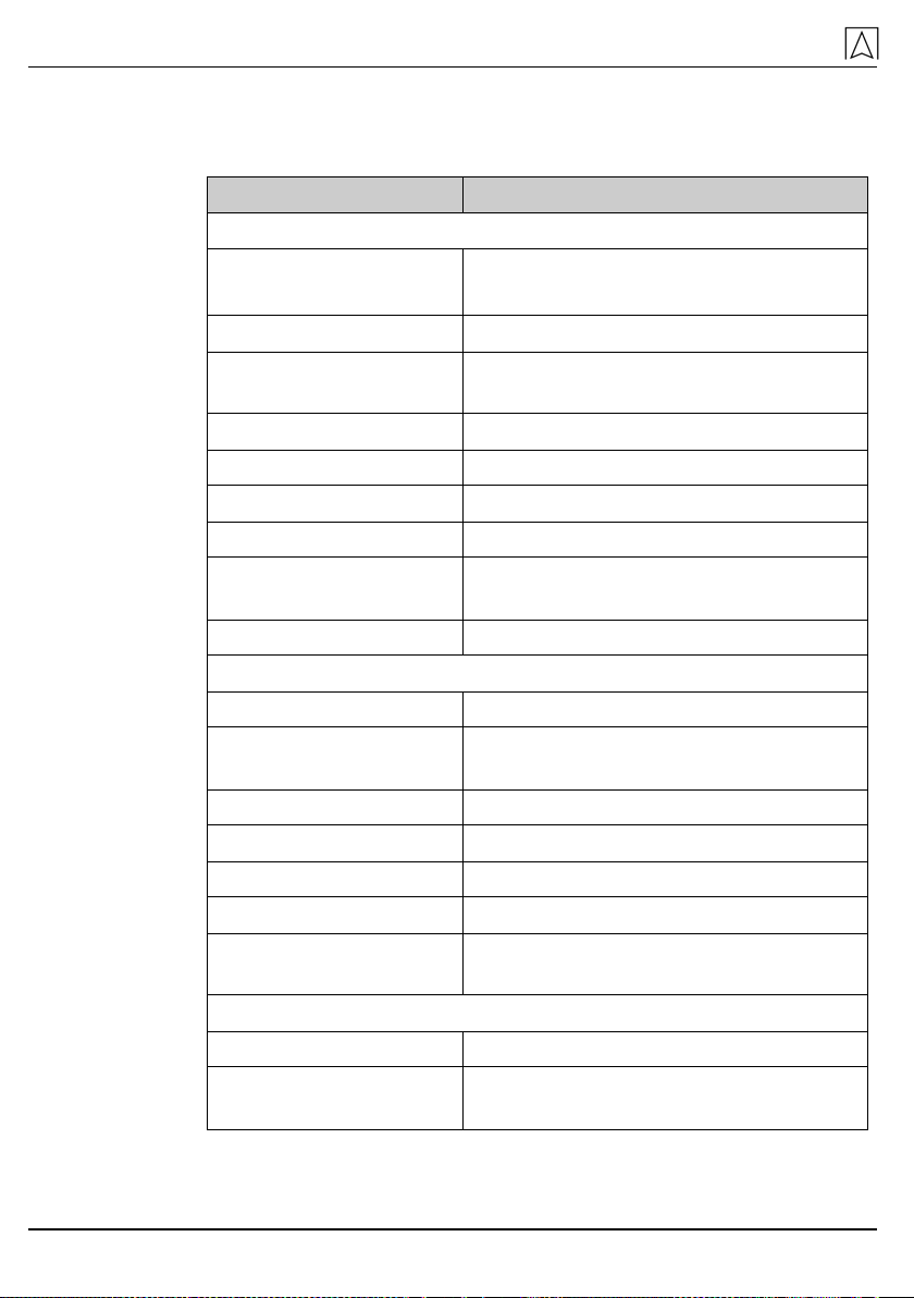
Table 1: Technical specifications Bourdon tube pressure gauges
Parameter Value
General specifications
Measuring ranges -1/0 bar to -1/15 bar
0/0.6 bar to 0/1600 bar
Temperature perfor-
mance Rising temperature approx. +0.4 %/K
Falling temperature approx. -0.5 %/K
(indication error when the temperature
of the measuring system deviates from
the normal temperature of 20 °C, with
reference to the full scale value)
Operating frequency in
hazardous areas (EX
areas).
Max. 0.1 Hz
Operating temperature range
Ambient -20 °C to +60 °C
Fluid Max. +60 °C for liquid filled devices and
devices with soft-soldered Bourdon
tubes
Max. +100 °C for non-filled devices with
hard-soldered or welded bourdon tube
Storage -40 °C to +70 °C
Application area with static load
Up to full scale value
Type: D4, D5, D8
Type: D2, D3
Type: D1
In NS 100, NS 160, NS 250 (cl. 1.0 up
to ≤600 bar)
In NS 100 (cl. 1.0)
In NS 4½"
Up to ¾ full scale value
Type: D1, D6, D7, D9,
D0
Type: D2, D3, D4, D8
Type: D2
Type: D4
All nominal sizes
In NS 40, NS 50, NS 63, NS 80
In NS 100 (cl. 1,6)
In NS 160, NS 250 (cl. 0.6 cl. 0.25
cl. 0.1 and cl. 1.0 > 600 bar)
Technical specifications
16 Bourdon tube, capsule, diaphragm, spring diaphragm pressure gauges
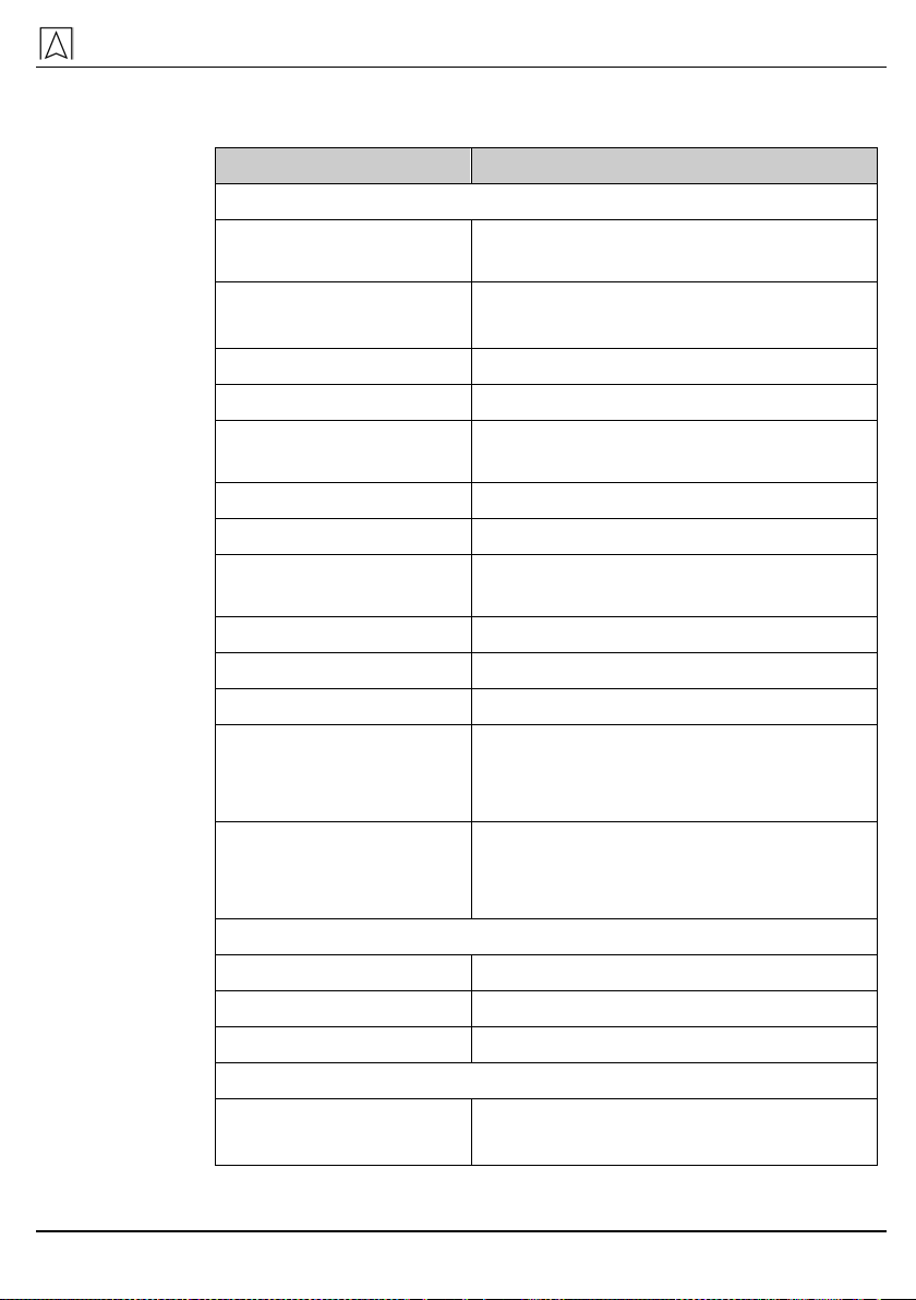
Table 2: Technical specifications Bourdon tube pressure gauge with
clamp type chemical seal
Parameter Value
General specifications
Degree of protection > 25 bar = IP 65 (as per EN 60529)
≤25 bar = IP 54 (as per EN 60529)
Ranges 0.6-40 bar
Permissible operating
pressure Max. ¾ x full scale value
Overpressure safety Full scale value
Connection Clamp as per ISO 2852
Nominal diameter DN 1", DN 1½", DN 2", DN 2½", DN 3"
Surface roughness Ra = 0.8 (wetted surfaces)
Accuracy Cl. 1.6 (as per EN 837-1) at +20 °C;
cl. 1.0 on request
Mounting position Vertical (NL90 ±5° as per DIN 16257)
Materials
All wetted parts 316 L (1.4404/1.4435)
Pressure gauge connec-
tion 1.4571/1.4404
Housing/ crimped bezel 1.4301
Filling plug PUR
Window Safety glass/polycarbonate
Housing seal NBR/PUR
Filling liquid Paraffin oil or silicone oil, (FDA-
compliant)
Operating temperature range
Ambient -20 °C to +60 °C
Fluid +80 °C (when mounted: short-term
+140 °C for sterilisation)
Technical specifications
Bourdon tube, capsule, diaphragm, spring diaphragm pressure gauges 17
Table 3: Technical specifications Bourdon tube pressure gauge
NS 50 with inductive contact
Parameter Value
General specifications
Nominal operating volt-
age Nom. 8.2 V DC
Current input Active area free > 3 mA
Active area covered < 1 mA
Type of output NAMUR
Degree of protection IP 32 (as per EN 60529)
Permissible operating
pressure Max. full scale value
Overpressure safety Short-term 1.15 x
Connection G¼B or ¼-18 NPT (as per EN 837-1)
Width across flats,
spanner SW 14
Accuracy Cl. 1,6 (as per EN 837-1) at +20 °C
Switching accuracy ±2.5 % of full scale value
Mounting position Vertical (NL90 ±5° as per DIN 16257)
Connection cable
RF50 Ex IK1.2
RF50 IK1.2
2 m, LiYY blue 2 x 0.14 mm²
2 m, LiYY grey 2 x 0,25 mm²
Pin assignment
Grey cable
Blue cable
WH (white)/+ BN (brown)
BL (blue)/+ BN (brown)
Materials
All wetted parts 1.4571/1.4404
Housing 1.4301
Window/rear wall Polycarbonate
Operating temperature range
Ambient -20 °C to +60 °C
Attention: Fluid must not freeze.
Technical specifications
18 Bourdon tube, capsule, diaphragm, spring diaphragm pressure gauges
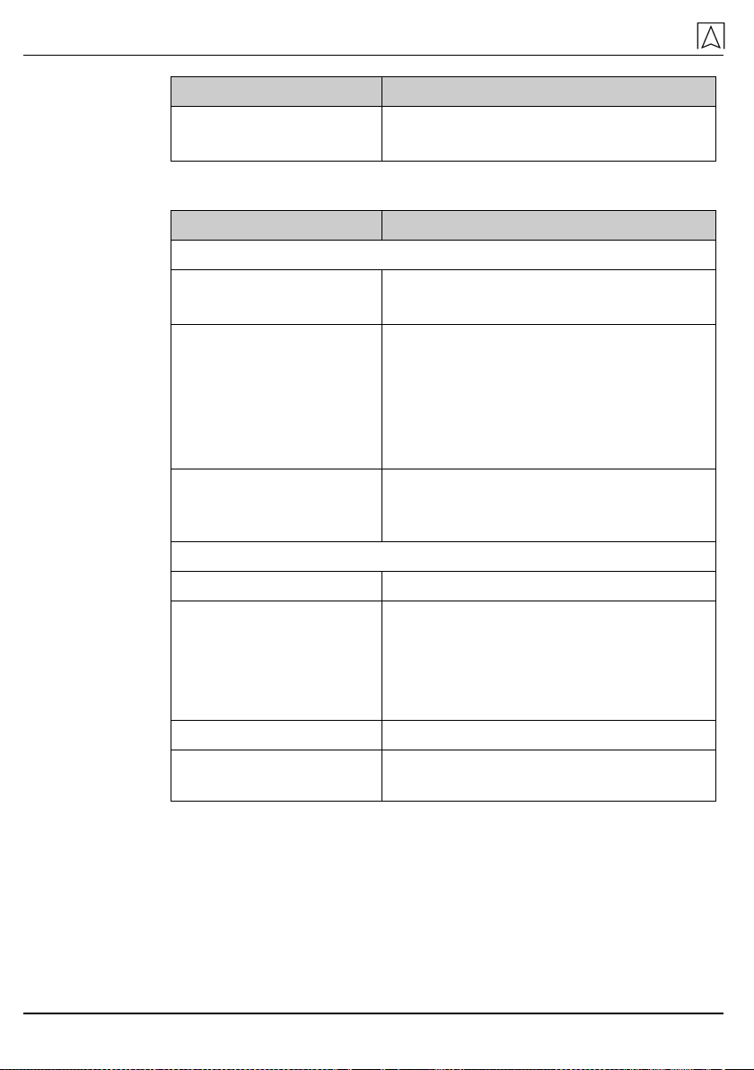
Parameter Value
Fluid Max. +100 °C
Attention: Fluid must not freeze.
Table 4: Technical specifications capsule pressure gauges
Parameter Value
General specifications
Measuring ranges -25/0 mbar to -1000/0 mbar
0/25 mbar to 0/1000 mbar
Temperature perfor-
mance Rising temperature approx. +0.06 %/K
Falling temperature approx. -0.06 %/K
(indication error when the temperature
of the measuring system deviates from
the normal temperature of 20 °C, with
reference to the full scale value)
Operating frequency in
hazardous areas (EX
areas).
Max. 0.1 Hz
Operating temperature range
Ambient -20 °C to +60 °C
Fluid Max. +60 °C for liquid filled devices and
devices with soldered diaphragms made
of copper alloys
Max. +100 °C for non-filled devices with
welded stainless steel diaphragm
Storage -40 °C to +70 °C
Application area with
static load Up to full scale value

Technical specifications
Bourdon tube, capsule, diaphragm, spring diaphragm pressure gauges 19
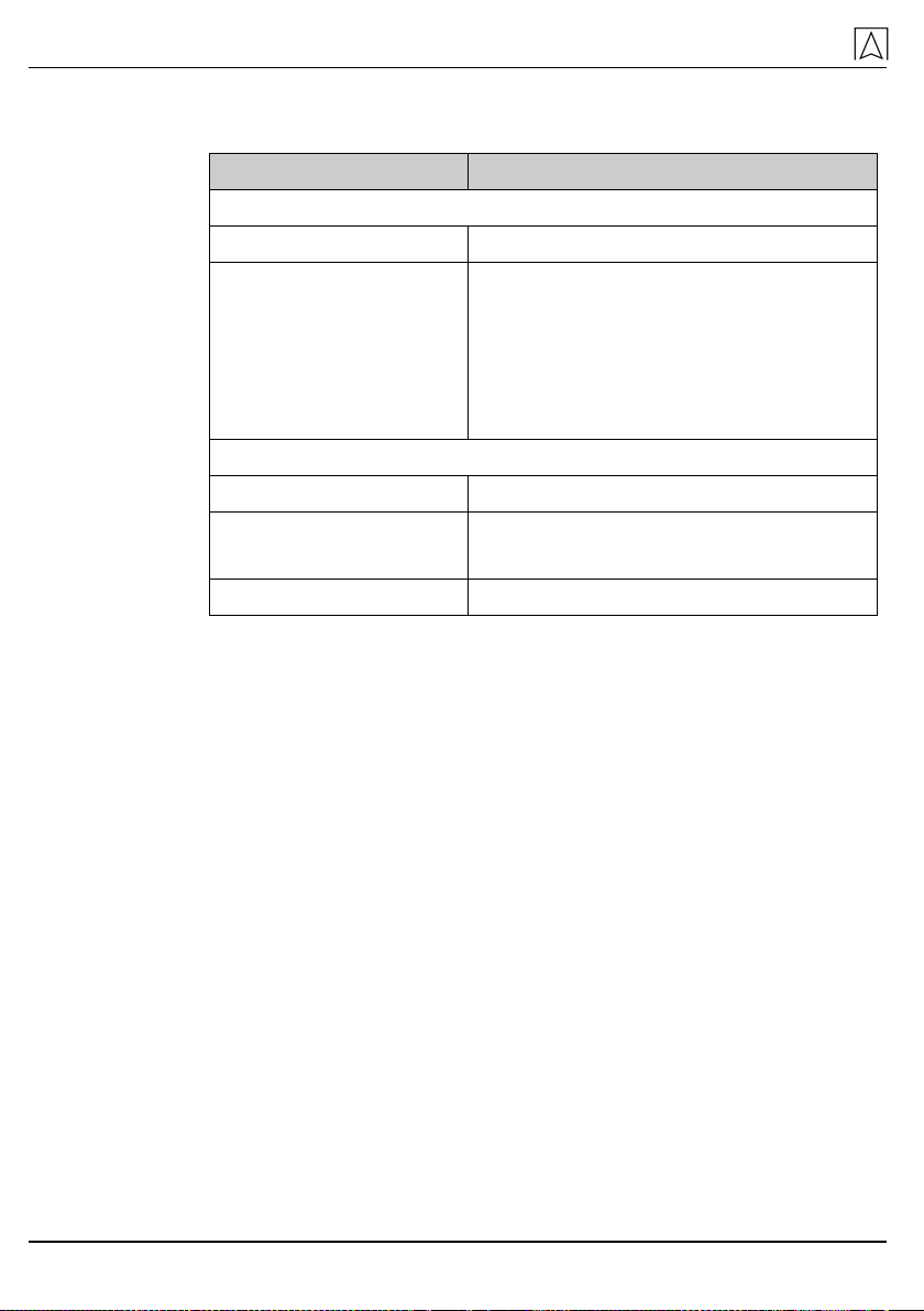
Table 5: Technical specifications diaphragm pressure gauges
Parameter Value
General specifications
Measuring ranges 0/10 mbar to 0/25 mbar
Temperature perfor-
mance Rising temperature approx. +0.08 %/K
Falling temperature approx. -0.08 %/K
(indication error when the temperature
of the measuring system deviates from
the normal temperature of 20 °C, with
reference to the full scale value)
Operating frequency in
hazardous areas (EX
areas).
Max. 0.1 Hz
Operating temperature range
Ambient -20 °C to +60 °C
Fluid Max. +60 °C for liquid filled devices
Max. +100 °C for non-filled devices
Storage -40 °C to +70 °C
Application area with
static load Up to full scale value
Technical specifications
20 Bourdon tube, capsule, diaphragm, spring diaphragm pressure gauges
Table 6: Technical specifications spring diaphragm pressure gauges
(differential pressure)
Parameter Value
General specifications
Measuring ranges 0/250 mbar to 0/6 bar
Temperature perfor-
mance Rising temperature approx. +0.05 %/K
Falling temperature approx. -0.05 %/K
(indication error when the temperature
of the measuring system deviates from
the normal temperature of 20 °C, with
reference to the full scale value)
Operating temperature range
Ambient -20 °C to +60 °C
Fluid Max. +60 °C
Attention: Fluid must not freeze.
Storage -40 °C to +70 °C
See the current AFRISO catalogue or www.afriso.com for additional
technical specifications
5.1 Approvals, tests and conformities
Bourdon tube pressure gauges comply with the European standard
for pressure measuring instruments EN 837-1, capsule pressure
gauges and diaphragm pressure gauge comply with EN 837-3.
Pressure gauges with a full scale value e500 mbar comply with the
Pressure Equipment Directive (2014/68/EU).
Bourdon tube pressure gauges with clamp chemical seal
The pressure gauges also comply with the US standard 3-A Sanitary
Standard 74-03.
Bourdon tube pressure gauge NS50 with inductive contact
The pressure gauges also comply with the ATEX directive
(2014/34/EU).
This manual suits for next models
9
Table of contents
Other Afriso EURO-INDEX Measuring Instrument manuals


