Afriso EURO-INDEX Unimes E User manual
Mess-, Regel- und
Überwachungsgeräte
für Haustechnik,
Industrie und Umweltschutz
Lindenstraße 20
DE-74363 Güglingen
Phone: +49(0)7135-102-0
Service: +49(0)7135-102-211
Telefax: +49(0)7135-102-14
7
E-Mail: info@afriso.de
Internet: www.afriso.de
Read instructions before using device!
Observe all safety information!
Keep instructions for future use!
Version: 10.2007
Id. no.: 854.001.0422
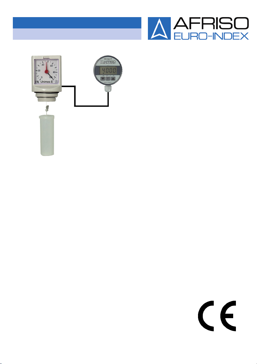
Operating Instructions
Mechanical Tank Contents Gauge with
Electronic Remote Indication
Type: Unimes E
Part no.: 52130

2 Unimes E
Contents
1This instruction manual............................................................................................4
1.1 Precautions...................................................................................................4
1.2 Explanation of symbols and typeface...........................................................4
2Safety.......................................................................................................................5
2.1 Intended use.................................................................................................5
2.2 Predictable incorrect application ..................................................................5
2.3 Safe handling................................................................................................5
2.4 Staff qualification ..........................................................................................6
2.5 Modifications to the product..........................................................................6
2.6 Usage of spare parts and accessories .........................................................6
2.7 Liability information.......................................................................................6
3Product description ..................................................................................................7
3.1 Scope of delivery ..........................................................................................7
3.2 Function........................................................................................................8
3.3 Application example .....................................................................................8
4Technical specifications...........................................................................................9
4.1 Approvals, tests, conformities.....................................................................10
5Transport and storage ...........................................................................................10
6Mounting and commissioning ................................................................................11
6.1 Determining the tank data ..........................................................................11
6.2 Mounting the wall bracket for the remote indicator ....................................12
6.3 Adjusting the float .......................................................................................12
6.4 Adjusting the tank height at the direct indication gauge.............................12
6.5 Connecting the direct indication gauge and the remote indicator ..............13
6.6 Connecting the battery of the remote indicator ..........................................13
6.7 Zero point adjustment at the remote indicator............................................14
6.8 Entering the tank data at the remote indicator ...........................................15
6.9 Mounting the direct indication gauge..........................................................16
7Operation ...............................................................................................................16
7.1 Switching Unimes E on and off ..................................................................16
7.2 Display formats of the remote indicator......................................................17
7.3 Correcting the tank data of the remote indicator ........................................17
7.4 Subsequent zero point adjustment at the remote indicator........................17
8Maintenance ..........................................................................................................18
8.1 Maintenance times .....................................................................................18
8.2 Replacing the battery of the remote indicator.............................................18
9Troubleshooting .....................................................................................................18

Unimes E 3
10 Shutting down, disposal ........................................................................................ 19
11 Spare parts and accessories ................................................................................ 19
12 Warranty................................................................................................................ 20
13 Copyright............................................................................................................... 20
14 Customer satisfaction ........................................................................................... 20
15 Addresses ............................................................................................................. 20

This instruction manual
4 Unimes E
1 This instruction manual
This instruction manual is part of the product.
Read this manual before using the instrument.
Keep this manual during the entire service life of the product
and always have it readily available for reference.
Always hand this manual over to future owners or users of the
product.
1.1 Precautions
WARNING TERM
Type and source of the danger are shown here.
Precautions to take in order to avoid the danger are shown
here.
There are three different levels of warnings:
Warning term Meaning
DANGER Immediately imminent danger!
Failure to observe the information will result in
death or severe injuries.
WARNING Possibly imminent danger!
Failure to observe the information may result in
death or severe injuries.
CAUTION Dangerous situation!
Failure to observe the information may result in
minor or severe injuries as well as damage to
property.
1.2 Explanation of symbols and typeface
Symbol Meaning
Prerequisite for an activity
Activity consisting of a single step
1. Activity consisting of a several steps
Result of an activity
• Bulleted list
Text Indication on display
Highlighting Highlighting

Safety
Unimes E 5
2 Safety
2.1 Intended use
Unimes E is only suitable for continuous level measurement in tanks
containing fuel oil EL, diesel and other low-viscosity media which do
not attack the materials used (refer to chapter 4, page 9). For tank
heights from 900 to 2000 mm.
Any use other than the application explicitly permitted in this instruc-
tion manual is not permitted.
2.2 Predictable incorrect application
Unimes E must never be used in the following cases:
• Hazardous areas (ex)
• Applications involving persons and animals
2.3 Safe handling
Unimes E represents state-of-the-art technology and is made ac-
cording to the pertinent safety regulations. Each device is subjected
to a function and safety test prior to shipping.
Operate Unimes E only when it is in perfect condition. Always
observe the operating instructions, all pertinent local and na-
tional directives and guidelines as well as the applicable safety
regulations and directives concerning the prevention of acci-
dents.
Unimes E is not safety equipment. It does not replace the func-
tion of a level sensor at the fuel oil tank.
Unimes E may only be installed in unpressurised tanks. An ap-
proved tank vent and a fully functional level sensor must be in-
stalled.
The measured values displayed, in particular the values of the
litre indication, must not be used for billing purposes. The accu-
racy of the measured values displayed depends on the accu-
racy of the tank data determined and entered. Therefore, the
accuracy required for billing purposes cannot be guaranteed by
the manufacturer.
Extreme environmental conditions have negative effects on the func-
tion of the product.
Protect the product from shocks.
Only use the product in rooms.
Protect the product from humidity.

Safety
6 Unimes E
2.4 Staff qualification
The product may only be mounted, commissioned, operated, main-
tained, shut down and disposed of by qualified, specially trained
staff.
Electrical work may only be performed by trained electricians quali-
fied in accordance with the local and national directives such as
VDE.
2.5 Modifications to the product
Changes or modifications made to the product by unauthorised per-
sons may lead to malfunctions and are prohibited for safety reasons.
2.6 Usage of spare parts and accessories
Usage of unsuitable spare parts and accessories may cause dam-
age to the product.
Use only genuine AFRISO-EURO-INDEX GmbH spare parts
and accessories (refer to chapter 11, page 19).
2.7 Liability information
AFRISO-EURO-INDEX GmbH shall not be liable in any form
whatsoever for damages and consequential damages resulting from
failure to observe the technical instructions, guidelines and
recommendations.
The manufacturer or the sales company shall not be liable for costs
or damages incurred by the user or by third parties in the usage or
application of this device, in particular in case of improper use of the
device, misuse or malfunction of the connection, malfunction of the
device or of connected devices. The manufacturer or the sales
company shall not be liable for any damage whatsoever resulting
from any use other than the use explicitly permitted in this instruction
manual.
AFRISO-EURO-INDEX GmbH shall not be liable for misprints.
Product description
Unimes E 7
3 Product description
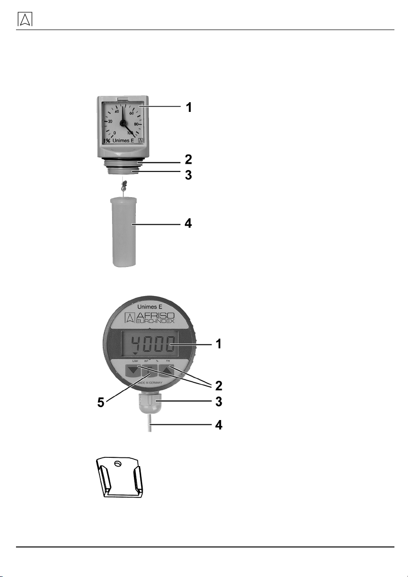
3.1 Scope of delivery
• Direct indication gauge with float
1 Direct indication gauge
2 G2 thread
3 G1½ thread
4 Float
• Remote indicator with battery and connection cable
1 Display
2 Programming keys
3 PG cable gland
4 Connection cable
5 Function key
• Wall bracket for remote indicator

Product description
8 Unimes E
3.2 Function
The direct indication gauge is a universal mechanical tank contents
gauge. It features a fully adjustable brass and nickel silver gear train
mechanism. The pointer movement is always 270° when the tank is
full. The level is indicated in percentage of height. An electronic sen-
sor is located at the movement. It supplies the remote indicator with
a signal that is proportional to the level.
The remote indicator is connected to the mechanical gauge by
means of a 3-core screened cable and plug. The remote indicator is
operated by means of a long-lasting battery. It is only switched on to
read the level (push-to-read function). Diverse tank shapes are
stored in a microprocessor so that the level is indicated either in liq-
uid level or volume, as desired.
This combination of devices allows you to check the supply directly
next to the tank and from an easily accessible, different location.
The measurement signal is transmitted to the remote indicator via
the cable. Using this signal, the electronic system of the remote indi-
cator calculates the tank contents which can be displayed in litres,
cubic metres, percentage or liquid level. The display mode is se-
lected by means of function key F. The two programming keys
and are used to enter the tank data.
3.3 Application example
Fig. 1: Application example
Technical specifications
Unimes E 9
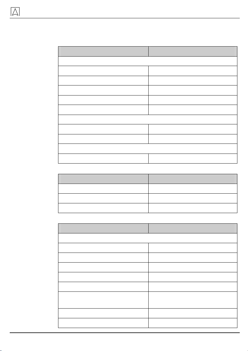
4 Technical specifications
Table 1: Direct indication gauge
Parameter Value
General specifications
Housing dimensions (ø x H) 80 x 100 mm
Weight 180 g
Housing material Impact-resistant ABS
Display Percentage (%)
Mounting Double thread G2-G1½
Operating temperature range
Medium 0 °C to +60 °C
Storage -5 °C to +80 °C
Electrical safety
Protection IP 30 EN 60529
Table 2: Float
Parameter Value
Housing dimensions (ø x H) 42 x 100 mm
Weight 95 g
Housing material PE-HD
Table 3: Remote indicator
Parameter Value
General specifications
Dimensions (ø x D) 75 x 50 mm
Weight 380 g
Cable length 10 m
Housing material PA6 15 % glass loaded
Supply 3.6 V lithium battery
Service life of battery Max. 8 years (if F key is
pressed once per month)
Display 4-digit LC display
Resolution 14 bits

Transport and storage
10 Unimes E
Parameter Value
Measurement input 0 to 3.6 V
Accuracy* < ± 1.0 % FSO, IEC 60770
Operating temperature range
Ambient 0 °C to +45 °C
Storage -5 °C to +80 °C
Electrical safety
Protection IP 51 EN 60529
Electromagnetic compatibility (EMC)
Interference According to EN 50081-1
Noise immunity According to EN 50082-1
Accuracy of the complete system*: < ± 5 % FSO, IEC 60770
* relating to indication of the liquid level in mm.
4.1 Approvals, tests, conformities
Unimes E complies with the EMC directive (89/336/EEC und
92/31/EEC).
5 Transport and storage
CAUTION
Damage to the device due to improper transport.
Do not throw or drop the device.
CAUTION
Damage to the device due to improper storage.
Protect the device from shock when storing it.
Store the device in a clean and dry environment.
Only store the device within the permissible temperature
range.

Mounting and commissioning
Unimes E 11
6 Mounting and commissioning
6.1 Determining the tank data
Before Unimes E can be installed, you must determine the tank data.
For safety reasons and to facilitate subsequent checks, you should
document the tank data on this page.
Tank shape
Determine the tank shape code using the table below.
Example for linear indication: tank shape code 1.
Tank shape
code
Tank shape Description
1 Linear tank Rectangular tanks, upright cylin-
ders, steel tanks welded in the
basement and all other linear
measuring applications
2 Cylindrical tank Vertically mounted cylinders
3 Ball-shaped tank Tanks with the shape of a ball
4 Plastic battery
type tank
Plastic battery type tanks with
straps or bulges
5 Oval tank Oval basement tanks, e.g. glass-
fibre re-enforced tanks or sheet
metal tanks
6 Plastic tank with
recess
Plastic tanks with larger recesses
in the tank centre (manufacturers:
e.g. Roth, Werit)
Determined tank shape code:
Tank volume
Determine the total volume of the tank facility.
Determined tank volume: litres
Tank height (max. liquid level)
Determine tank height.
Determined tank height: mm
Current liquid level
Determine the current liquid level as accurately as possible.
Determined liquid level: mm

Mounting and commissioning
12 Unimes E
6.2 Mounting the wall bracket for the remote indicator
Mount the wall bracket to the wall where you want to position
the remote indicator using the enclosed screw (4 x 30 mm) and
a dowel, if required (6 mm).
6.3 Adjusting the float
A free connection G1½ or G2 is available at the tank.
The float wire has three lead seals. Lead seal 1 is located at the end,
lead seal 2 is located 15 cm higher. The moving lead seal 3 is lo-
cated between these two lead seals.
1 Lead seal 1: fixated
2 Lead seal 2: fixated
3 Lead seal 3: moving
Fig. 2: Float wire
Tank without manhole or flange connection piece
Push the float up to lead seal 2 and press lead seal 3 together
to fixate the float.
Tank with manhole or flange connection piece
1. Deduct the excess length of the manhole or the flange connec-
tion piece with reference top the wire length from probe 2 to-
wards probe 1.
2. Mark the point, push the float up to the mark and press lead
seal 3 together to fixate the float
6.4 Adjusting the tank height at the direct indication gauge
The direct indication gauge is factory-adjusted to the maximum
height which corresponds to a tank height or diameter or 200 cm.

Mounting and commissioning
Unimes E 13
1. Adjust the length of the float wire to the tank height according to
the illustration below:
1 Height of flange
connection piece
2 Fixed lead seal
3 Ø or height
2. Hold the float wire in this position.
3. Turn the adjustment screw to set the pointer to zero.
The direct indication gauge is now adjusted to the tank.
6.5 Connecting the direct indication gauge and the remote indi-
cator
Plug the connector of the connection cable into the rear side of
the direct indication gauge.
6.6 Connecting the battery of the remote indicator
1. When the direct indication gauge and the remote indicator are
electrically connected, open the housing of the remote indicator
by turning the upper part all the way to the stop and pulling it
open.

Mounting and commissioning
14 Unimes E
2. Press mini button (1) and hold it down. Plug the two-pole battery
plug into the two-pole socket (2) on the PCB.
1 Mini button
2 Socket
Fig. 3: PCB
WARNING
Danger of explosion due to short circuit of lithium battery
Do not short-circuit the lithium battery.
3. Release the mini button.
6.7 Zero point adjustment at the remote indicator
The pointer of the direct indication gauge points to zero.
1. Close the housing of the remote indicator by pushing the hous-
ing parts together.
The remote indicator was switched on when the battery was con-
nected. The display toggles between "Zero" and the current offset of
the complete system. The upper left corner of the display shows the
two arrows to indicate that the instrument is in calibration mode.
2. Press the two keys and simultaneously in order to correct
the offset to the value 0.00.
In this state, zero calibration can be performed any number of
times.
3. Press the F key in order to terminate zero calibration.
An arrow pointing to the unit "Litres" is displayed at the bottom
of the display.

Mounting and commissioning
Unimes E 15
6.8 Entering the tank data at the remote indicator
Zero calibration has been performed.
The pointer of the direct indication gauge points to 100 %.
Tank shape
The arrow at the bottom of the display points to the unit "Litres".
The display shows the code of the selected tank shape. When
the unit is commissioned for the first time, the displayed code is
0. Code 0 means that no tank shape has yet been selected.
1. Use the keys and to set the code of the tank shape deter-
mined. Refer to chapter 6.1, page 11.
2. Press the F key to accept the setting and continue with the tank
volume.
Tank volume
The arrow at the bottom of the display points to the unit m³.
The display shows the currently selected tank volume. 0000
means that no tank volume has yet been entered.
1. Use the and keys to enter the total volume of the tank fa-
cility. By pressing the key, you can select the digit to be
changed. The key allows you to change the selected digit
within a range from 0 to 9.
2. Up to a volume of 9999 litres, the volume is entered in litres
without decimal places. In the case of volumes of > 9999 litres,
the value is entered in cubic metres with a decimal place (1000
litres = 1 cubic metre). The decimal place is moved with the
key.
3. Press the F key to accept the setting and continue with the tank
height.
Tank height
The arrow at the bottom of the display points to the unit "Per-
cent". The display shows the currently selected tank height.
0000 means that no tank height has yet been entered.
1. Set the tank height in mm with the keys: By pressing the
key, you can select the digit to be changed. The key allows
you to change the selected digit within a range from 0 to 9.
2. Press the F key to accept the setting and continue with the cur-
rent level.

Operation
16 Unimes E
Maximum liquid level
The pointer of the direct indication gauge points to 100 %.
The arrow at the bottom of the display points to the unit "Level"
(FH). The display shows the maximum liquid level in mm meas-
ured by the direct indication gauge.
1. Overwrite the displayed value to correct the displayed maximum
liquid level: Set the liquid level in mm with the and keys.
By pressing the key, you can select the digit to be changed.
The key allows you to change the selected digit within a
range from 0 to 9.
2. Press the F key to accept the setting.
You have now entered all the tank data and the remote indicator
switches to normal measurement mode.
The symbol in the upper left corner of the display is no
longer shown.
6.9 Mounting the direct indication gauge
1. Slowly lower the float into the tank.
2. Screw the direct indication gauge into the tank.
7 Operation
7.1 Switching Unimes E on and off
Direct indication gauge
The direct indication gauge is always on.
Remote indicator
Press the F key to switch on the display of the remote indicator.
The remote indicator automatically switches off approx. 2 ½
minutes after the last time a key was pressed.
The display shows OFF.
In this mode, the battery is not discharged. By pressing the F key,
you switch on the remote indicator for another 2 ½ minutes, i.e. the
level is indicated.

Operation
Unimes E 17
7.2 Display formats of the remote indicator
Direct indication gauge
The liquid level is displayed in %.
Remote indicator
Keep pressing the F key to select one of the four available units
for the level:
• Indication of volume in litres.
The arrow at the bottom of the display points to "Litres".
• Indication of volume in m³.
The arrow at the bottom of the display points to m³.
• Indication of volume in % of total contents.
The arrow at the bottom of the display points to %.
• Indication of liquid level in mm.
The arrow at the bottom of the display points to FH.
7.3 Correcting the tank data of the remote indicator
If the measured value exceeds the set tank data (e.g. due to incor-
rect tank data), the display starts to flash. The display toggles be-
tween the displayed value and "----". Only the current liquid level in
mm is displayed permanently.
1. Hold down the keys simultaneously for 3 seconds to acti-
vate the "Enter Tank Data" mode.
The upper left corner of the display shows the symbol .
2. The individual tank data can be checked and/or overwritten as
described in chapter 6.1, page 11.
If you do not want to change tank data, press the F key four
times to return to the normal measurement mode.
The upper left corner of the display no longer shows the symbol
.
7.4 Subsequent zero point adjustment at the remote indicator
The pointer of the direct indication gauge points to zero.
1. Unplug the battery connector from the PCB.
2. Proceed as described in chapter 6.6, page 13, to chapter 6.8,
page 15.
If you press the mini button when connecting the battery con-
nector, all tank data is cleared.

Maintenance
18 Unimes E
8 Maintenance
8.1 Maintenance times
When Activity
is shown on the display of
the remote indicator.
Replace the battery as de-
scribed in chapter 8.2, page
18.
8.2 Replacing the battery of the remote indicator
1. Remove the old battery and connect the new battery (refer to
chapter 6.6, page 13).
2. To protect the environment, used batteries must not be dis-
posed of together with the normal household waste. Return
empty batteries to the point of purchase or to special collecting
points.
Saved tank data is not lost when the battery is replaced.
9 Troubleshooting
Repairs may only be performed by specially trained, qualified staff.
Table 4: Troubleshooting
Problem Possible reason Repair
"OFF" is shown on
the display of the
remote indicator.
Automatic shut-
down after 2 ½
minutes.
Press F key to
read the liquid
level.
is shown on the
display of the re-
mote indicator.
Battery voltage
below critical
value.
Replace battery
(refer to chapter
8.2, page 18).
The battery is not
connected.
Connect the bat-
tery (refer to chap-
ter 6.6, page 13).
Display of the re-
mote indicator is
blank.
The battery con-
nector is not con-
nected to the
printed.
Check the battery
connector.
The display toggles
between the dis-
played value and "---
-".
Incorrect tank data
entered.
Correct the tank
data (refer to chap-
ter 7.3, page 17).

Shutting down, disposal
Unimes E 19
Problem Possible reason Repair
Incorrect indication
of level at remote
indicator.
Incorrect tank data
entered.
Correct the tank
data (refer to chap-
ter7.3, page 17).
The display toggles
between the "9999"
and "----".
Cable break or
remote indicator
not connected to
direct indication
gauge.
Check cable and
connection.
Display of the re-
mote indicator
shows "0" in spite of
contents > 0.
Short circuit in the
connection cable
between direct
indication gauge
and remote con-
nector.
Check cable.
Other malfunctions – Send the device to
AFRSIO.
10 Shutting down, disposal
1. Dismount the device (see chapter 6, page 11, reverse sequence
of steps).
2. To protect the environment, this device must not be disposed
of together with the normal household waste. Dispose of the de-
vice according to the local conditions and directives.
This device consists of materials that can be reused by recycling
firms. The electronic inserts can be easily separated and the device
consists of recyclable materials.
If you do not have the opportunity to dispose of the used device in
accordance with environmental regulations, please contact us for
possibilities to return it.
11 Spare parts and accessories
Part Part no.
Direct indication gauge with float 06 15 07
Remote indicator 06 15 000010
3.6 V lithium battery 68309
Bracket for wall mounting 00 24 000111

Warranty
20 Unimes E
12 Warranty
The warranty of AFRISO-EURO-INDEX GmbH for this product is 24
months after the date of purchase. This warranty shall be good in all
countries in which this device is sold by AFRISO-EURO-INDEX
GmbH or its authorised dealers.
13 Copyright
AFRISO-EURO-INDEX GmbH retains the copyright to this manual.
This manual may only be reprinted, translated, copied in part or in
whole with the prior written consent of AFRISO-EURO-INDEX
GmbH.
We reserve the right to technical modifications with reference to the
specifications and illustrations in this manual.
14 Customer satisfaction
Customer satisfaction is the prime objective of AFRISO-EURO-
INDEX GmbH.. Please get in touch with us if you have any ques-
tions, suggestions or problems concerning your AFRISO product.
15 Addresses
The addresses of our worldwide representations and offices can be
found on the Internet at www.afriso.de.
Table of contents
Other Afriso EURO-INDEX Measuring Instrument manuals


