Afriso EURO-INDEX TankControl 01 User manual

Mess-, Regel- und
Überwachungsgeräte
für Haustechnik,
Industrie und Umweltschutz
Lindenstraße 20
DE-74363 Güglingen
Telefon: +49(0)7135-102-0
Service: +49(0)7135-102-211
Telefax: +49(0)7135-102-14
7
E-Mail: info@afriso.de
Internet: www.afriso.de
Read instructions before using device!
Observe all safety information!
Keep instructions for future use!
Version: 04.2008
ID no.: 854.001.0444
Operating Instructions
Hydrostatic Level Indicator
for Fuel Oil and Diesel
Type: TankControl
TankControl 01 Part no.: 52132

2 TankControl 01
Contents
1 This instruction manual ............................................................................................4
1.1 Precautions...................................................................................................4
1.2 Explanation of symbols and typeface...........................................................4
2 Safety.......................................................................................................................5
2.1 Intended use .................................................................................................5
2.2 Predictable incorrect application ..................................................................5
2.3 Safe handling................................................................................................5
2.4 Staff qualification ..........................................................................................5
2.5 Modifications to the product..........................................................................6
2.6 Usage of spare parts and accessories .........................................................6
2.7 Liability information.......................................................................................6
3 Product description ..................................................................................................6
3.1 Scope of delivery ..........................................................................................6
3.2 Properties .....................................................................................................7
3.3 Application example .....................................................................................7
3.4 Key functions ................................................................................................8
3.5 Overview of the signals ................................................................................8
3.6 Overview of the screen structure..................................................................9
3.7 Overview of the menu structure .................................................................10
4 Technical specifications.........................................................................................11
4.1 Approvals, tests, conformities.....................................................................12
5 Transport and storage ...........................................................................................13
6 Installation..............................................................................................................13
6.1 Electrical connection...................................................................................16
6.2 Zero calibration of the submersible probe ..................................................17
6.3 Installing the submersible probe.................................................................17
6.4 Mounting the submersible probe to the tank ..............................................18
7 Commissioning ......................................................................................................20
7.1 Password ....................................................................................................20
7.2 Setting the date and the time......................................................................21
7.3 Setting the tank data...................................................................................22
7.4 Setting the alarms.......................................................................................24
8 Operation ...............................................................................................................26
8.1 Changing the display language ..................................................................26
8.2 Alarm condition...........................................................................................27
8.3 Statistics function........................................................................................27
9 Troubleshooting .....................................................................................................29

TankControl 01 3
10 Shutting down, disposal ........................................................................................ 29
11 Spare parts and accessories ................................................................................ 30
12 Warranty................................................................................................................ 30
13 Copyright............................................................................................................... 30
14 Customer satisfaction ........................................................................................... 30
15 Addresses ............................................................................................................. 30

This instruction manual
4 TankControl 01
1 This instruction manual
This instruction manual is part of the product.
X Read this manual before using the product.
X Keep this manual during the entire service life of the product
and always have it readily available for reference.
X Always hand this manual over to future owners or users of the
product.
1.1 Precautions
WARNING TERM
Type and source of the danger is shown here.
X Precautions to take in order to avoid the danger are shown
here.
There are three different levels of warnings:
Warning term Meaning
DANGER Immediately imminent danger!
Failure to observe the information will result in
death or serious injuries.
WARNING Possibly imminent danger!
Failure to observe the information may result in
death or serious injuries.
CAUTION Dangerous situation!
Failure to observe the information may result in
minor or serious injuries as well as damage to
property.
1.2 Explanation of symbols and typeface
Symbol Meaning
; Prerequisite for an activity
Activity consisting of a single step
1. Activity consisting of several steps
ª Result of an activity
• Bulleted list
Text Indication on a display
Highlighting Highlighting

Safety
TankControl 01 5
2 Safety
2.1 Intended use
TankControl 01 may only be used for level measurement of the fol-
lowing liquids:
• Fuel oil EL according to DIN 51603-1
• Fuel oil L according DIN 51603-2
• Diesel according to EN 590
Any use other than the application explicitly permitted in this instruc-
tion manual is not permitted.
2.2 Predictable incorrect application
TankControl 01 must never be used in the following cases:
• Hazardous area (Ex)
If the device is operated in hazardous areas, sparks may cause
deflagrations, fires or explosions.
• Use as safety equipment
TankControl 01 does not replace the function of a level sensor
at the fuel oil tank.
• Use as an overfill alarm system
2.3 Safe handling
TankControl 01 represents state-of-the-art technology and is made
according to the pertinent safety regulations. Each device is sub-
jected to a function and safety test prior to shipping.
X Operate TankControl 01 only when it is in perfect condition. Al-
ways observe the operating instructions, all pertinent local and
national directives and guidelines as well as the applicable
safety regulations and directives concerning the prevention of
accidents.
Extreme environmental conditions have negative effects on the func-
tion of the product.
X Protect TankControl 01 from shocks.
X Only use the control unit indoors.
X Protect the control unit from humidity.
2.4 Staff qualification
The product may only be mounted, commissioned, operated, main-
tained, shut down and disposed of by qualified, specially trained
staff.
Product description
6 TankControl 01
Electrical work may only be performed by trained electricians quali-
fied in accordance with the local and national directives.
2.5 Modifications to the product
Changes or modifications made to the product by unauthorised per-
sons may lead to malfunctions and are prohibited for safety reasons.
2.6 Usage of spare parts and accessories
Usage of unsuitable spare parts and accessories may cause dam-
age to the product.
X Use only genuine spare parts and accessories of the manufac-
turer (refer to chapter 11, page 30).
2.7 Liability information
The manufacturer shall not be liable for direct or consequential dam-
age resulting from failure to observe the technical instructions, guide-
lines and recommendations.
The manufacturer and the sales company shall not be liable for costs
or damages incurred by the user or by third parties in the usage or
application of this device, in particular in case of improper use of the
device, misuse or malfunction of the connection, malfunction of the
device or of connected devices. The manufacturer or the sales com-
pany shall not be liable for damages resulting from any use other
than the use explicitly permitted in this instruction manual.
The manufacturer shall not be liable for misprints.
3 Product description
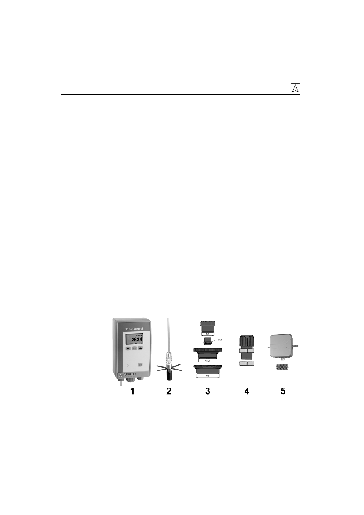
3.1 Scope of delivery
Fig. 1: Scope of delivery TankControl 01
Product description
TankControl 01 7
1Control unit with probe cable
2Submersible probe for fuel oil/diesel with probe cable
3Screw connector kit G1 x G1½ x G2
4Mounting kit for withdrawal flange at plastic battery tanks
5Moisture-proof junction box with terminal strips and fastening
material
Bag of accessories (not shown) with 2 screws and 2 dowels for
wall mounting
3.2 Properties
The hydrostatic level measurement system consists of a control unit
with digital display and a submersible probe with integrated pressure
measuring cell. The system displays the level in litres, cubic metres,
percent or liquid level in millimetres. When the level falls below or
exceeds an adjustable minimum or maximum value, the control unit
triggers visual and, if desired, audible (can be muted) alarms. Two
additional relay contacts are available for external alarm devices, for
level control or for connection to telecommunication or building con-
trol systems. An integrated microprocessor records, stores and dis-
plays important information such as fuel consumption or calculation
of reach (based on past consumption values).
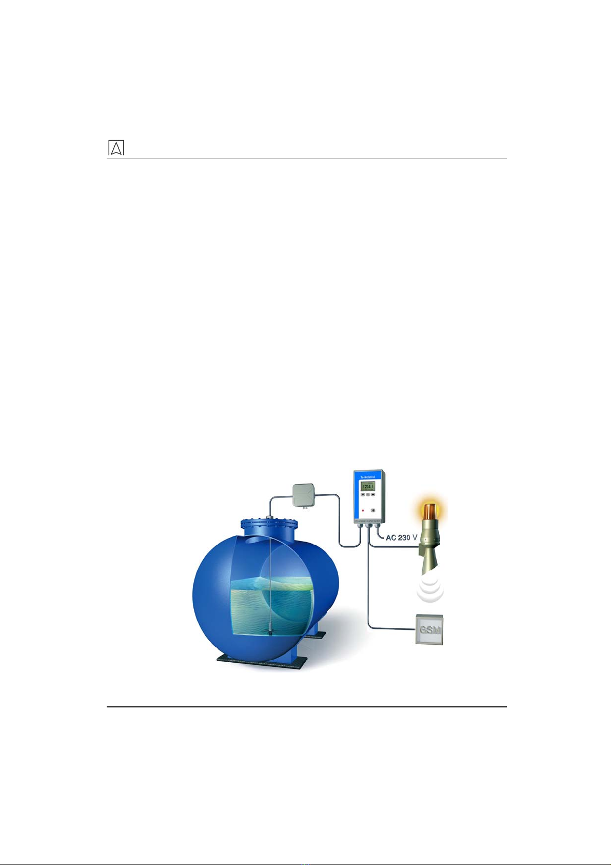
3.3 Application example
Fig. 2: Application example TankControl
Product description
8 TankControl 01
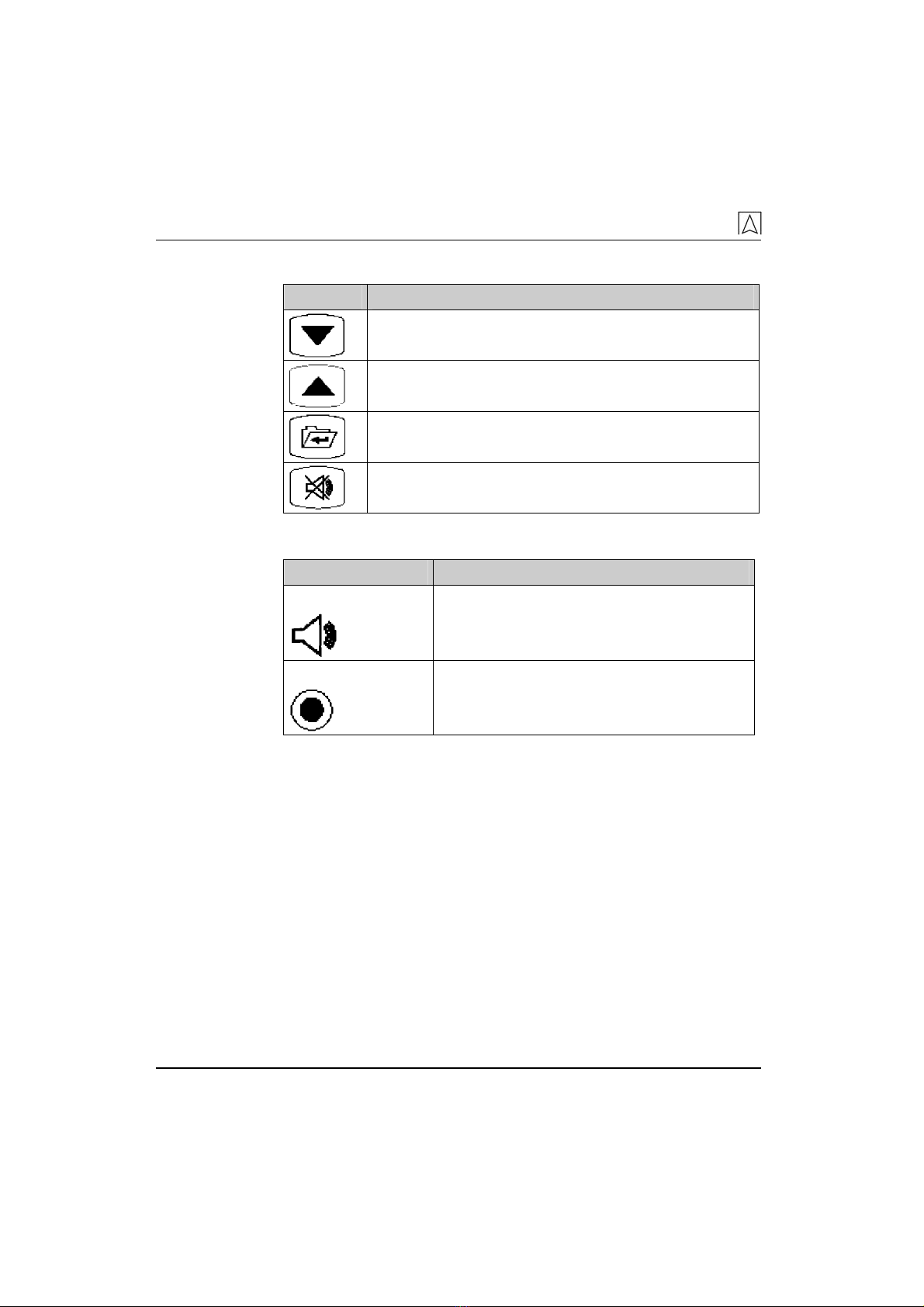
3.4 Key functions
Keys Function
Scroll down/left.
Scroll up/right.
Display main menu.
Make selection and confirm, select.
Mute key: Switch off buzzer during an alarm condition
and display the alarm acknowledgement menu.
3.5 Overview of the signals
Alarm signal Setting
Audible alarm Buzzer sounds during an alarm condition,
depending on the settings.
Visual alarm Red LED always lights up during an alarm
condition.
Product description
TankControl 01 9
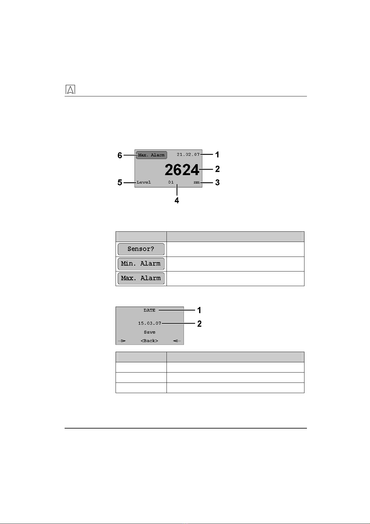
3.6 Overview of the screen structure
The screen backlighting is automatically switched off 5 minutes after
the last time a key was pressed. Pressing any key automatically
switches the screen backlighting on.
Display
1Date
2Current measured
value
3Unit of measurement
4Probe number
5Measured parameter
6Alarm message
Fig. 3: Display
Alarm message Meaning
Sensor failure
Minimum alarm
Maximum alarm
Menu
1Menu title
2Menu item
Display Meaning
Save Save the changed value
<Return> Back to previous menu without saving
ÆÅ
Highlights the currently selected menu item

Product description
10 TankControl 01
3.7 Overview of the menu structure

Technical specifications
TankControl 01 11
4 Technical specifications
Table 1: Technical specifications control unit
Parameter Value
General specifications
Dimensions housing
(W x H x D)
100 x 188 x 65 mm
Length of probe cables 15 m
Housing material Plastic ABS
Operating temperature range
Ambient 0 °C to +45 °C
Storage -5 °C to +80 °C
Voltage supply
Nominal voltage AC 230 V ± 10 %
Rated power 5 VA
Electrical safety
Protection class II EN 60730
Protection IP 54 EN 60529
Electromagnetic compatibility (EMC)
Interference According to EN 61000-6-4
Noise immunity According to EN 61000-6-2
Table 2: Technical Specifications submersible probe for fuel
oil/diesel
Parameter Value
General specifications
Dimensions (Ø x L) 24 x 53 mm
Weight 360 g
Length of probe cable 5 m
Pressure range 0-300 mbar
Accuracy* ≤± 1.0 % FSO, IEC 60770
Temperature error ≤± 1.5 % FSO, 0 to +40 °C
Technical specifications
12 TankControl 01
Parameter Value
Material
Housing Stainless steel 1.4305
Cable PVC fuel oil-resistant
Spacer POM, PE
Other wetted parts Ceramics, silicon, silicon glue, Viton
Operating temperature range
Medium -25 °C to +70 °C
Storage -25 °C to +70 °C
Electrical safety
Protection IP 68 EN 60529
Electromagnetic compatibility (EMC)
Interference According to EN 61000-6-4
Noise immunity According to EN 61000-6-2
* Accuracy of the complete system relating to indication of the liquid
level in mm: < ±1.5 % FSO, IEC 60770
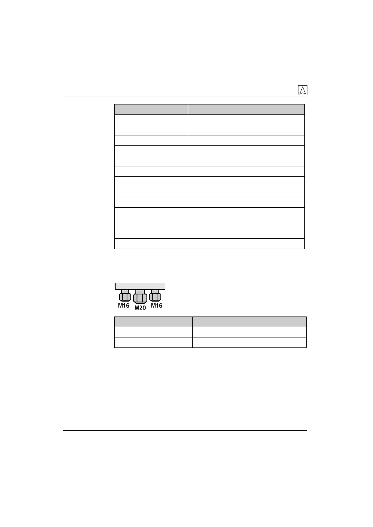
Screw connections at the control unit
Cable gland Cable diameter
M16 4.0-8.8 mm
M20 8.0-12.5 mm
4.1 Approvals, tests, conformities
TankControl complies with the EMC Directive (89/336/EEU and
92/31/EEU) and the Low Voltage Directive (73/23/EEU and
93/68/EEU).
Transport and storage
TankControl 01 13
5 Transport and storage
CAUTION Damage to the device due to improper transport.
X Do not throw or drop the device.
CAUTION Damage to the device due to improper storage.
X Protect the device from shock when storing it.
X Store the device in a clean and dry environment.
X Only store the device within the permissible temperature
range.
6 Installation
;
The installation site of the control unit is accessible and visible
at all times.
;
The installation site of the control unit is at eye level on a plane,
rigid and dry wall.
The provided moisture-proof junction box is not suitable for exterior
application.
X For exterior application use the exterior junction box, refer to
chapter 11, page 30.

Installation
14 TankControl 01
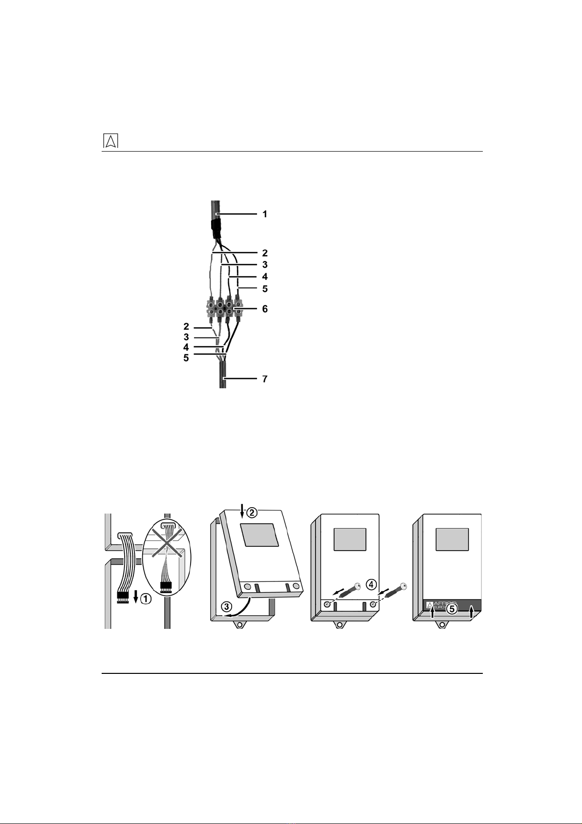
1. Open the control unit.
2. Mount the control unit to the wall.
B 1 Mount the screw to the wall.
2Hang the bottom part to the screw.
ADrill the fastening holes in the bot-
tom part with a Ø 5 mm drill.
Mount the bottom part to the wall
with the screws shipped with the
unit.
3Fixate the bottom part by screwing the
lug to the wall.
3. Mount the junction box at the required location to connect the
cable of the submersible probe and the control unit.
4. Route the cable of the control unit into the junction box.
5. Push the screw connector (screw connector kit or mounting kit,
refer to chapter 6.4, page 18) onto the cable of the submersible
probe; ensure proper orientation.
Installation
TankControl 01 15
6. Route the cable of the submersible probe to the junction box
and connect the two cables using the enclosed terminal strip.
Only connect identical wire colours.
1Control unit
2White (U+)
3Green (signal)
4Brown (U-)
5Yellow-black/yellow-green (shield)
6Terminal strip
7Submersible probe
Fig. 4: Cable connection control unit and submersible probe
7. A transparent hose sticks out from the cable end of the sub-
mersible probe. This hose supplies the pressure sensor with
atmospheric pressure; it must not be closed or bent.
Do not completely close the junction box in order to prevent in-
correct measurements.
8. Connect the unit electrically as described in chapter 6.1 on
page 16.
9. Connect the control unit.

Installation
16 TankControl 01
6.1 Electrical connection
The probe cable for the submersible probe is factory-connected.
;
Mains voltage is interrupted and cannot be switched on by acci-
dent.
Fig. 5: Wiring diagram
Connecting a relay
1. Route the relay cable through the centre screw connection.
2. Connect the relay cable to "Relay A" or "Relay B":
If no error condition is present, the relay is de-energised. In the
case of an alarm, the relay is energised.
NO Relay – Normally Open Not connected to connection A or B
NC Relay – Normally Closed Connected to connection A or B
Connecting the unit to mains
1. Route the mains cable trough the right screw connection.
2. The phase must be connected to terminal L1, the neutral con-
ductor to terminal N and the protective conductor to terminal .

Installation
TankControl 01 17
6.2 Zero calibration of the submersible probe
;
The submersible probe is in air.
;
Submersible probe and control unit are connected.
;
Mains voltage is connected and on.
X Set the current level to „000000 mm“, refer to fig. 11, page 23.
ª
The zero point of the submersible probe was set.
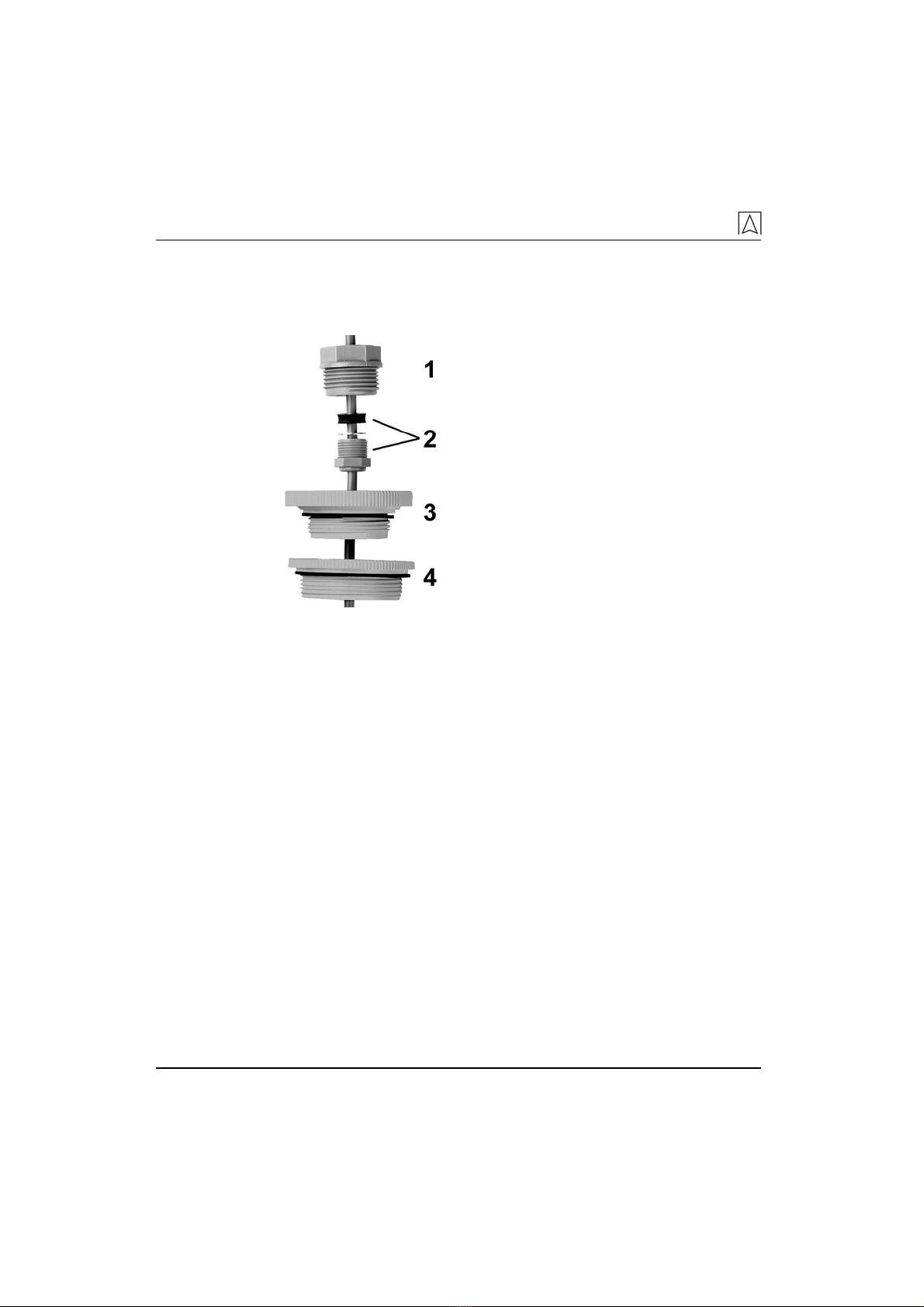
6.3 Installing the submersible probe
1Spacer
2Star
3Pressure sensor
1. Plug the star onto the pressure sensor. Watch out for the posi-
tion of the fins on the star.
2. Use the spacer to screw the star to the pressure sensor.
3. Suspend the submersible probe into the tank from the top.
4. Adjust the cable seat in the screw connection in such a way that
the probe tip just reaches the tank bottom. The measurement
hole in the submersible probe must not be in the oil sludge.
The amount of oil below the measurement hole of the sub-
mersible probe is not detected.
Installation
18 TankControl 01
6.4 Mounting the submersible probe to the tank
Screw connector kit
1. Free 1", 1½" or 2" connection in the tank: Mount and seal.
11" screw connector
2Used to fixate the cable
31½" screw connection
42" screw connector
Fig. 6: Mounting to tank with screw connector kit
2. Tighten the connector so that the cable can no longer move and
that the connection is smell-tight.

Installation
TankControl 01 19
Mounting kit
1PG 9 cable gland
2Mounting flange
Fig. 7: Mounting to tank with mounting kit
1. In a mounting flange with union nut, in a screwable cap or in a
free blind connection: Remove the mounting flange, the cap or
the blind connection from the tank and drill a 15 mm hole.
Never drill holes into the tank.
Make sure no chips can get into the tank when drilling.
2. Insert the enclosed PG 9 gland and fasten it with the enclosed
nut.
3. Fixate the cable of the submersible probe at the correct length;
make sure the connection is smell-tight.

Commissioning
20 TankControl 01
7 Commissioning
The accuracy of the measured values displayed depends on the ac-
curacy of the tank data determined and entered.
7.1 Password
In order to avoid inadvertent changes, a password must be entered
before changes can be made. After the entry, the password is active
for 15 minutes. For any later changes, the password must be entered
again.
The password is 186900. The password was deduced from the year
1869 when the company AFRISO was founded.
Fig. 8: Entering the password
Table of contents
Other Afriso EURO-INDEX Measuring Instrument manuals


