AG Neovo AIC U-17 User manual

AG Neovo U-17
service manual
Page of 59
1
Service Manual
AG Neovo (AIC U-17)
JUL,24
st
, 2009 Revision: 1.0
Issued By:
Checked By:
The release of this document is under control by the company. Any extra
copy of this document must be written permission by the product manager.
_________________________________________________________________________

AG Neovo U-17
service manual
Page of 59
2
※CONTENT
CHAPTER Page
A. WARNING 3
B. SAFETY PRECAUTIONS 3
1. DIMENSIONS 5
2. GENERAL INFORMATION 7
3. SPECIFICATIONS 9
4. THEORY OF OPERATION 19
5. CONTROL LOCATION 22
6. NECESSARY EQUIPMENT LIST 26
7. BLOCK DIAGRAM 27
8. CONDUCTOR VIEW 28
9. SCHEMATIC DIAGRAM 32
10. EXPLODED VIEW 40
11. TROUBLE SHOOTING HINTS 42
12. AUTO WHITE BALANCE PROCEDURE 45
13. BOM list 45

AG Neovo U-17
service manual
Page of 59
3
※ WARNING
This service information is designed for experienced repair technicians only
and is not designed for use by the general public.
It does not contain warnings or cautions to advise non-technical individuals
of potential dangers in attempting to service a product.
Products powered by electricity should be serviced or repaired only by
experienced professional technicians.
Any attempt to service or repair the product or products dealt within this
service information by anyone else could result in serious injury or death.
※SAFETY PRECAUTIONS
1. CAUTION
No modification of any circuit should be attempted. Service work should only be performed after you are thorough familiar with all of the following
safety checks and servicing guide lines.
2. SAFETY CHECK
Care should be taken while servicing this LCD display. Because the high voltage is used in the inverter circuit. These voltages are exposed in such
areas as the associated transformer circuits.

AG Neovo U-17
service manual
Page of 59
4
3. POWER SUPPLY REQUIREMENTS
The external power converter for this display utilizes AC and DC cords. AC cord is detachable,
But DC cord is permanently attached. Any attempt to replace another adapter could result in serious problem on the display.
4. LEAKAGE CURRENT HOT CHECK
4-1 Plug the AC cord directly into the AC outlet. Do not use an isolation transformer during this
check.
4-2 Connect a 1500 ohm, 10 watt resistor, paralleled by a 0.15uF capacitor between each metallic part and a good earth ground.
4-3 Use an AC voltmeter with 1000 ohm / volt or more sensitivity and measure the AC voltage across the combination 1500 ohm resistor and 0.15uF
capacitor.
4-4 Move the resistor connection to each exposed metallic part and measure the voltage.
4-5 Reverse the polarity of the AC plug in the AC outlet and repeat the above measurement.
4-6 Voltage measured must not exceed 1.5 volt RMS, from any exposed metallic part to the ground. A leakage current tester may be used in the
above hot check, in which case any circuit measured must not exceed 1 milliamp. In the case of a measurement exceeding the 1 milliamp value, a
rework is required to eliminate the chance of a shock hazard.
To Metal Parts
V
AC VOLTMETER
1500 10W
0.15u
.
Earth Ground
AG Neovo U-17
service manual
Page of 59
5
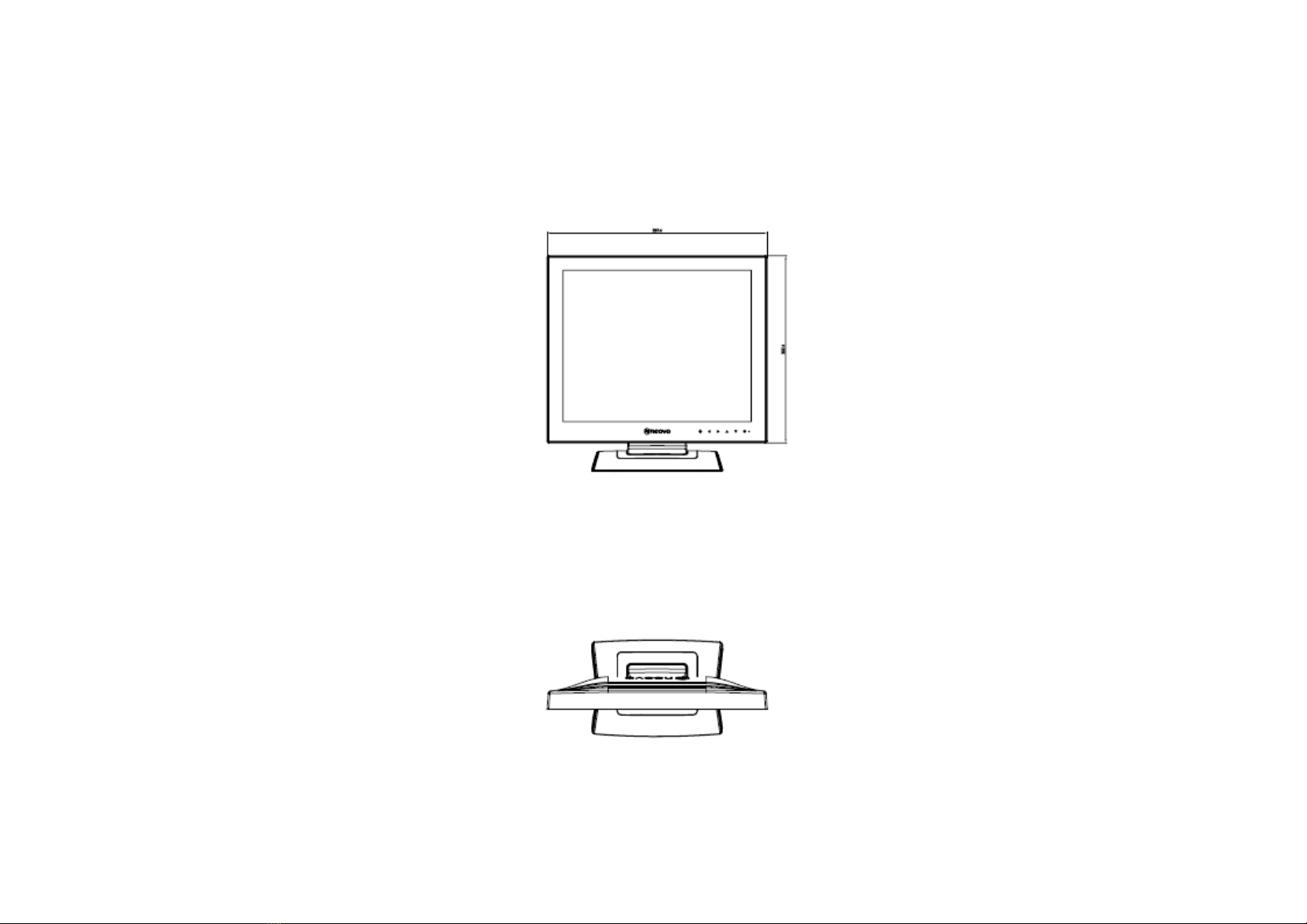
1. DIMENSIONS (Unit: mm)
1.1 Front View
1.2 Top View
1.3 Rear View

AG Neovo U-17
service manual
Page of 59
6
1.4 Side View

AG Neovo U-17
service manual
Page of 59
7
2. GENERAL INFORMATION
2.1 OUTLINE
The London U-17 Display With the protection of NeoV™ Optical Glass , a convenient headphone jack , and built-in speakers for ultimedia
applications ,the London Display is the utmost display for small offi ce/home office environments or progressive classrooms , training centres
and other milti-user spaces . The London U-17 Display is 17”High integration based Multi-mode supported high performance LCD monitor,This
monitor can be directly connected to general 15 pin D-sub VGA connector and DVI digital connector,eliminates therequirement of optional
special display card,It also supports VESA DPMS,EPA power management and plug & play function . There is a build-in stereo audio amplifier
with volume control to drive a pair of speakers.
2.2 FEATURES
2.2.1 Power Saving
Built in Power Saving function based on VESA DPMS standard. Power energy shall be saved
by controlling the circuit in accordance with power save signal from computer.
AG Neovo U-17
service manual
Page of 59
8
2.2.2 OSD (on screen display) function
OSD (12 Languages) function is excellent and new man-machine interface.
Anyone is able to set up the picture as the like through OSD menu.
2.2.3 Self Test function
Self Testing picture comes out by pushing any key in the case of no-connection with computer or power saving operation. This function shows
if monitor is alive or not and can be used for self aging test.
2.2.4 Ergonomic design
ISO 13406-2
2.2.5 Multi scan with digital technology
8 bit micro controller controls the circuit operation to meet with wide range signal of
Fh=24~81 kHz and Fv= 50~76 Hz.
2.2.6 Fine dot pitch
LCD panel with a fine dot pitch (Horizontal: 0.264 mm / Vertical: 0.264 mm)
2.2.7 Superior display performance
High contrast: Min. 600 : 1; Typ. 1000 : 1
High brightness: Min. 200 cd/m² Typ. 250 cd/m²
Wide view angle:
Minimum(10:1) Typical(10:1)
Value up 70° 80°
Value down 70° 80°
Value left 70° 85°
Value right 70° 85°
2.2.8 Special function
VESA
FPMPMI (Display Data Channel) Compatible

AG Neovo U-17
service manual
Page of 59
9
3. SPECIFICATION
3.1 OUTLINE
3.1.1 Front Indication: LED (Blue/Amber),POWER SW, Down,Up,LEFT, RIGHT, Auto key are located on the front panel.
3.1.2 15 pin mini D-SUB connector, 24 pin mini DVI connector, Audio line-in receptacle ,Power Switch ,USB connector and AC inlet are located on
the back cover.
3.1.3 OSD menu includes the following function. BRIGHTNESS, COLOR Setting , Image Setting , OSD setting , Audio Setting , Other Setting , Input
Setting , LANGUAGE, Information
3.1.4 VOLUME can be controlled with LEFT / RIGHT key
3.2. MECHANICAL SPECIFICATIONS
3.2.1 Dimension Height: 390 mm
Width: 397.4 mm
Depth: 173.7 mm
3.2.2 Net Weight: 5.7 kg
3.3. PANEL SPECIFICATIONS
Manufacturer AUO
Manufacturing country TW
ID no M170EG01 VG
Panel Technology TFT LCD
Resolution SXGA 1280 X 1024
Display surface Anti-glare
Pixel pitch in mm 0.264(H) x 0.264(V)
Power-inverter combo FSP025-1PI01B1
(TVI P/N AS51B2DSD08)
Scaler Realtek RTD 2525LH
Number of colors 16.7M colours
Backlight 2 CCFL

AG Neovo U-17
service manual
Page of 59
10
3.4. CONNECTORS
3.4.1 AC inlet: CEE22 typed connector
3.4.2 Audio: Line-in receptacle
3.4.3 Attached video signal /DDC 2: 15-pin D-sub and 24 Pin DVI connector
The PIN assignment of the 15 pin mini D-SUB connector / cable is as follows:
PIN Signal
1 Red
2 Green
3 Blue
4 Ground (open)
5 No Pin (ground)
6 Ground Red
7 Ground Green
8 Ground Blue
9 +5 V for DDC
10 Ground
11 Ground (open)
12 SDA (DDC Data)
13 H – Sync
14 V – Sync
15 SCL (DDC Clock)

AG Neovo U-17
service manual
Page of 59
11
The PIN assignment of the 24 pin DVI-D connector / cable is as follows:
PIN Signal
1 TMDS data2-
2 TMDS data2+
3 TMDS datB1 shield
4 NC
5 NC
6 DDC clock
7 DDC data
8 Not connected
9 TMDS data1-
10 TMDS data1+
11 TMDS data1 shield
12 NC
13 NC
14 +5V
15 Ground (return for +5 V and H/V sync)
16 Hot plug detect
17 TMDS data0-
18 TMDS data0+
19 TMDS data0 shield
20 NC
21 NC
22 TMDS clock shield
23 TMDS clock+
24 TMDS clock-
3.5 ELECTRICAL SPECIFICATIONS
AG Neovo U-17
service manual
Page of 59
12
3.5.1 Standard conditions
•Test mode: 1280 x 1024 at 60 Hz
•Test condition: Dark room with ambient illumination < 1 cd/ m2
•Picture size : Set automatically to full screen
•Warm up time : At least 30 min.
•AC supply voltage: 230V/50Hz
•Ambient temperature: 25°C ± 5°C
•Viewing distance: 50 cm
•Humidity: 10% to 85%
•Brightness: Set to standard condition
•Video input signal: 700mVpp (analog) 3,3V TMDS(digital)
3.5.2 POWER
3.5.2.1 Power supply
•A/C Line voltage range: 90 V - 264 V
•A/C Line frequency range: 47 Hz - 63 Hz
•Input current: ≤2.0 A
•Inrush current: Shall be less than the ratings of critical components(including
fuse, rectifiers and surge limiting device) for all conditions of
line in voltage.
•Maximum power cons.: 25 Watts (including consumption on USB interface)
3.5.2.2 Power Management
Mode H-SYNC V-SYNC Power-cons. Indication Rec. time
Power-On Active Active < 25 W Green --
Off-state Inactive Inactive < 1 W Amber 2s
Switch-off Inactive Inactive < 0.8 W Dark 2s
AG Neovo U-17
service manual
Page of 59
13
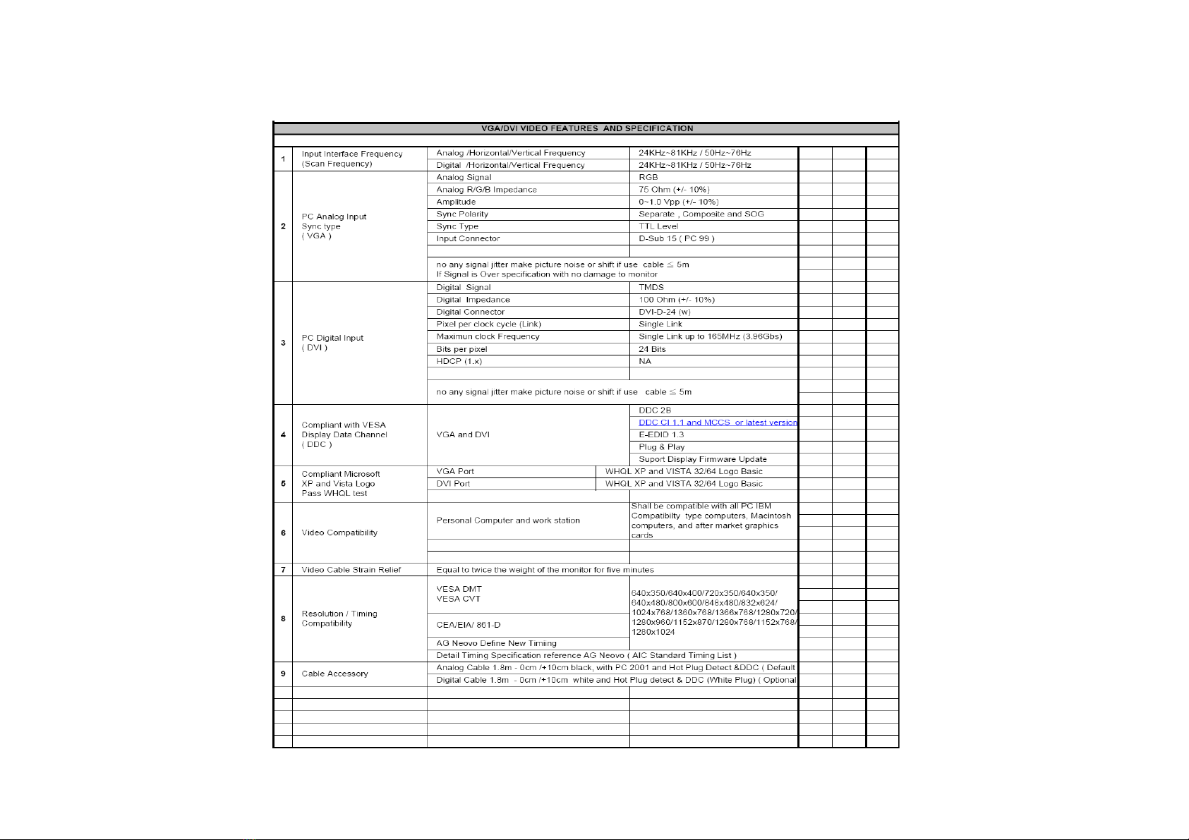
3.5.3 Signal level and input impedance
3.5.3.1 VGA/DVI Video features and Specification

AG Neovo U-17
service manual
Page of 59
14
3.5.2 Audio Technical Description and Specification

AG Neovo U-17
service manual
Page of 59
15
3.5.3 Optical Image Performance Features and Specification

AG Neovo U-17
service manual
Page of 59
16
3.5.4 Display Area
Display area: 337.9 mm x 270.6 mm
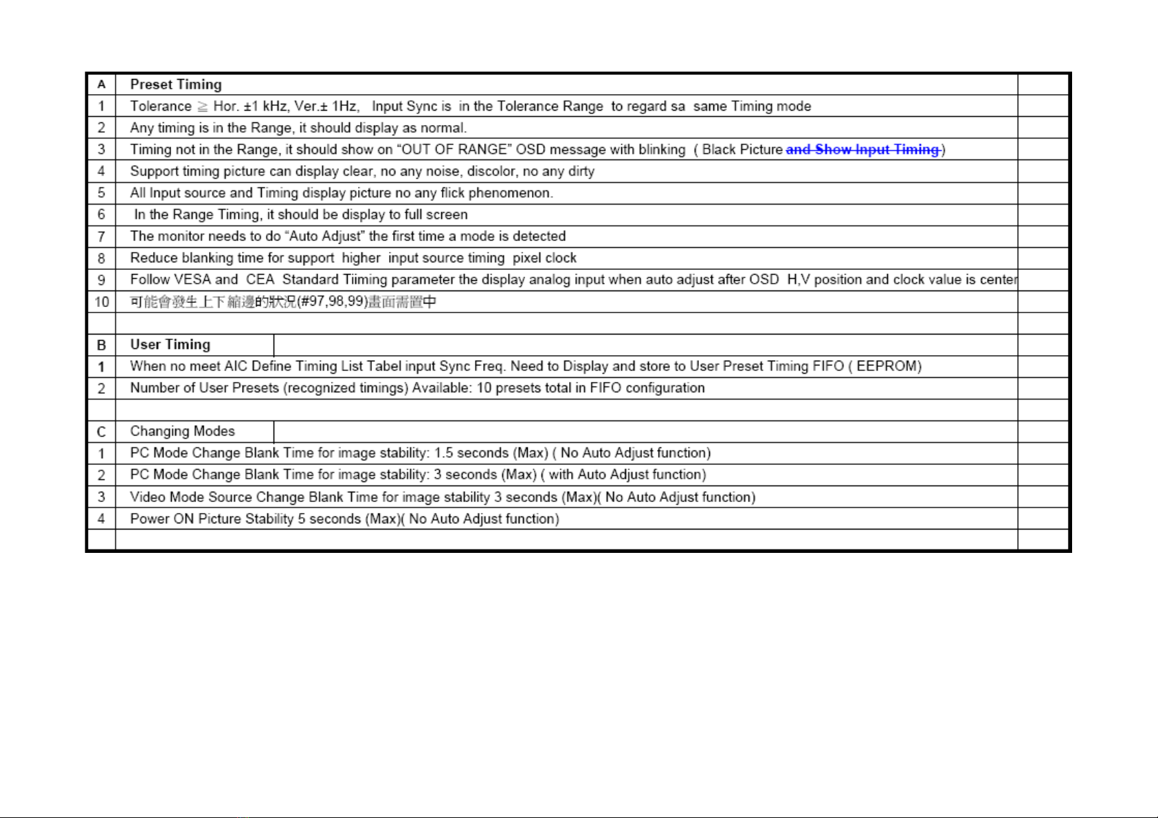
3.5.5 Timings List
AG Neovo U-17
service manual
Page of 59
17
3.6 REGULATORY STANDARDS
3.6.1 Safety standards
This monitor applies to various safety & EMI standards May refer to the logo label

AG Neovo U-17
service manual
Page of 59
18
3.6.2 Safety approvals
UL/cUL
FCC
CB
CE
BSMI
EUP
Energy Star(EPA5.0)
RoHS
WEEE
REACH
3.7. SIGNAL CABLE
Signal cable with Mini D-Sub 15P connectors. Length: 1.8 meter.
Signal cable with Mini DVI-D 24P connectors. Length: 1.8 meter.
3.8. RELIABILITY
> 50000hrs (demonstrated MTBF)

AG Neovo U-17
service manual
Page of 59
19
4. THEORY OF OPERATION
This section describes the function of the LCD monitor per functional block.
L7AM-A1 monitor includes main Board (including audio and earphone board inside), power board and button board and USB board
4.1 Main BOARD
The main board is a two-layers, single-landed design with ground and ground planes provided. The VGA and DVI cable are the cables that contain
video signal, sync signal and DDC signal from PC VGA and DVI adapter This system board consists of 3 functional areas : flat panel controller,
Micro controller and APA2069JI-TUL audio controller
4.1.1 Flat panel controller… RTD2525LH (U7)
The heart of the system board is RTD2525LH. The RTD2525LH is a graphics processing IC for LCD monitor. It provides some control functions
required for LCD panel. On-chip functions include a high-speed triple-ADC , PLL, high scaling engine and OSD controller.
a) Clock Generation :
Crystal Input Clock (XIN and XOUT). This is the input pair to an internal crystal oscillator and corresponding logic. 24 MHz crystal are
recommended.
b) Hardware Reset ( Pin 4 )
Hardware Reset signal is generated by Pin 4.It assert a reset signal at east 1 ms.
c) Analog to Digital Converter
The RTD 2525LH chip has three ADC's (analog-to-digital converters), one for each color (red, green and blue) . The analog RGB signals are
connected to RTD2525LH as described below
AG Neovo U-17
service manual
Page of 59
20
Pin Name Pin Number
Red+ 16
Red- 15
Green+ 14
Green- 13
Blue+ 12
Blue- 11
d) Panel LVDS interface (Pin 25~36)
The RTD2525LH driver interface is highly programmable. It supports LVDS port for panel.
4.1.2 Micro controller……
The RTD2120 microcontroller serves as the system microcontroller. That is , it programs the RTD2120 and manages other devices in the
system such as the keypad, the backlight, LED and APA2069JI-TUL audio general purpose input/output pins.
Pin number Pin name Pin function
1 P5.5/PWM5 VOLUME
4 RST RESET
11 P3.4/T0 HDCP_SCL
12 P3.5/T1 HDCP_SDA
13 P7.6/CLK02 LED-G
14 P7.7 LED-R
20 P6.0/ADC0 Key1
21 P6.1/ADC1 Key2
22 P6.2/ADC2 DDC_WP
24 P6.4 PWR
44 P5.0/PWM0 VGA DET
45 P5.1/PWM0 DVI DET
Table of contents
Other AG Neovo Monitor manuals

AG Neovo
AG Neovo SC-32E User manual

AG Neovo
AG Neovo X-22E User manual

AG Neovo
AG Neovo RX-W22 User manual

AG Neovo
AG Neovo DW Series User manual

AG Neovo
AG Neovo SX-17 User manual

AG Neovo
AG Neovo E-17 User manual

AG Neovo
AG Neovo U-17 User manual

AG Neovo
AG Neovo TS-17R User manual

AG Neovo
AG Neovo PN-46D User manual

AG Neovo
AG Neovo H-W22 User manual

AG Neovo
AG Neovo PF-55H User manual

AG Neovo
AG Neovo MD-24 User manual

AG Neovo
AG Neovo C-17P User manual

AG Neovo
AG Neovo PD-42 User manual

AG Neovo
AG Neovo LW-22G User manual

AG Neovo
AG Neovo SC-2202 User manual

AG Neovo
AG Neovo F-17C User manual

AG Neovo
AG Neovo X-15E User manual

AG Neovo
AG Neovo E-W22 Instruction Manual

AG Neovo
AG Neovo SX-15 User manual


