AG SPRAY LA9000 Manual

LIQUID
APPLICATOR
LA9000
operation & maintenance manual
SHOP ONLINE @
WWW.AGSPRAY.COM
COLUMBUS, NE
402.564.4544
NEWTON, KS
316.283.4444
BAKERSFIELD, CA
661.391.9081
TEMPE, AZ
480.705.8047
OTHELLO, WA
509.488.6631
HOPKINSVILLE, KY
270.886.0296
DOTHAN, AL
334.673.0580
GREENWOOD, MS
662.453.4524
FARGO, ND
701.280.2862
MANKATO, MN
507.388.6295
MANUFACTURING
QUALITY PRODUCTS
FOR 30 YEARS
1650 OR 1950 GALLON tank w/ 27’, 30’, 35’, 40’ or 55’ toolbar

LA9000 LIQUID APPLICATOR OPERATION & MAINTENANCE MANUAL2
3INTRODUCTION
3PRE-OPERATION CHECKLIST
4PLACING IN STORAGE
4REMOVING FROM STORAGE
5LIMITED WARRANTY
6-9OPERATING INSTRUCTIONS
10 BREAK-IN
10 SERVICE AND MAINTENANCE
11 GREASING
12-39 BREAKDOWNS
TABLE OF CONTENTS

SHOP ONLINE @ WWW.AGSPRAY.COM 3
1. Read and understand the Operators Manual and all
safety signs before using.
2. Place all controls in neutral, stop tractor engine, turn
monitor off, set park brake, remove ignition key, wait
for nozzles to stop spraying before servicing,
adjusting, or repairing.
3. Before using it in a field, be familiar with all potential
hazards: trees, rocks, ditches, gullies, etc. Plan the
spraying route to avoid hazards. Remember you are
driving a wide machine. USE CAUTION WHEN
CORNERING.
4. Keep hands, feet, hair and clothing away from all
moving and/or rotating parts.
5. Do not allow riders on the applicator or tractor during
operation or transporting.
6. Clear the area of all bystanders, especially children,
before starting or filling with water or chemical.
7. Stay away from wing pinch points when folding or
extending wings. Keep others away.
8. Stay away from power lines when extending or
folding wings. Electrocution can occur without
direct contact.
13. In case of poisoning, get immediate medical attention.
15. Do not eat in the field when side dressing.
16. Before applying pressure to the hydraulic system,
make sure all components are tight and that steel
lines, hoses and couplings are in good condition.
17. Before applying pressure to fertilizer system make
sure that all connections are tight and that all hoses
and fittings are in good condition.
18. Review safety instructions annually.
INTRODUCTION
Before operating the Applicator and each time thereafter, the
following areas should be checked off:
1. Lubricate the machine per the schedule outlined in
the “Maintenance Section”.
2. Use only a tractor of adequate power and weight to
operate the Applicator.
3. Ensure that the machine is properly attached to the
tractor. Be sure that a mechanical retainer is installed
through the drawbar pin and the safety chain is
attached to the drawbar cage. Jack is in full up
position.
4. Check the hydraulic system. Ensure that the
hydraulic reservoir in the tractor is filled to the
required specifications.
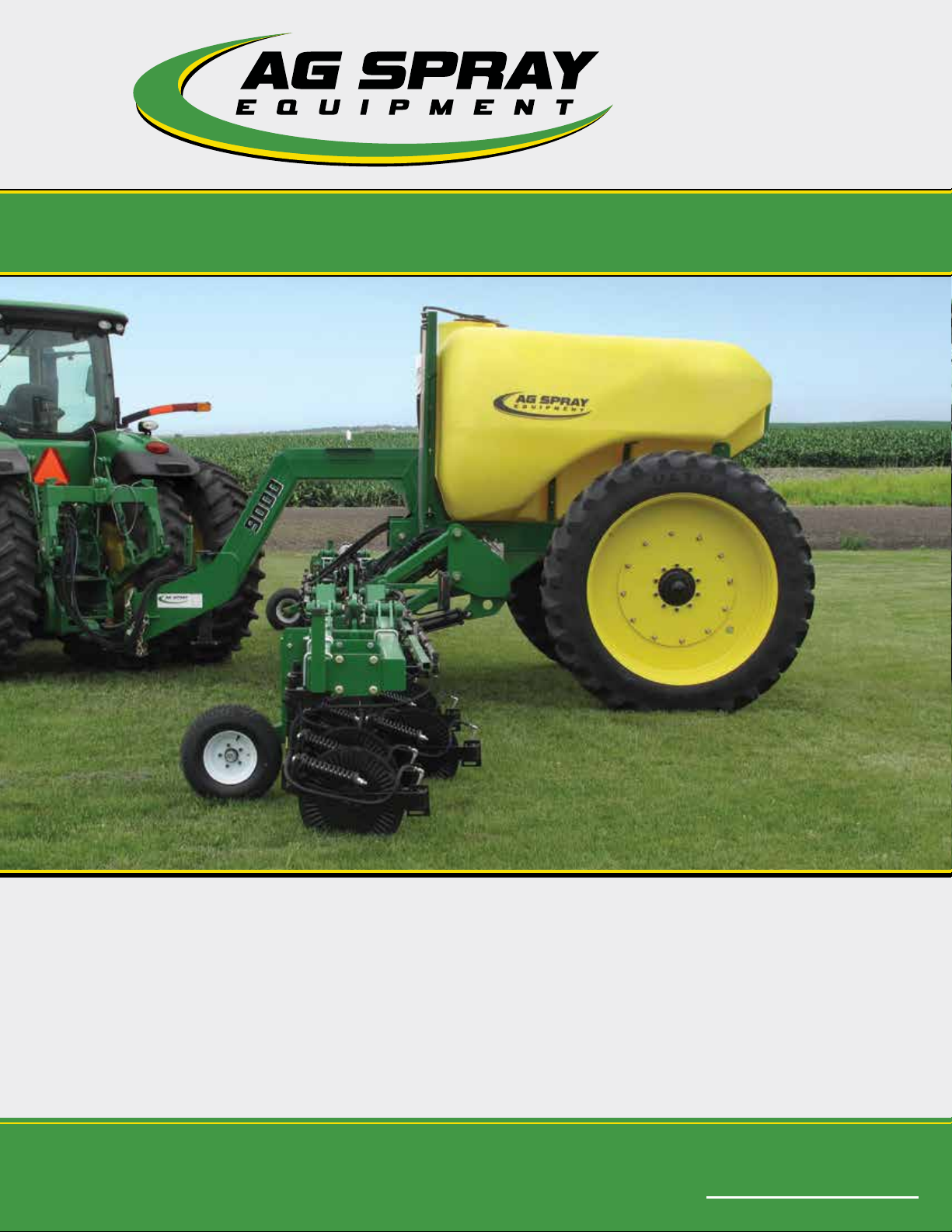
5. Inspect all hydraulic lines, hoses, fittings and couplers
for tightness. Use a clean cloth to wipe any
accumulated dirt from the couplers before
connecting to the hydraulic system of the tractor.
6. Check the tires and ensure that they are inflated to
the specified pressure.
7. Calibrate the Applicator if it is the start of the season
or a new chemical is being used. Calibrate as
specified in rate control manual.
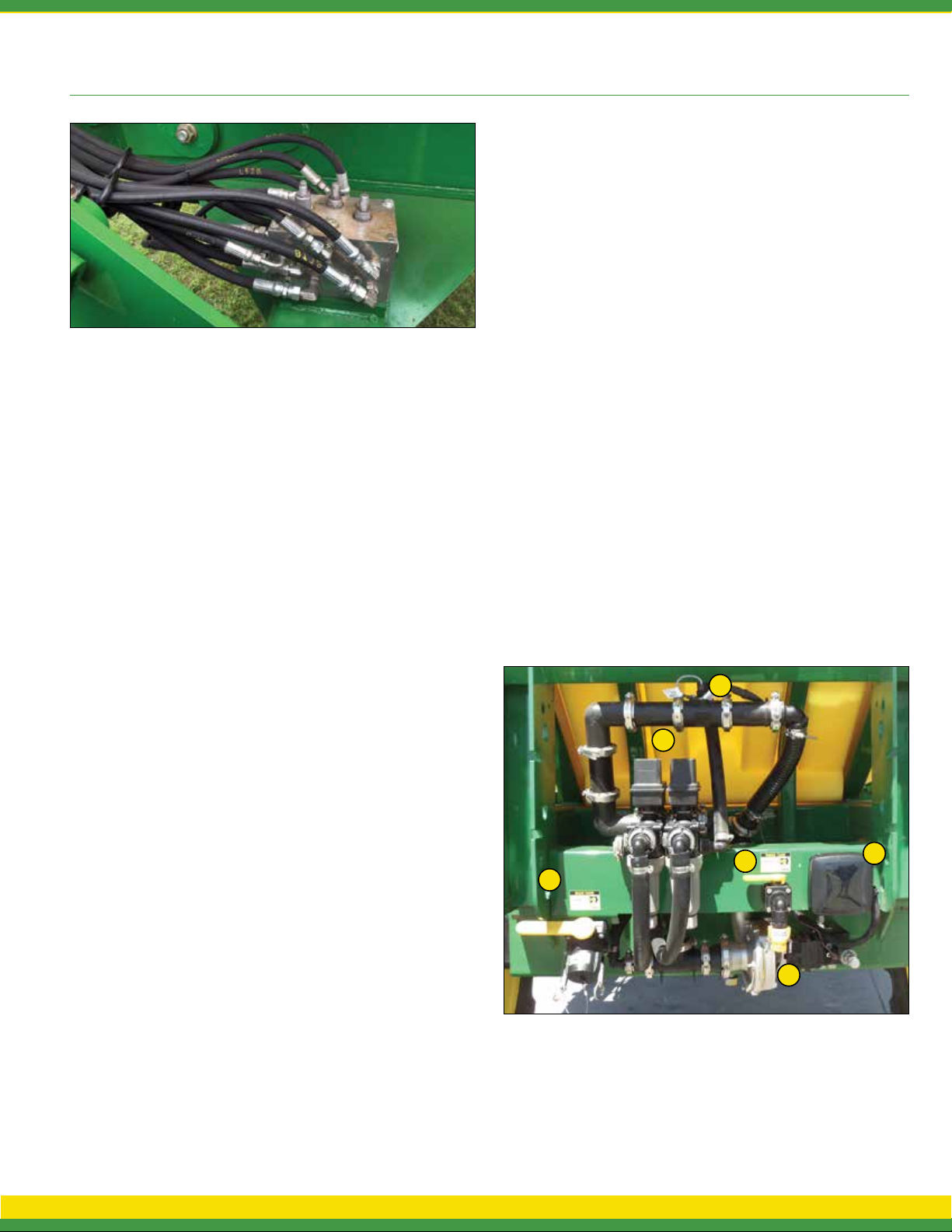
8. Check the condition and routing of all chemical hoses
and lines. Replace any that are damaged. Re-route
those that are rubbing pinched or crimped.
9. Check the spray pattern of each nozzle. Remove and
clean or replace any that have an unusual pattern.
10. Remove the steel mesh line filters and wash with
clean water. Reinstall.
11. Check that all connections in the electrical system are
connected and tight.
13. Before unfolding boom remove transport wing lock
pins (Figure 7) and tower cylinder Transport stop
(Figure 6) Reinstall lock pins and tower stop
before parking sprayer.
PRE-OPERATION CHECKLIST

LA9000 LIQUID APPLICATOR OPERATION & MAINTENANCE MANUAL4
g. Remove nozzles from boom Disassemble and
wash nozzle, Spring, diaphragm and housing.
Store inside.
4. Lubricate all grease points. Make sure all grease
cavities have been filled with grease to remove
any water residue from the washing.
5. Inspect all the hydraulic hoses, couplers and fittings.
Tighten any loose fittings. Replace any hose that
is badly cut, nicked, abraded or is separating from
the crimped end of a fitting.
6. Inspect all the spray hoses and fittings. Tighten any
loose fittings. Replace any hose That is badly
cut, nicked, abraded or is separating from a fitting.
7. Touch up all paint nicks and scratches to prevent
rusting.
**STORAGE SAFETY**
1. Store unit in an area away from human activity.
2. Do not permit children to play on or around the
stored applicator.
3. Unhook and store in the transport configuration.
At the end of the spray season, the machine should be
thoroughly inspected and prepared for storage. Repair or
replace any worn or damaged components to prevent any
unnecessary down time at the beginning of the next season.
Follow this procedure:
1. Thoroughly wash the machine using a hose or a
pressure washer to remove all dirt, mud, debris or
residue.
2. Thoroughly wash the inside of the tank.
3. In climates that encounter freezing temperatures
during the storage period, the following
preparation should be done:
a. Add 10 gallons (40 liters) of a potable RV
antifreeze to the tank.
b. Run unit for 5 minutes in the spray cycle to
circulate solution to all parts of the circuit.
c. While circulating the fluid, open and close all the
valves in the system to flush all the water from
the system.
e. Flush the solution out the booms.
f. Open all disconnects and drain hoses, pumps,
filters, solenoids and tanks.
PLACING IN STORAGE
When removing from storage and preparing to use,
follow this procedure.
1. Clear the area of bystanders, especially small
children, and remove foreign objects from the
machine and the working area.
2. Check
a. Tank for cracks
b. Tank hold down hardware
c. All hardware. Tighten as required.
d. Tire pressure.
e. All sprayer and hydraulic lines, fittings and
connections. Tighten as required.
REMOVING FROM STORAGE
3. Lubricate all grease fittings.
4. Replace any defective parts.
5. Fill the tank with 20 gallons (75 liters) of clean water
and run for 5 minutes. Open and close all valves
several times. Flush water through the booms.
6. Repeat step 5.
7. Calibrate the pump, nozzles and sprayer before using.
8. Go through the pre-operation checklist before using.

SHOP ONLINE @ WWW.AGSPRAY.COM 5
LIMITED WARRANTY
Ag Spray Equipment warrants to the buyer that the new
machinery is free from defects in material and workmanship.
This warranty is only effective as to any new machinery which
has not been altered, changed, repaired or treated since its
delivery to the buyer, other than by Ag Spray Equipment or
its authorize dealers or employees, and does not apply to
accessories, attachments, tools or parts, sold or operated with
the new machinery, if they have not been manufactured by Ag
Spray Equipment.
Ag Spray Equipment shall only be liable for defects in the
materials or workmanship attributable to faulty material or bad
workmanship that can be proved by the buyer, and specifically
excludes liability for repairs arising as a result of normal wear and
tear of the new machinery or in any other manner whatsoever,
and without limiting the generality of the foregoing, excludes
application or installation of parts not completed in accordance
with Ag Spray Equipment operator’s manual, specifications or
printed instructions.
Written notice shall be given by registered mail, to Ag Spray
Equipment within seven (7) days after the defect shall have
become apparent or the repairs shall have become necessary,
addressed as follows: Ag Spray Equipment, 5834 East 23rd
Street, Columbus, NE 68601.
This warranty shall expire 2 years after the date of delivery of
the new machinery.
If these conditions are fulfilled, Ag Spray Equipment shall at
its own cost and at its own option either repair or replace any
defective parts provided that the buyer shall be responsible
for all expenses incurred as a result of repairs, labor, parts,
transportation or any other work, unless Ag Spray Equipment
has authorized such expenses in advance.
The warranty shall not extend to any repairs, changes, alterations,
or replacements made to the new equipment other than by Ag
Spray Equipment or its authorized dealers or employees.
This warranty extends only to the original owner of the new
equipment.
Rubber parts are not warranted. (including tires, hoses,
grommets)
This warranty is limited to the terms stated herein and is in lieu
of any other warranties whether express or implied, and without
limiting the generality of the foregoing, excluded all warranties,
express or implied or conditions whether statutory or otherwise
as to quality and fitness for any purpose of the new equipment.
Ag Spray Equipment disclaims all liability for incidental or
consequential damages.
This sprayer is subject to design changes and Ag Spray Equipment
shall not not be required to retro-fit or exchange items on
previously sold units except at its own option.
MANUFACTURING
QUALITY PRODUCTS
FOR 30 YEARS

LA9000 LIQUID APPLICATOR OPERATION & MAINTENANCE MANUAL6
1. Ensure applicator is connected securely to tractor draw bar
with clevis pin and safety chain. (See Figure 1).
2. Connect applicator hydraulic hoses to the tractor remote
couplers. The blue hoses are for the main bar height control.
The green hoses are for the outside wing fold. The yellow
hoses are for main wing fold on 35’ through 55’ bars. The
red hoses are for the hydraulic pump (Figure 2).
3. Connect wiring harness if using hydraulic pump with rate
control.
4. Grease Applicator (Refer to Mainentance).
5. Before road travel, install all locking collars on toolbar
cylinders and safety pins on wings.
OPERATING INSTRUCTIONS
6. Remove locking collars as needed to maintain a depth
of 4 to 5 inches. Constant down pressure on main lift is
not recommended (weight of toolbar will keep unit in
the ground). Leave hydrualic selector in neutral for field
operation.
7. Remove safety pins on wing cylinders. Wing cylinders
remote will run in constant while down (Figure 4).
The Applicator is equipped with adjustable down pressure relief
valve on wing cylinders. The valve is preset at 800 PSI. This may
be adjusted as needed. The relief valve is located on drivers side
of linkage arm mount, and requires an allen wrench to adjust
(clockwise to increase pressure and counterclockwise to decrease
pressure. Figure 5).
FIG. 4
FIG. 1
FIG. 5
FIG. 3
FIG. 2

SHOP ONLINE @ WWW.AGSPRAY.COM 7
c. Close and lock down the bypass adjusting screw in the
hydraulic motor (if applicable).
Switch rate controller to manual and press the “+” button on
TeeJet or “Increase” button on Raven, hold for 8 seconds. Then
press the “-” button on TeeJet or “Decrease” button on Raven
for 4 seconds.
Set the tractor hydraulic flow control valve for minimum
hydraulic oil flow to the remote outlet (Tortoise position).
Start the tractor and allow the hydraulic oil to circulate for
approximately 10 to 15 minutes or until adequately warmed.
Prime the centrifugal pump with all valves open.
Open the sprayer PWM (pulse width modulation) valve on rate
controller and the boom shut-off valves.
Slowly adjust the tractor hydraulic flow control valve until the
desired boom pressure is attained.
NOTE: See manufacturerpump operators manual for further
setup and maintenance.
NOTE: See specific rate controller manual for further setup and
maintenance.
8. After unfolding main wing, engage hydraulic lever in
“constant pressure.” This is necessary to allow wings to
maintain constant depth and follow uneven terrain, as well
as the ability to “gullwing” (Lift both wings evenly when
turning).
9. Field Operation: When you come to the end of the field.
1. Lift main section
2. Pull back on main wing lever long enough to lift both
wings slightly (“gullwing”).
3. After turning, lower main section and wing section
and return wing hydraulics to constant pressure.
4. Main section must be lifted to maximum height to
hold gullwing.
10. Check and clean screens as needed.
11. Pump Settings
Optional Ground Drive Pump
11a - Remove tranport pin
11b - Use John Blue pump setting slide chart. Loaded radius is
9.75 and sprocket ratio is 32 drive and 18 driven.
11c - Set pump to recommended setting.
Optional Hydraulic Drive Pump
a. Hydraulic pump hoses supplied on the applicator
include (1) 1/2” line and (1) 3/4” line. The 1/2” hose
is the hydraulic supply (in/pressure) and the 3/4”
hose is the return (out/non-pressure).
NOTE: It is recommended for optimal pump performance that
the 3/4” return line connect directly to the tractor hydraulic
reservoir (not tractor SCV port). Doing so eliminates possible
back pressure restriction on the 3/4” return line. Excessive
back pressure restriction can cause hydraulic orbital motor
damage/failure.
b. Proper hydraulic pump disengagement. When shutting
off the pump, move the selector to the FLOAT position
to allow the centrifugal pump to come to a gradual stop.
Standard spool valves, which are found on all tractor
hydraulic systems, can cause potentially damaging high peak
pressures in the hydraulic system when closed, because of
abrupt shutoff of oil flow in both the supply and return lines.
OPERATING INSTRUCTIONS
12. Plumbing (See Figure 6)
a. Main Tank Fill Valve (3” Quick Fill)
b. Rinse Tank Fill Valve (Garden Hose Fitting)
c. PWM Control Pump (93100-001)
d. Electrical Junction Box
e. Section Control Valves (450BEC-FB Series)
f. Flow Meter (RFM60P)
FIG. 6
a
b
c
d
e
f

LA9000 LIQUID APPLICATOR OPERATION & MAINTENANCE MANUAL8
440/450 Raven Controller With PWM Setup
1. Install Raven 440 or 450 control console and hook up to sprayer (see instructions inside controller
box).
2. Turn on control console.
When making selections/entering numbers, always be sure to press enter to save your settings.
3. Make the following selections when prompted:
- Units US (Enter)
- Speed sensor 2 “SP2” (Enter)
- Valve type C-P “Closed PWM” (Enter)
4. Select Boom Cal “Raven 440, 1-3”, “Raven 450, 1-5”
- Enter number of inches covered for each section (not full width of boom).
To find the number of inches covered, multiply the number of nozzles per section and the number
of inches between nozzles. (Ex. Section one; 12 nozzles x 20 inch between nozzles =240 inches)
5. Select Speed Cal
- Enter 783 (This is the cal number for a Garmin GPS Sensor).
6. Select Meter Cal-Enter the meter cal number which is printed on the tag for on your Flow Meter.
(ex. 720)
7. Select Valve Cal
- Enter 43 (This is only for use with the PWM controlled hydraulic pump).
8. Select Rate 1
- Enter the number of gallons/acre you want to spray in Rate 1. (ex. 10.0)
9. Select Rate 2-Enter the number of gallons/acre you want to spray in Rate 2. (ex. 20.0)
10. Select DATA MENU
- Scroll to PWM Frequency and enter 110.
11. Hold SELF TEST
- This will scroll through all settings to make sure everything is entered.
- If all cal numbers are entered, it will stop scrolling after a few seconds. (move to step 12.)
- If any cal numbers have not yet been entered, it will keep scrolling. (If so, you will need to go
back through your cal numbers and make sure they are all entered correctly.)
12. Turn the Flow Control to MAN for manual control, turn the Booms all to the off position and turn
the master on.
13. Hold INC to build pressure. This will allow you to check any leaks and use your inductor tank (if
applicable) while sitting. BE AWARE NOT TO OVER PRESSURIZE SYSTEM
14. TO SPRAY
- Turn the Flow Control to Rate 1 or Rate 2 (preference).
- The speed you need to travel is dependent on the rate at which you are spraying.

SHOP ONLINE @ WWW.AGSPRAY.COM 9
2630 JD Rate Controller With PWM Setup
1. After hooking up all wiring between tractor and sprayer, turn the system on.
2. Make sure all nozzles are open with desired tips installed.
3. From the Menu, select Rate Controller
4. Setup your Implement type
- Select Pull Behind Sprayer, enter a name and tank size.
5. Select the Setup Tab (right)
6. Select the Implement Tab (top)
- Enter your boom width
- Adjust the width of each section
- Be sure to enter any Fence Row(s) if applicable
7. Select the System Tab (top)
- Section Valve type – 3 wire
- Constant Flow – no
- Control Valve Type – PWM
8. Select PWM Setup
- Control Valve Calibration – 2743
- Coil Frequency – 110
- High Limit – 100
- Low Limit – 1
9. Select Calibrate PWM
- Turn Master ON and press Start
- Decrease if necessary to make sure Low limit is at or around 1 gal/min. Set Low Limit
- Increase if necessary to make sure High limit is at or just below max pump rotation or 80 psi.
Set High Limit and turn off Master.
- If you return to PWM Setup it may show new numbers in the High Limit and Low Limit.
10. Setup your Flowmeter
- Flowmeter Calibration – Enter the Flowmeter cal. number located on your flow meter.
- Flowmeter Units – 10 Gal.
11. Select the Rates Tab (top)
- Set your rates at gal/acre.
12. Select the Diagnostics Tab (right)
- From the dropdown menu under the Tests tab, select Nozzle Flow Check
- Enter your desired speed into the Test Speed
- Enter your desired Gal/Acre into the Rate
- Turn the Master on and press Start to test
(At this point you can see the system will adjust its self to run at the desired speed while you are
not driving.)

LA9000 LIQUID APPLICATOR OPERATION & MAINTENANCE MANUAL10
Although there are no operational restrictions on the applicator
when used for the first time, it is recommended that the
following mechanical items be checked:
A. After operating for 1/2 hour
1. Re-torque all the wheel bolts.
2. Re-torque all other fasteners and hardware.
3. Check that all electrical connections are tight.
4. Check that no fertilizer or hydraulic lines are
being pinched or crimped. Re-align as required.
5. Check that all nozzles are working properly.
Clean or replace as required.
6. Lubricate all grease fittings.
B. After 5 hours and 10 hours of operation
1. Retorque all wheel bolts, fasteners and hardware.
2. Check fertilizer and hydraulic line routing.
3. Check that all nozzles are working properly.
4. Then go to the normal servicing and maintenance
schedule as defined in the Maintenance Section.
5. Lift right hand side of machine and check main wheel
bearing for proper play (slight wobble when pulling on top of
wheel). Repeat for left hand side.
! MAINTENANCE SAFETY !
1 Review the Operator’s Manual and all safety items
before working with, maintaining or operating the
Applicator.
BREAK-IN
SERVICE AND MAINTENANCE
2. Place all controls in neutral, stop the tractor engine,
turn monitor off, set park brake, remove ignition key,
wait for nozzles to stop spraying before servicing,
adjusting, repairing or unplugging.
3. Follow good shop practices:
- Keep service area clean and dry
- Be sure electrical outlets and tools are properly
grounded
- Use adequate light for the job at hand.
4. Before applying pressure to a hydraulic system, make
sure all components are tight and that steel lines,
hoses and coupling are in good condition.
5. Before applying pressure to fertilized system, make
sure that all connection are tight and that all hoses
and fittings are in good condition.
6. Install wing lock pins and tower stops before relieving
pressure from hydraulic circuit to service Applicator.
7. Keep hands, feet, clothing and hair away from all
moving and/or rotating parts.
8. Clear the area of bystanders, especially children,
when carrying out any maintenance and repairs or
making any adjustments or filling.
9. Place stands or blocks under the frame before
working beneath the machine.
10. Wear safety goggles, neoprene gloves and protective
clothing when working on the Applicator filled with
active chemical.
11. Wash machine to remove all chemical residue before
working on unit. Wear appropriate protective gear at
all times.
12. Protect yourself from chemical contamination.

SHOP ONLINE @ WWW.AGSPRAY.COM 11
- Wipe grease fitting with a clean cloth before greasing
to prevent injecting dirt and grit into joint.
- Replace and repair broken fittings immediately.
- If a fitting will not take grease, remove and clean
thoroughly. Also clean lubricant passageway.
Replace fitting if necessary.
*Note: Grease 20 points 8 hours or daily. Along
with 2 points per coulter. Hubs and spindles should
be greased biannually.
*Note: It is best to grease the machine at the end
of the day to ensure that fertilizer/chemicals do not
have time to start corroding parts.
GREASING
L/R GREASE LOCATIONS
Apply adequate grease to the following:
1. L/R Main Wing Hinge (Fig. 20b)
2. L/R Flip Wing (35’ and 40’) (Fig. 20c)
3. Coulter Pivots (Fig. 20d)
4. Parallel Hinge Bushings (Fig. 20a)
5. Piston Pump (Refer to pump operators manual)
FIG. 20a
4
4
4
FIG. 20b
1 1
FIG. 20c
2
2
2
2
FIG. 20d
3
3
4

LA9000 LIQUID APPLICATOR OPERATION & MAINTENANCE MANUAL12
16
3
5
22
24 21
15 125 18
27
14
6
19
26
11
28
12
Item
No
Part
Number
Qty.
Descripon
15006363 12
1"-8nc Hex Flanged Toplock Nut Gr. 8
25006365 4
1/2-13nc Hex Flanged Toplock Nut Gr. 8
35006366 8
3/8-16nc Hex Flanged Toplock Nut Gr. 8
45034482 1
3/8"-16nc x 1" lg Carriage Bolt
55034544 4
3/8"-16nc x 2 1/2" lg (Full Thread) Carriage Bolt
65034743 2
Flng HH Bolt 3/4-10 X 6"
75034750 8
Flng HH Bolt 1-8 X 3"
85034755 2
Flng HH Bolt 3/4-10 X 3 1/2"
95034761 4
Flng HH Bolt 1/2-13 X 1 1/2"
10 50347643
Flng HH Bolt 3/8-16 X 1"
11 50464454
TUBE CAP, 2x2x3/16" WALL
12 51171044
1/2-13 x 1 1/2" Square Head Cup Point Set Screw
13 52787251
VALVE MOUNTING BRACKET
14 52792431
WLDMT, FRAME
15 52793724
WLDMT, APPLICATOR GOOSENECK ATTACH PIN
16 52793741
WLDMT, 1650 TANK HOLD DOWN
17 52793811
WLDMT, LARGE TANK HOLDDOWN ATTACH RH
18 52793821
WLDMT, LARGE TANK HOLDDOWN ATTACH LH
19 52793881
WLDMT, LARGE TANK REAR HOLD DOWN
20 52800271
1650 SIGHT GAGE ANGLE W/GRADUATIONS
21 52805734
TUBE, SPACER HAND RINSE TANK
22 52805821
PLATE, LOGO 1950
23 52805841
BRACKET, SIGHT GAGE UPPER MOUNT
24 52806031
PLATE, 1950 HAND WASH TANK/LOGO
25 52808032
WLDMT, LARGE SPRAYER GOOSENECK ATTACH
26 52808061
ASSY, LARGE GOOSENECK
27 52808721
WLDMT, LIFTARM MOUNT TUBE
28 52808854
WLDMT, TANK SUPPORT
5280877 - APPLICATOR FRAME FOR 1650 TANK

SHOP ONLINE @ WWW.AGSPRAY.COM 13
1
7
3
5
22
24
16
19
6
14
27
26 25
1
15
18
21
11
28
12
Item
No
Part
Number
Qty.
Description
15006363 12
1"-8nc Hex Flanged Toplock Nut Gr. 8
25006365 4
1/2-13nc Hex Flanged Toplock Nut Gr. 8
35006366 8
3/8-16nc Hex Flanged Toplock Nut Gr. 8
45034482 1
3/8"-16nc x 1" lg Carriage Bolt
55034544 4
3/8"-16nc x 2 1/2" lg (Full Thread) Carriage Bolt
65034743 2
Flng HH Bolt 3/4-10 X 6"
75034750 8
Flng HH Bolt 1-8 X 3"
85034755 2
Flng HH Bolt 3/4-10 X 3 1/2"
95034761 4
Flng HH Bolt 1/2-13 X 1 1/2"
10 5034764 3
Flng HH Bolt 3/8-16 X 1"
11 5046445 4
TUBE CAP, 2x2x3/16" WALL
12 5117104 4
1/2-13 x 1 1/2" Square Head Cup Point Set Screw
13 5278725 1
VALVE MOUNTING BRACKET
14 5279243 1
WLDMT, FRAME
15 5279372 4
WLDMT, APPLICATOR GOOSENECK ATTACH PIN
16 5279373 1
WLDMT, 1950 TANK HOLD DOWN
17 5279381 1
WLDMT, LARGE TANK HOLDDOWN ATTACH RH
18 5279382 1
WLDMT, LARGE TANK HOLDDOWN ATTACH LH
19 5279388 1
WLDMT, LARGE TANK REAR HOLD DOWN
20 5280029 1
FORMED, 1950 SIGHT GAUGE
21 5280573 4
TUBE, SPACER HAND RINSE TANK
22 5280582 1
PLATE, LOGO 1950
23 5280584 1
BRACKET, SIGHT GAGE UPPER MOUNT
24 5280603 1
PLATE, 1950 HAND WASH TANK/LOGO
25 5280803 2
WLDMT, LARGE SPRAYER GOOSENECK ATTACH
26 5280806 1
ASSY, LARGE GOOSENECK
27 5280872 1
WLDMT, LIFTARM MOUNT TUBE
28 5280885 4
WLDMT, TANK SUPPORT
5280876 - APPLICATOR FRAME FOR 1950 TANK

LA9000 LIQUID APPLICATOR OPERATION & MAINTENANCE MANUAL14
A
B
C
D
E
9
17
7
10
1
25
18
37
36
35
18
27
34
DETAIL A
SCALE 1 : 24
23
6
32
31
33
4
13
DETAIL B
SCALE 1 : 12
28 516
24
3
DETAIL C
SCALE 1 : 24
15
2
14
29
12 30 20
DETAIL D
SCALE 1 : 24
38
19
22
DETAIL E
SCALE 1 : 24
21
5
8
26
11
27' DOUBLE TUBE APPLICATOR - 5280873
EXPLODED STATE
NOTE: THIS TOOLBAR IS COMPATABLE WITH THE
FOLLOWING APPLICATOR FRAMES:
5280878
5280877
5280876

SHOP ONLINE @ WWW.AGSPRAY.COM 15
27' DOUBLE TUBE APPLICATOR - 5280873
Item No
Part Number
Qty.
Description
1 5006344 18
1/4-20nc Hex Flanged Toplock Nut Gr. 5
2 5006345 4
3/8-16nc Hex Flanged Toplock Nut Gr. 5
3 5006359 4
3/4-10nc Hex Flanged Toplock Nut Gr. 8
4 5006365 8
1/2-13nc Hex Flanged Toplock Nut Gr. 8
5 5006367 12
5/16-18nc Hex Flanged Toplock Nut Gr. 8
6 5012015 12
Grease Zerk, 1/4"-28 Thread
7 5034473 9
Square U-Bolt, 1/4" x 1 9/16" x 2 1/8"
8 5034558 2
H.H.C.S., 5/16"-18 x 4"
9 5034595 2
Square U-Bolt For 4" x 6" Tube (3/4 Dia.)
10 5034597 9
11 5034646 2
H.H.C.S. Flanged 5/16"-18nc x 3 1/2" Long
12 5034664 4
H.H.C.S. Flanged 3/8"-16nc x 1 3/4" Long
13 5034773 8
Flng HH Bolt 1/2-13 X 3 1/2"
14 5051148 2
Anti-Rotation Clamp
15 5061049 2
Hydraulic Cylinder 5" Bore x 18.00/2.00 Stroke
16 5095301 2
Light Bracket Mount
17 5100364 1
Nozzle Tube (120")
18 5100365 2
Nozzle Tube (94")
19 5101093 8
3/16 Hair Pin
20 5101230 2
Cotter Pin, 3/16" x 2"
21 5101271 4
Wing Pivot Pin
22 5101284 4
Clevis Lock Pin
23 5101341 8
PIN, LIFTARM
24 5117300 8
H.H.C.S. Flanged 5/16"-18nc x 1" Long
25 5133256 9
Hose Deflector Strap (Long)
26 5275468 1
Short Hose Guide Weldment (R.H.)
27 5275469 1
Short Hose Guide Weldment (L.H.)
28 5277391 2
Light Mount Weldment
29 5278161 2
WLDMNT, ANTI-ROTATION CYLINDER MOUNT
30 5278162 2
WLDMNT, ANTI-ROTATION PIN
31 5278740 2
WLDMT, UPPER LIFTARM
32 5278741 2
WLDMT, LOWER LIFTARM
33 5279002 2
HYDRAULIC CYLINDER, 4" BORE X 12" STROKE, 3000 PSI
34 5279100 1
ASSY, GAUGE WHEEL FOR 6x4 TUBE
35 5279100 1
ASSY, GAUGE WHEEL FOR 6x4 TUBE
36 5280165 1
WLDMNT, LH INNER WING
37 5280167 1
WLDMNT, RH INNER WING
38 5280168 1
WLDMNT, TOOLBAR CENTER SECTION

LA9000 LIQUID APPLICATOR OPERATION & MAINTENANCE MANUAL16
3
1
2
75
1
2
6
8
3
4
30' DOUBLE TUBE APPLICATOR - 5280906
EXPLODED STATE
NOTE: THIS TOOLBAR IS COMPATABLE WITH THE
FOLLOWING APPLICATOR FRAMES:
5280878
5280877
5280876
Item No
Part Number
Qty.
Description
1 5280873 1
ASSY, 27' DOUBLE TUBE, VERT. FOLD TOOLBAR
2 5280904 1
ASSY, 15" EXTENSION FOR DOUBLE TUBE TOOLBAR
3 5280904 1
ASSY, 15" EXTENSION FOR DOUBLE TUBE TOOLBAR
Item No
Part Number
QTY.
Description
1 5006359 4
3/4-10nc Hex Flanged
Toplock Nut Gr. 8
2 5006386 4
Flng Head Lock Nut 1/4-
20
3 5034473 2 Square U-Bolt, 1/4" x 1
9/16" x 2 1/8"
4 5034597 2
3/8"-16 x 3/4" SELF
TAPPING SCREW
5 5034757 4
Flng HH Bolt 3/4-10 x 2"
6 5133256 2
Hose Deflector Strap
(Long)
7 5277655 1
WLDMT, 15" DOUBLE TUBE
TOOLBAR EXTENSION
8 5280629 1
Nozzle Tube (15")

SHOP ONLINE @ WWW.AGSPRAY.COM 17
3
1
2
40' DOUBLE TUBE APPLICATOR - 5280907
EXPLODED STATE
NOTE: THIS TOOLBAR IS COMPATABLE WITH TH
E
FOLLOWING APPLICATOR FRAMES
:
5280878
5280877
5280876
Item No
Part Number
Qty.
Description
1 5280874 1
ASSY, 35' DOUBLE TUBE, VERT. FOLD TOOLBAR
2 5280905 1
ASSY, 30" DOUBLE TUBE TOOLBAR EXTENSION
3 5280905 1
ASSY, 30" DOUBLE TUBE TOOLBAR EXTENSION

LA9000 LIQUID APPLICATOR OPERATION & MAINTENANCE MANUAL18
A
B
C
D
53
25
51 50
43
39
11
6
31
15
26
52
37
21
28
33
40
38 32 829
DETAIL A
SCALE 1 : 28
17
3
42
19
9
4
49
2710 14
36
2
1
12
7
23
30 29
37
DETAIL B
SCALE 1 : 28
7
34
46
47
48
18
5
DETAIL C
SCALE 1 : 28
22
45
29
16
44
3
20
DETAIL D
SCALE 1 : 28
41
4
13
22
53
35
24
6
35' DOUBLE TUBE APPLICATOR - 5280874
EXPLODED STATE
NOTE: THIS TOOLBAR IS COMPATABLE WITH THE
FOLLOWING APPLICATOR FRAMES:
5280878
5280877
5280876

SHOP ONLINE @ WWW.AGSPRAY.COM 19
35' DOUBLE TUBE APPLICATOR - 5280874
Item No
Part Number
Qty.
Description
1 5006260 8
3/4"-10 Hex Jam Nut
2 5006344 26
1/4-20nc Hex Flanged Toplock Nut Gr. 5
3 5006345 6
3/8-16nc Hex Flanged Toplock Nut Gr. 5
4 5006359 12
3/4-10nc Hex Flanged Toplock Nut Gr. 8
5 5006365 8
1/2-13nc Hex Flanged Toplock Nut Gr. 8
6 5006367 16
5/16-18nc Hex Flanged Toplock Nut Gr. 8
7 5012015 22
Grease Zerk, 1/4"-28 Thread
8 5016190 4
Flatwasher - 1"
9 5034087 2
H.H.C.S., 3/8"-16 x 2"
10 5034473 13
Square U-Bolt, 1/4" x 1 9/16" x 2 1/8"
11 5034558 2
H.H.C.S., 5/16"-18 x 4"
12 5034594 4
H.H.C.S 3/4"-10nc x 3.5" Long (Full Thread)
13 5034595 2
Square U-Bolt For 4" x 6" Tube (3/4 Dia.)
14 5034597 13
3/8"-16nc x 3/4" Self Tapping Screw Type 23
15 5034646 6
H.H.C.S. Flanged 5/16"-18nc x 3 1/2" Long
16 5034664 4
H.H.C.S. Flanged 3/8"-16nc x 1 3/4" Long
17 5034757 8
Flng HH Bolt 3/4-10 x 2"
18 5034773 8
Flng HH Bolt 1/2-13 X 3 1/2"
19 5040019 2
Round Rubber Bumper
20 5051148 2
Anti-Rotation Clamp
21 5061033 2
Hydraulic Cylinder, 3" x 16", 1.5" Rod
22 5061049 2
Hydraulic Cylinder 5" Bore x 18.00/2.00 Stroke
23 5094024 4
Linkage Plate
24 5095301 2
Light Bracket Mount
25 5100364 1
Nozzle Tube (120")
26 5100365 2
Nozzle Tube (94")
27 5100367 2
Nozzle Tube (36")
28 5101093 8
3/16 Hair Pin
29 5101230 14
Cotter Pin, 3/16" x 2"
30 5101270 4
Upper Over-Center Pivot Pin
31 5101271 8
Wing Pivot Pin
32 5101279 2
Lower Over-Center Pivot Pin
33 5101284 4
Clevis Lock Pin
34 5101341 8
PIN, LIFTARM
35 5117300 8
H.H.C.S. Flanged 5/16"-18nc x 1" Long
36 5133256 13
Hose Deflector Strap (Long)
37 5275308 2
Wing 3 Toolbar Weldment
38 5275399 2
Outer Drive Linkage Weldment
39 5275468 1
Short Hose Guide Weldment (R.H.)
40 5275469 1
Short Hose Guide Weldment (L.H.)
41 5277391 2
Light Mount Weldment
42 5277653 1
Toolbar Stop Weldment (R.H.)
43 5277654 1
Toolbar Stop Weldment (L.H.)
44 5278161 2
WLDMNT, ANTI-ROTATION CYLINDER MOUNT
45 5278162 2
WLDMNT, ANTI-ROTATION PIN
46 5278740 2
WLDMT, UPPER LIFTARM
47 5278741 2
WLDMT, LOWER LIFTARM
48 5279002 2
HYDRAULIC CYLINDER, 4" BORE X 12" STROKE, 3000 PSI
49 5279100 1
ASSY, GAUGE WHEEL FOR 6x4 TUBE
50 5279100 1
ASSY, GAUGE WHEEL FOR 6x4 TUBE
51 5280165 1
WLDMNT, LH INNER WING
52 5280167 1
WLDMNT, RH INNER WING
53 5280168 1
WLDMNT, TOOLBAR CENTER SECTION

LA9000 LIQUID APPLICATOR OPERATION & MAINTENANCE MANUAL20
A
B
C
D
E
F
25
41 51
30 616
40
21
43
27
32
27
37
12
30
16
6
49
38 39
42
52
26
14
15
DETAIL A
SCALE 1 : 30
50 48 7
5
33
18
47
DETAIL B
SCALE 1 : 30
22 20 3
46
17
45
DETAIL C
SCALE 1 : 30
1
13
28
93
6
23 29 31
78
DETAIL D
SCALE 1 : 20
25
2
35
11
DETAIL E
SCALE 1 : 20
44
34
4
24
6
DETAIL F
SCALE 1 : 20
3
19
10
55' DOUBLE TUBE APPLICATOR - 5280871
EXPLODED STATE
NOTE: THIS TOOLBAR IS COMPATABLE WITH THE
FOLLOWING APPLICATOR FRAMES:
5280877
5280876
Table of contents
Other AG SPRAY Farm Equipment manuals
Popular Farm Equipment manuals by other brands

Wiedenmann
Wiedenmann Super 600 Translation of original operating instructions

Dion
Dion F63 installation instructions

Egholm
Egholm City Ranger 2200 Operator's manual

Ridder
Ridder FertiMiXPro C Installation and user manual

Fratelli Camisa
Fratelli Camisa TP 280 ECO Instruction manual for use and maintenance

Toro
Toro Workman 3000 Series installation instructions