AGFA 4406/027 User manual

Imaging >
HC
EALTH ARE
Accessories
printed in Germany 06 / 2002
Order-No.: DD+DIS160.02E
*1VC2SN1*
1 Piece VC2SN MA1
ADC System Components
Type 4406
Installation Manual for ADC Easylift
(Type 4406/027)
Read carefully before starting installation!
ADC Easylift and ADC Cassette holder must only be installed, opened,
repaired and removed by a qualified service engineer!
Necessary time for installation:
approx. 1.5 h
Necessary tools:
•flat nose pliers
•wire cutting pliers
•2mm allen key
•3mm allen key
•4mm allen key
•5mm allen key
•6mm allen key
•5mm socket wrench
•8mm socket wrench
•10mm offset box wrench or ratchet
HOME

Accessories DD+DIS160.02E
Chapter 6 / 2 ADC System Components Edition 1, Revision 12
(Type 4406)
List of contents
1 Safety Instructions for ADC Easylift .......................3
2 Certificates................................................................4
3 Scope of Delivery .....................................................5
4 Installation Planning.................................................5
4.1 Installation Site........................................................................ 5
4.2 Fixation Requirements............................................................ 6
4.3 Technical Data ......................................................................... 7
5 Unpacking ADC Easylift...........................................8
6 Installation Instructions ...........................................8
7 Finishing the Installation .......................................17
HOME

DD+DIS160.02E Accessories
Edition 1, Revision 12 ADC System Components Chapter 6 / 3
(Type 4406)
1 Safety Instructions for ADC Easylift
Read these safety instructions cautiously, before doing any installation or
repair work on the ADC Easylift
Safety instructions relevant for the user
The 'Intended Use' is lifting up and lowering down the attached Agfa cassette
holder.
Safety precautions
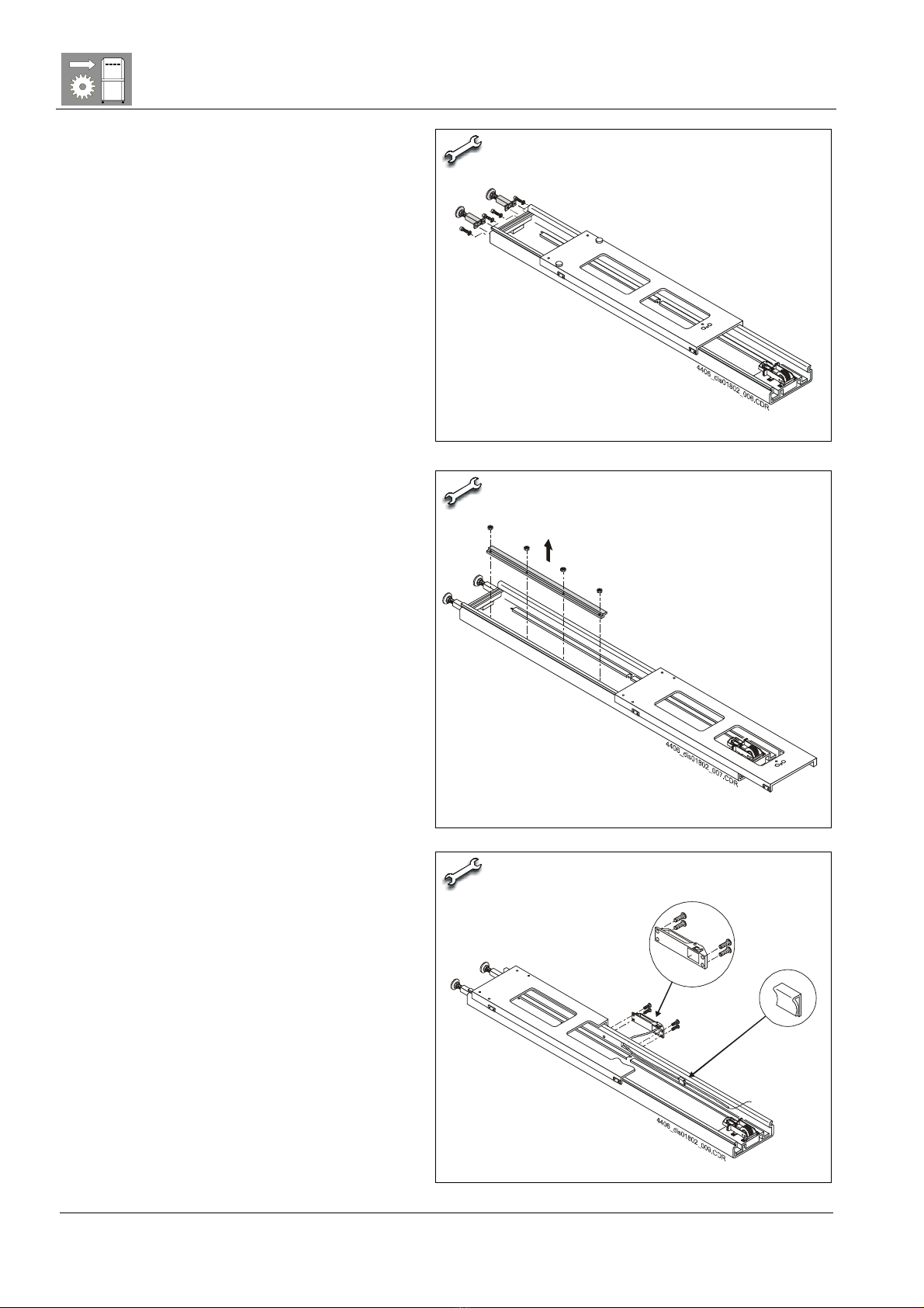
Cassette holder is only to be removed by a qualified service engineer.
The dismounting/removal of the cassette holder is not meant to be done by
the MTA, nurse and/or radiographer.
The device is only to be used with the Agfa Cassette holder.
Always use the device only for its intended use.
Always follow the instructions in the User Manual:
Take hold of cassette holder clamp
Take hold of release clamp
Pull release clamp & move cassette holder up/down
Push back release clamp
Let go of cassette holder clamp.
Always lock the Easylift device by dedicated locking mechanism before
dismounting/releasing the cassette holder (only by qualified service engineer!)
Always keep the dedicated locking mechanism in 'lock'-position as long as the
cassette holder is not attached.
Always attach the Cassette holder by qualified service engineer.
Always make sure that the cassette holder is fixed according to the mounting
instructions(see installation manual), before you use the system.
Always check if the release clamp is closed, before you unlock the system
Always check if no damage has occurred to the Easylift device and all of the
attached components before using the device.
Always notify a qualified service engineer in case of abnormal sounds,
movements and/or system blocking.
Never pull the release clamp when the cassette holder is not attached.
Never allow a non-authorized person to operate the system.
Never put a device or body part in the slot/slit of the Easylift device
Never try to move the cassette holder in another way as described in the user
manual.
Never try to lift up the cassette holder by yourself.
Never move the cassette holder without having at least one hand on the
cassette holder clamp.
Never try to open the device by yourself. The device is only to be opened by
service engineer.
Never open the device when the system is not locked.
Never lean on the device.
Never use the device as a support.
Never put additional weight to the device.
HOME

Accessories DD+DIS160.02E
Chapter 6 / 4 ADC System Components Edition 1, Revision 12
(Type 4406)
Safety instructions relevant for the field service engineer
See "Safety instructions relevant for the user" and additionally:
Wall attachment :
Always make sure that the hospital points out the methods and location of the
wall attachment.
This because the hospital responsible knows best where the utilities (water,
electricity, medical gasses, etc,...) are located. Additionally he knows best out
of which materials the walls are made of and which materials are best used to
fix devices of this weight to the wall. They also know about the presence of
wall lead protection. Therefore the hospital keeps responsibility of the method
& materials of wall-attachment of the Easylift device. Therefore it is best that a
hospital responsible person drills the holes into the wall.
Always use safety gloves and shoes during installation.
Always be aware of the fact that the counterweight has a weight of 32 kg.
Always install according to the instructions.
Always use the recommended tools when working on the device.
Always double check the connections of cassette holder, slide wagon, belt,
counterweight and braking cable
Always check the safety lock/unlock mechanism
Always confirm good operation after installation
Always inform the user about the user instructions
Always point out the use and function of the safety lock/unlock mechanism to
the user.
2 Certificates
The ADC Easylift is CE classified.
The ADC Easylift complies with the requirements of the
Directive 93/42 EEC, Medical Device Directive
The product is not an active device and imaginable risks have been evaluated
in a risk analysis accordingly
EN ISO 14971:2000 Medical Devices – application of risk management to
medical devices; no risks were found in the area of unacceptability
HOME

DD+DIS160.02E Accessories
Edition 1, Revision 12 ADC System Components Chapter 6 / 5
(Type 4406)
3 Scope of Delivery
The Full Leg/Full Spine Stand "ADC Easylift" consists of the following
assemblies:
•Framework with Sprocket Holder
•Counterweight
•Slide wagon
•Upper front cover
•Lower front cover
and the following single parts packed in small PE-bags:
•Handle, brake cable and sleeve
•Belt and belt connection to slide wagon
•Adjustable feet and holders
•Cassette holder mounting set
•Slide wagon locking screws
and documents:
•installation manual
•user manual
•assembly checklist (please store on a secure place as this document
may be needed for later reference in case of trouble with the
ADC Easylift)
4 Installation Planning
A safe installation of ADC Easylift requires two technicians
4.1 Installation Site
Upon defining the installation site please take into account:
•The ADC Easylift must be installed in front of a wall impervious to x-rays
•The floor covering must be solid enough to stand the weight of the ADC
Easylift (approx. 100 kg)
•The customer has to decide early enough if the ADC Easylift should be
operated from the left or right hand side.
•On the operator's side a minimum of 50 cm free space is needed to be
able to insert large format cassettes
•Make sure that you have at least 2 hours access to the x-ray room on the
day of installation
HOME

Accessories DD+DIS160.02E
Chapter 6 / 6 ADC System Components Edition 1, Revision 12
(Type 4406)
4.2 Fixation Requirements
The preparation of the wall fastening has to be done by the customer. They
have to take into account the material of the wall as well as the fixing material.
At the time of installation the preparation of the wall fastening must be finished
and the required fixation bolts must be on the spot.
For fixation requirements see Figure 1
(1) ADC Easylift
(2) Slide-wagon
(3) Cassette holder
(4) Two feet transfer the weight
of the complete device
(approx. 100 kg) to the floor.
(5) Two upper fixation bolts
(6) Two lower fixation bolts
1
3
max. load in this direction
150 kg per bolt
100 kg per bolt
Floor
Wall
4
5
6
2
4406_dis01802_001.cdr
Figure 1
HOME

DD+DIS160.02E Accessories
Edition 1, Revision 12 ADC System Components Chapter 6 / 7
(Type 4406)
4.3 Technical Data
Dimensions and Weights
Packing dimensions
(length x width x depth)
2375 mm x 595 mm x 385 mm
Dimensions ADC
Easylift mounted
(length x width x depth)
2300 mm x 390 mm x 135 mm
Dimensions slide-
wagon (length x width)
1300 mm x 390 mm
Weight with package ca. 75 kg
Weight without
package
ca. 70 kg
Weight slide wagon ca. 6 kg
Counterweight ca. 30.5 kg
Drill Holes
Top 2 holes at 2215 mm, 280 mm in between
Bottom 2 slotted holes between 255 and 265 mm, 280 mm
in between
Toothed belt
Dimensions
(length x width)
1540 mm x 30 mm
Breaking load 2500 N
The ADC Easylift does not need to be maintained during its expected life time
of seven years.
HOME

Accessories DD+DIS160.02E
Chapter 6 / 8 ADC System Components Edition 1, Revision 12
(Type 4406)
5 Unpacking ADC Easylift
Wear safety shoes and gloves while unpacking and installing ADC Easylift.
(1) Cut the fixing straps.
(risk of injury) and lift
off the wooden lid.
(2) Lift Easylift off the
case and unwrap it.
(3) Put it on firm ground
for further installation
steps
Figure 2
6 Installation Instructions
(1) Loosen 2 screws
connecting upper
and lower front
cover (1)
(2) Loosen 2 screws at
each side of lower
front cover (2).
(3) Draw off the lower
front cover while
lifting it a bit (3)
3mm allen key
Figure 3
HOME

DD+DIS160.02E Accessories
Edition 1, Revision 12 ADC System Components Chapter 6 / 9
(Type 4406)
(4) Loosen 3 screws at
each side of the
upper front cover (1)
(5) Draw off the lower
front cover while
lifting it a bit (3)
Do not bend
3mm allen key
Figure 4
(6) Unpack and check
the accessory kit
according to the
assembly checklist
3 cone pointed hex screws for fastening the brake-cable are attached with
tape to the sprocket holder
(7) Secure slide wagon
in lower locking
position by means of
2 slide wagon
locking screws.
Figure 5
HOME

Accessories DD+DIS160.02E
Chapter 6 / 10 ADC System Components Edition 1, Revision 12
(Type 4406)
(8) Fasten 2 adjustable
feet with 2 screws
each
5mm allen key
Figure 6
(9) Loosen 4 nuts at the
counterweight
bracket and remove
bracket
10mm offset box wrench or ratchet
Figure 7
(10) Fasten handle
with 4 allen screws
(11) Attach brake-
cable to cable clamp
(mounted on inner
side)
4mm allen key
Figure 8
HOME

DD+DIS160.02E Accessories
Edition 1, Revision 12 ADC System Components Chapter 6 / 11
(Type 4406)
(12) Pull the brake-
cable through the
opening in the
sprocket holder
(13) Check the correct
position of the
cable sleeve
(14) Fasten the brake-
cable with 2 cone
pointed allen
screws
(15) Cut off the
remaining cable
flat nose pliers, wire cutting pliers,
2mm allen key
Figure 9
(16) Lead belt through
sprocket (brake
has to be released)
Figure 10
(17) Fasten belt to slide
wagon 5mm allen key
Figure 11
HOME

Accessories DD+DIS160.02E
Chapter 6 / 12 ADC System Components Edition 1, Revision 12
(Type 4406)
(18) Put up the Easylift
and attach it with 4
bolts to the wall.
Use the bolts
provided by the
customer.
4406_dis01802_013.CDR
Figure 12
Risk of injury!
For the following installation steps the belt locking system must be blocked
4406_dis01802_021.CDR
Figure 13
HOME

DD+DIS160.02E Accessories
Edition 1, Revision 12 ADC System Components Chapter 6 / 13
(Type 4406)
(19) Loosen 4 locking
screws securing the
counterweight in the
box
(20) Take the
counterweight out of
the box
30,5 kg !
8mm socket wrench
Figure 14
(21) Secure slide wagon
in upper locking
position
(22) Put the
counterweight inside
the frame
(23) Fasten
counterweight
bracket again
10mm offset box wrench or ratchet
4406_dis01802_11.CDR
Figure 15
HOME

Accessories DD+DIS160.02E
Chapter 6 / 14 ADC System Components Edition 1, Revision 12
(Type 4406)
(24) Connect
counterweight with
belt by belt mounting
plate
6mm allen key
4406_dis01802_014.CDR
Figure 16
(25) Remove slide wagon
locking screws (1)
(26) Release belt locking
system (2)
(27) Move slide wagon
downward (3), (you
need a helping
hand)
4406_dis01802_015.CDR
Figure 17
HOME

DD+DIS160.02E Accessories
Edition 1, Revision 12 ADC System Components Chapter 6 / 15
(Type 4406)
(28) Mount upper front
cover with 3 allen
screws each side
3mm allen key
4406_dis01802_016.CDR
Figure 18
Risk of injury! Block belt locking system again (see below 1)
(29) Have your
assistance lift on the
slide wagon as far
as possible (2)
(30) Mount lower front
cover with 2 allen
screws each side
3mm allen key
4406_dis01802_017.CDR
Figure 19
HOME

Accessories DD+DIS160.02E
Chapter 6 / 16 ADC System Components Edition 1, Revision 12
(Type 4406)
(31) Mount the cassette
holder mounting
brackets at the
cassette holder (1)
(32) Attach the cassette
holder to the slide
wagon.
Take care that the
lugs have engaged
properly.
4406_dis01802_018.CDR
Figure 20
(33) Fasten the cassette
holder mounting
brackets to the slide
wagon (1)
(34) Release the belt
locking system.
5mm socket wrench
4406_dis01802_019.CDR
Figure 21
HOME

DD+DIS160.02E Accessories
Edition 1, Revision 12 ADC System Components Chapter 6 / 17
(Type 4406)
7 Finishing the Installation
(1) Check the ADC Easylift for
safe and proper function:
•reliable locking of both
locking systems of the
device
•smooth movement of slide
wagon/cassette holder
(2) Hand over the system to the
customer.
Point out especially
chapter 1, "Safety
Instructions" of this manual
The locking screws are needed for any repair/opening of the ADC Easylift.
Store them in a place where they can be found again.
HOME
Table of contents
Other AGFA Measuring Instrument manuals

AGFA
AGFA ADC Solo User manual

AGFA
AGFA ADC Compact Plus User manual

AGFA
AGFA CR 25.0 User manual

AGFA
AGFA CR 85-X User manual

AGFA
AGFA CR 85-X User manual

AGFA
AGFA 5522/100 User manual

AGFA
AGFA ADC Compact Plus User manual

AGFA
AGFA CR 30-X User manual

AGFA
AGFA PCR II Plus User manual

AGFA
AGFA DX-G User manual