AGFA CR 25.0 User manual

CR 25.0
User manual

22312A EN 20040909
❖
The device must only be operated according to its specifications and its intended
use. Any operation not corresponding to the specifications or intended use may
result in hazards, which in turn may lead to serious injuries or fatal accidents (for
example electric shocks). AGFA positively will not assume any liability in these
cases.
❖
The device must only be installed and put into operation under the specified
conditions.
For more information on Agfa products and Agfa HealthCare products, please visit www.agfa.com, your
Point of Knowledge.
© Agfa-Gevaert N.V. 2004.
No parts of this document may be reproduced, copied, adapted or transmitted in any form or by any means
without the written permission of Agfa-Gevaert N.V.
Agfa-Gevaert N.V. makes no warranties or representation, expressed or implied, with respect to the accu-
racy, completeness or usefulness of the information contained in this document and specifically disclaims
warranties of suitability for any particular purpose. Agfa-Gevaert N.V. shall under no circumstances be liable
for any damage arising from the use or inability to use any information, apparatus, method or process dis-
closed in this document.
Agfa-Gevaert N.V. reserves the right to make changes to this document without prior notice.
Agfa-Gevaert N.V., Septestraat 27, B-2640 Mortsel, Belgium.
CR 25.0 is a trademark of Agfa-Gevaert N.V., Belgium.
Agfa and the Agfa-Rhombus are trademarks of Agfa-Gevaert AG, Germany.

3
2312A EN 20040909
Table of contents
Chapter 1: Introducing the CR 25.0 ........................................................................ 5
CR 25.0 intended use............................................................................................. 6
CR 25.0 features..................................................................................................... 7
Safety precautions .................................................................................................. 8
Safety compliance................................................................................................. 12
Operating modes .................................................................................................. 13
Configurations....................................................................................................... 14
The user interface................................................................................................. 16
Switching on the CR 25.0...................................................................................... 24
Switching off the CR 25.0...................................................................................... 26
Chapter 2: Basic operation (‘Operator mode’)..................................................... 27
Workflow............................................................................................................... 28
Reading an image plate........................................................................................ 29
Reading an emergency image plate...................................................................... 35
Re-erasing an image plate.................................................................................... 42
Reading the identification data of a cassette (Dedicated configuration only)......... 46
Changing the image plate type (Dedicated configuration only)............................. 48
Chapter 3: Advanced operation (‘Key-operator mode’)...................................... 51
Survey of advanced functions (‘Key-operator mode’)............................................ 52
Checking the image quality................................................................................... 53
Troubleshooting checklist...................................................................................... 54
Appendix A: Equipment information sheet.......................................................... 59
Appendix B: ADC Compact cassette.................................................................... 63
Appendix C: Remarks for HF-emission and immunity ....................................... 73

42312A EN 20040909

62312A EN 20040909
CR 25.0 intended use
This device must only be used to scan exposed X-ray cassettes, containing an
erasable image plate (IP). This device is part of a system, consisting of
X-ray cassettes with erasable phosphor image plates, an identification station for
the cassettes and a workstation where the resulting digital image information is
further processed and routed. This device is intended to be operated in a
radiological environment by qualified staff.

7
2312A EN 20040909
CR 25.0 features
The CR 25.0 is a Digitizer for image plates retaining latent X-ray images. It has
been developed by Agfa.
■The CR 25.0 accepts one cassette containing one image plate at a time. The
CR 25.0:
•takes the cassette containing the image plate from the cassette slot;
•removes the image plate from the cassette;
•scans the image plate;
•converts the information of the latent image to digital data;
•transmits the image data to the preview station;
•erases the image plate and re-inserts it into the cassette;
•gives the cassette ID data the status ‘erased’;
•returns the cassette;
•transmits the digital image data to an image processing station (‘destination’).
■The CR 25.0 allows assigning the status ‘emergency’ to an image.
The Digitizer gives an image priority to be sent to the image processing station if the
“Emergency key” was pressed before inserting an unidentified cassette.
■The CR 25.0 allows re-erasing an image plate before re-using it. In specific
cases, this is necessary to prevent ghost images caused by previous exposures
or stray radiation from interfering with the image of interest.
■If the CR 25.0 is dedicated to one ID Station, additional features are available:
•quickly identifying cassettes without the need for an ID Tablet;
•reading the identification data of a cassette;
•initializing a cassette, i.e. changing the image plate type.

82312A EN 20040909
Safety precautions
General safety instructions
•For software and other technical platforms, and/or if valid in combination with any
consumable, which constitute, after installation, a system for the interpretation of
medical image data by trained and qualified professionals: it is the user's
responsibility to ensure that image quality, display quality, environmental lighting and
other possible distractions are consistent with the clinical application.
•Make sure that the CR 25.0 is constantly monitored in order to avoid inappropriate
handling, especially by children.
•Only trained service personnel must make repairs. Only authorized service personnel
must make changes to the CR 25.0.
•If there is any visible damage to the machine casing, do not start nor use the
CR 25.0.
•If you want to connect the CR 25.0 with other devices, components or assemblies and
if the technical data do not allow determining whether the combination with these
devices, components or assemblies involves hazards, you must consult the
respective manufacturers to avoid danger for operating personnel or the environment.
•Do not override or disconnect the integrated safety features.
•As is the case for all technical devices, the CR 25.0 must be operated, cared for and
serviced correctly.
•If you don’t operate the CR 25.0 correctly or if you don’t have it serviced correctly,
Agfa-Gevaert is not liable for resulting disturbances, damages or injuries.
•When installing the CR 25.0, care must be taken to ensure that there is either a mains
plug or an all-cable disconnecting device in the internal installation fitted near the
CR 25.0 and that it is easily accessible.
•If you notice conspicuous noise or smoke, disconnect the CR 25.0 immediately.
•Check that the mains voltage is within the specified range of the self adapting power
supply of the machine.
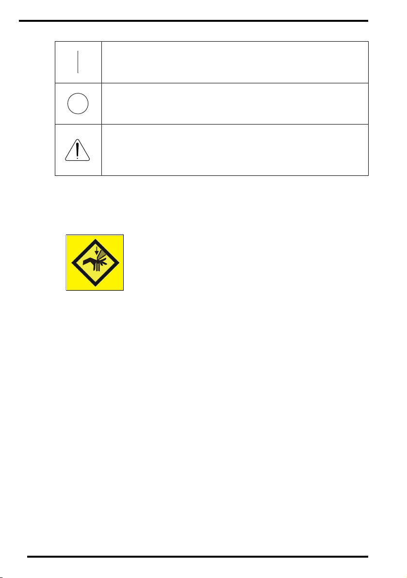
Markings and labels
Always take into account the markings and labels provided on the inside and out-
side of the machine. A brief overview of these markings and labels and their
meaning is given below.

9
2312A EN 20040909
Safety warning, indicating that the CR 25.0 manuals should be
consulted before making any connections to other equipment. The
use of accessory equipment not complying with the equivalent
safety requirements of this Digitizer may lead to a reduced level of
safety of the resulting system. Consideration relating to the choice
of accessory equipment shall include:
• Use of the accessory equipment in the patient vicinity,
• Evidence that the safety certification of the accessory equipment
has been performed in accordance with the appropriate IEC 601-
1 and IEC 601-1-1 harmonized national standard.
In addition all configurations must comply with the medical
electrical systems standard IEC 601-1-1. The party that makes the
connections acts as system configurator and is responsible for
complying with the systems standard.
If required contact your local service organization.
In order to reduce the risk of electric shock, do not remove any
covers.
Caution hot:
Keep hands clear from the erasure unit.
Type B equipment:
Indicates that the CR 25.0 complies with the limits for type B
equipment.
Supplementary protective earth connector:
Provides a connection between the CR 25.0 and the potential
equalization busbar of the electrical system as found in medical
environments. This plug should never be unplugged before the
power is turned off and the power plug has been removed.
Intergrounding connector:
Provides a connection between the Digitizer and other equipment
which might exhibit minor ground potential differences. These
differences may degrade the quality of communication between
different equipment. Never remove connections to this terminal.
Protective earth (ground):
Provides a connection between the Digitizer and the protective
earth of the mains. Do not remove this connection, because this
will have a negative influence on the leakage current.

10 2312A EN 20040909
• You can hurt your fingers if they are caught between the ADC Cassette and the
edge of the input slot. Insert the cassette in the input buffer as described in
‘Reading an image plate’ on page 29. At all times, keep your fingers clear of the
input slot. As soon as the cassette enters the CR 25.0, release it.
System configuration responsibility
Accessory equipment connected to the analog and digital interfaces must be
certified according to the respective IEC standards (e.g. IEC 950 for data
processing equipment and IEC 601-1 for medical equipment). Furthermore all
configurations shall comply with the valid version of the system standard IEC 601-
1-1. Everybody who connects additional equipment to the signal input part or
signal output part configures a medical system, and is therefore responsible that
the system complies with the requirements of the valid version of the system
standard IEC 601-1-1. If in doubt, consult your local service organization.
Power On
Power Off
Note that the power cord has to be disconnected from the wall
outlet in order to disconnect the unit entirely from the mains.
Precautions for use in USA only:
Make sure that the circuit is single-phase center-tapped, if the
Digitizer is connected to a 240 V/60 Hz source instead of a 120 V/
60 Hz source.

11
2312A EN 20040909
Safety instructions for laser products
The CR 25.0 is a Class 1 Laser Product. It uses a 2x50 mW laser diode,
classification class IIIb.
Under normal operating conditions - when both doors are closed - there can be no
laser radiation outside the CR 25.0. It is nonetheless imperative that the local
radiation safety regulations regarding the protection of staff against scattered
radiation are complied with, if the CR 25.0 is located in the immediate vicinity of an
X-ray room.
Open the front left and right door only to solve cassette or image plate jams. When
you open either of the doors, the power supply of all critical components is
switched off automatically as a precaution.
Observe the Caution instructions on the Optical module label:
User interventions other than those described in this manual can be
hazardous with regard to laser radiation.
CAUTION!
CLASS 3B LASER RADIATION:
WHEN OPEN AVOID DIRECT
EXPOSURE TO THE BEAM!
CUIDADO!
RAYO LASER CLASE 3B:
EVITAR LA EXPOSICIÓN AL HAZ
CUANDO LA TAPA ESTÁ ABIERTA.
VORSICHT !
LASERSTRAHLUNG KLASSE 3B:
WENN ABDECKUNG GEÖFFNET
NICHT DEM STRAHL AUSSETZEN!
ATTENTION!
FAISCEAU LASER CLASSE 3B:
QUAND CAPOT OUVERT ÉVITER
DE S´EXPOSER AU RAYÓN!

12 2312A EN 20040909
Safety compliance
Certificates
The CR 25.0 complies with:
•the general safety regulations:
EN 60601-1 :1990 / A1:1993, A2:1995, A13:1996,
EN 60601-1-2 :2001,
IEC 601-1 :1988/A1 :1991, A2 :1995,
IEC 601-1-1 / EN 60601-1-1,
UL 60601-1:2003,
CAN / CSA C22.2 No.601.1-M90.
•the laser safety regulations:
EN 60825-1: 1994 / A1:2002, A2:2001,
DHHS/FDA 21 CFR, Parts 1040.10 and 1040.11,
ANSI Z 136-1980.
•EN ISO 14971:2000,
EN 1041:1998,
EN 980:1996/A1.
❖
The Digitizer is in compliance with the EG regulation 93/42/EEC Directive
(Medical Device).
Radio Interference Suppression
It is hereby certified that the Digitizer has interference suppression according to
the EN 55011 Class B as well as the FCC Rules CR47 Part 15 Class B (North-
America).
Short-range devices
EN 300 330-2 V1.1.1
EN 301 489-03 V1.2.1
For USA only:
This equipment has been tested and found to comply with the limits for a
Class B digital device, pursuant to part 15 of the FCC Rules. These limits are
designed to provide reasonable protection against harmful interference in a
residential installation. This equipment generates, uses and can radiate radio
frequency energy and, if not installed and used in accordance with the
instructions, may cause harmful interference to radio communications. In
case the equipment causes harmful interference to other devices, see the
User manual for help.

13
2312A EN 20040909
Operating modes
The CR 25.0 can be operated in three modes: operator mode, key-operator mode,
and service mode.
Operator mode
The operator mode groups all basic functions which are aimed at radiographers:
•Reading an image plate;
•Reading an emergency image plate;
•Re-erasing an image plate;
•Reading the identification data of a cassette (Dedicated configuration only);
•Changing the image plate type (Dedicated configuration only).
All functions of the operator mode are described in Chapter 2, ‘Basic operation
(‘Operator mode’)’.
Key-operator mode
The key-operator mode groups advanced functions which are aimed at
technicians.
The key-operator mode can be accessed via the Key-operator key on the keypad
and is menu-driven. The key-operator functions are described in Chapter 3,
‘Advanced operation (‘Key-operator mode’)’.
Service mode
The service mode functions are reserved for trained service personnel. They are
password protected.

14 2312A EN 20040909
Configurations
The CR 25.0 can be used in two configurations: either one or more ID Stations
serve a range of Digitizers, or one ID Station is dedicated to one Digitizer. For the
ID Station a CR User Station with included ID Tablet can be used as well as a
stand-alone ID Tablet. The ID Software installed on the PC is slightly different
depending on the configuration. For more information, contact your local service
organization.
Interchangeable configuration
One or more ID Stations can serve a range of Digitizers, provided that each ID
Station has an ID Tablet. There is no physical link required between the ID Station
and the Digitizer.
In this configuration, a cassette can be identified via any of the ID Stations and
subsequently be scanned using any of the Digitizers. The patient demographic
data and examination data are entered via the ID Viewer Software and stored in
the memory chip of the ADC cassette via the ID Tablet. As a result the
identification data are linked to the cassette and any Digitizer can be used to scan
the cassette.
The interchangeable configuration allows the flexible use of several Digitizers and
ID Stations depending on the workload.
CR 25.0
Interchangeable configuration
ID Station with
ID Tablet

15
2312A EN 20040909
Dedicated configuration
If one ID Station is dedicated to one Digitizer, cassettes can be identified without
using an ID Tablet. The identification data are transmitted from the ID Station to
the Digitizer via the network.
The dedicated configuration reduces the time required for identifying and scanning
a cassette because both actions can be performed simultaneously.
❖
In the dedicated configuration, you can still use the CR 25.0 to digitize
cassettes which have been identified on an ID Station or a CR User Station.
CR 25.0
ID Station without ID Tablet
Dedicated configuration

16 2312A EN 20040909
The user interface
The CR 25.0 has three operation modes:
•the operator mode for basic operation;
•the key-operator mode for advanced operation;
•the service mode reserved for trained service personnel.
The functions of the operator mode are described in Chapter 2, ‘Basic operation
(‘Operator mode’)’. An overview of the functions of the key-operator mode is given
in ‘Survey of advanced functions (‘Key-operator mode’)’ on page 52. For detailed
information on the key-operator mode, refer to the CR 25.0 Reference manual.
The CR 25.0 interfaces with the user via:
•a keypad and a display;
•a status indicator;
•emergency buttons;
•audio signals.
3
12
1Status indicator
2Emergency buttons
3Keypad and display

17
2312A EN 20040909
The keypad
The CR 25.0 keypad features the following keys:
Emergency
key
To give an image priority to be sent to the image
processing station if other images are already waiting
in the image queue.
This key can only be used for unidentified cassettes.
Erase key
To erase images without digitizing them.
This must be done if:
• an image plate has not been used for more than
3 days;
• an image plate has been exposed to an
exceptionally high X-ray dose.
Key-
operator
key
To access advanced functions (‘key-operator
functions’).
Service key To access service-level functions.
Reserved for trained service personnel.
Escape key To quit the current function or exit a menu without
saving modifications.
Confirm key
In key-operator mode:
• to select a menu.
• to accept an entry in a menu and go back to
operator mode.

18 2312A EN 20040909
Up key • To move the cursor to the previous entry field.
• To scroll upwards.
• To increment the number in a numeric entry field.
Down key • To move the cursor to the next entry field.
• To scroll downwards.
• To decrement the number in a numeric entry field.
Left key
• To scroll backwards through multiple choices within
a field.
• To move the entry position in a numerical entry field
from right to left.
• To toggle between values in a field.
Right key
• To scroll forwards through multiple choices within a
field.
• To move the entry position in a numerical entry field
from left to right.
• To toggle between values in a field.

19
2312A EN 20040909
The display
The CR 25.0 control panel has a backlit LCD display with 8 lines of
40 characters each. Its lay-out depends on the operating mode.
◆In operator mode, the display has dedicated areas for specific information:
1Set-up of image processing station:
• [blank]: Default image processing station selected.
• Off line: Transmission to all image processing stations disabled.
• [process.station] not ready: Image processing station not available.
• [process.station] rerouted: Images rerouted to other image processing
station (ask the Agfa service technician if your system supports this
configuration).
2Type of message
3Extra comment or action to take
4System status:
• READY: The CR 25.0 is ready for operation.
• BUSY: The CR 25.0 is treating an image plate.
• ERROR: An error has occurred. Refer to ‘Troubleshooting checklist’ on
page 54.
• LOCKED: id.
• WARNING: id.
3
Set-up STATUS
OPERATION MODE
1ST MESSAGE
2nd Message
Patient_Last_Name Sub_Exam
Station Name ERROR
5
6
8.1
8.2
8.3
124
7

20 2312A EN 20040909
The operator main screen is:
When the CR 25.0 is treating an image plate, it displays the following screen:
5Operation mode:
• [blank]: Normal operation mode.
• EMERGENCY: Emergency function for image plates with ID data.
• EMERGENCY BUTTON: Emergency function for image plates without
ID data.
• ERASURE: Re-erasure function.
• DIRECT ID: Operation in dedicated configuration.
6Error status: service code (SERVICE XXXXX) or error code (CODE XXXXX)
7Station name of the CR 25.0
Identifier of image plate being treated:
8.1
8.2
8.3
After image ID data is read;
During scanning of image plate and transmittal of image data;
During transmittal of image data to image processing station.
READY
CR 25.0
BUSY
Miller Chest AP
Table of contents
Other AGFA Measuring Instrument manuals

AGFA
AGFA CR 30-X User manual

AGFA
AGFA ADC Solo User manual

AGFA
AGFA ADC Compact Plus User manual

AGFA
AGFA CR 10-X User manual

AGFA
AGFA CR 75.0 User manual

AGFA
AGFA CR 85-X User manual

AGFA
AGFA ADC Compact Plus User manual

AGFA
AGFA CR 85-X User manual

AGFA
AGFA 4406/027 User manual

AGFA
AGFA PCR II Plus User manual