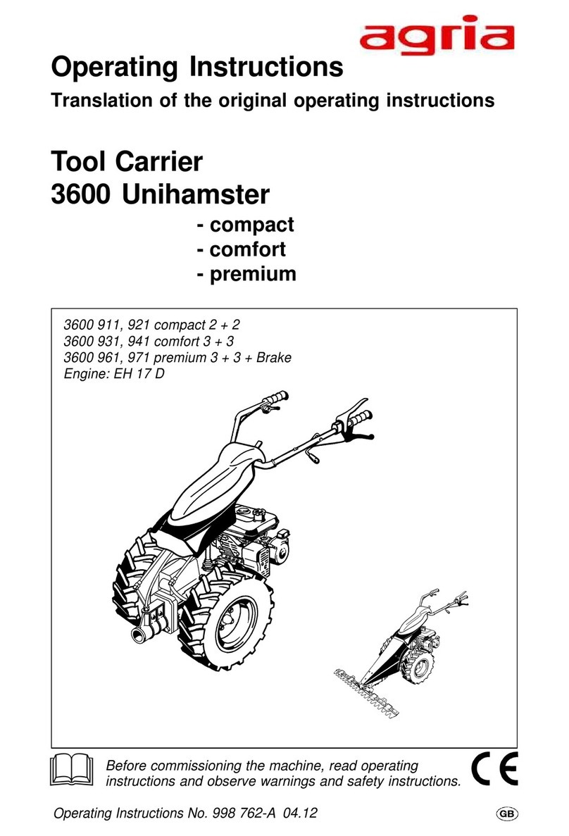
Agria 6000 User manual

OperatingInstructionsNo.998720 11.98
Before commissioning the machine, read operating instructions
and observe warnings and safety instructions.
3308, 3307
Operating Instructions
for agria
®
Power Hoe Type 6000
&
Quality that's your
pleasure!
Horticultural MachineryHorticultural Machinery
Horticultural Machinery

2 PowerHoe 6000 Edition11.98
Symbols, Name Plate
Please complete:
MachineTypeNo.: .........................
ID/MachineNo.:
......................................................
EngineType: ..................................
EngineNo.: ....................................
Dateof Purchase: ..........................
Forname plate,referto p5/fig.B/26.
For engine type and number, refer to
p5/itemno.27.
Please state these data when ordering
spareparts toavoid wrongdeliveries.
Only use original agria spare parts!
Specifications, figures and dimensions
statedintheseinstructions arenotbind-
ing.Noclaimscanbederivedfromthem.
We reserve the right for improvements
withoutchanging theseinstructions.
This delivery comprises:
l
Operatinginstructions
l
Powerhoe
–basic machine
–steering handle
l
Toolkit
Symbols
Warning– Danger
Importantinformation
Choke
Fuel
Oil
Hoeing/tillingdrive
Visual check
Open(unlocked)
Closed(locked)

Edition11.98 Power Hoe6000 3
Designation of Parts
Figure A
Figure B
27

4 PowerHoe 6000 Edition11.98
Designation of Parts
Figures A and B
1 Steeringhandle
2 Tensioninglever forsteeringhandle sideadjustment
3 Spark plug / spark plug connector
4 Exhaust
5 Fueltank lid
6 Fueltank
7 Oilimmersed airfilter
8 Manualgearbox –oilfilling controlplug
9 Tubes forattachmentof guards
10 Hoeingdrive
11 Hoeingshaft
12 Hoeing drive– lubricantcontrol /filler plug
13 Steeringhandle height-adjustmenthex headbolt
14 Starterhandle
15 Carburetor
16 Coolingair-grille
17 Leg
18 Hitch
19 Hoeingleg
20 Hoeingshare
21 Clutch /chain-drive housingcover
22 Coverattachment nut
23 Manualgearbox –oildrain plug
24 Chaintensioning screw
25 Fueltap
26 Nameplate/I.D.no.
27 Enginetype plate

Edition11.98 Power Hoe6000 5
Index
Amount of Delivery ..........................3
Recommendations
Lubricants,Anti-CorrosiveAgents ......4
Fuel ....................................................4
MaintenanceandRepair.....................4
Designation of Parts ..................5,35
Assembly Instructions .....................7
1. Safety Instructions .................8–12
2.Specifications
Dimensions ......................................13
PowerHoe........................................13
NoiseLevel.......................................13
Engine ..............................................14
Operationon Slopes.........................14
3. Devices and
Operating Elements
Engine ..............................................15
DeadStop Lever...............................16
Clutch ...............................................16
Gearbox ...........................................17
Hitch .................................................17
SteeringHandle................................18
Drive-Wheels....................................18
Wheel-Weights .................................19
Frontsupport wheel..........................20
HoeingTools .....................................20
HoeingGuards .................................22
4. Commissioning and Operation
Commissioningthe Machine ............23
Startingthe Engine ...........................24
Switchingoff theEngine ...................25
Hoeing ..............................................26
5.Maintenance
Engine ..............................................27
ManualGearbox ...............................29
HoeingDrive ....................................30
Adjustmentson HandLevers ...........30
DeadStop ........................................31
GeneralMaintenance .......................31
Cleaning ...........................................31
Storage.............................................32
Lubricants,Varnishes,
Wear Parts.......................................33
6.Troubleshooting ....................34–35
7. Inspection and
Maintenance Chart .........................36
Electric Wiring Diagram .................37
Conformity Declaration ..................39
Note fold-out pages!
Fig. A + B...........................................5
Fig. C ...............................................38

6 PowerHoe 6000 Edition11.98
Recommendations
Lubricants and
Anti-Corrosive Agents:
Use the lubricants specified for engine
andgearbox (see“Specifications”).
We recommend using Bio-lubricating
oil orBio-lubricating grease for“open”
lubricationpointsornipples(asspecified
inthe operatinginstructions).
Werecommend usingBio-slushing oil
to preserve machines and attachments
(donotapplyonpaintedcovers).Youcan
brush or spray the oil.
Anti-corrosive agents are environmen-
tallyfriendly anddegradefast.
Using ecologically safe Bio-lubricants
andBio-anti-corrosives,youcontributeto
environmental protection and to the
wellbeingofhumans,animalsandplants.
Fuel
The 2-stroke-engine runs on commer-
cialoil-petrol mixtures (forthespecified
stoichiometric ratio refer to “Specifica-
tions”). Unleaded regular and
supergrade petrol as well as leaded
supergrade petrol can be used for the
fuel mixture. However, only use self-
mixing special 2-stroke-engine oil (refer
to“Specifications”, p15).
If,for environmentalreasons, youuse
unleadedpetrol, makesurethe fuelis
drained completely when shutting
downtheengineformorethan30days.
This is to prevent resin residue from
depositing in the caburetor, fuel filter,
andtank.Oraddafuelstabilizingliquid
tothe fuel.
When storing the machine at the end
of the season, also drain leaded fuel
completelyoradd afuel stabilizingliq-
uid.
For further instructions see “Engine
Preservation”.
Maintenance and
Repair:
The trained mechanics of your agria
workshopexpertlycarryout anymain-
tenanceand repairwork.
You shouldonly carryoutmajor main-
tenanceworkandrepairsonyourown,
ifyouhavethepropertoolsandknowl-
edge of machines and internal com-
bustionengines.
Do not hammer against the flywheel
with a hard object or metal tools as it
might crack and shatter in operation,
causinginjuriesanddamage.Onlyuse
suitabletools topull offthe flywheel.

Edition11.98 Power Hoe6000 7
Unpacking and Assembly
1 Steeringhandle
2 Tommynut
3 Lockingplate onsteeringhandle
4 Lockingplate onjoint
5 Hexhead bolt
l
Openthe topof thecardboard box.
l
Removetommynut(2).Takehexhead
bolt(5).
l
Placethesteering handle(1)ontothe
locking plate (4) and hold it in place.
Ensure no Bowden cables or electric
cables are twisted or squeezed as you
aredoing this.
l
Insert the hex head bolt (5) from the
bottomthroughthe jointandthesteering
handle.
l
Attach the tommy nut (2).
l
Movethesteeringhandleuntilitsteeth
engage with the locking plate teeth.
Tightenthetommynut.
l
Attach the Bowden cables and elec-
triclineto thehandlebars usingtheclips.
l
Steering handle removal is in re-
verseorder.
l
To start up, carry out all steps de-
scribedon page23.

8 PowerHoe 6000 Edition11.98
1. Safety Instructions
Before starting the engine, read the op-
eratinginstructions andnote:
Warning
Thissymbolmarksall paragraphsaffect-
ing your safety. Pass all safety instruc-
tionsto otherusers andoperators.
Due Use
The power hoe has exclusively been
designedforallcommonapplicationsand
tasksinagriculture, forestry,horticulture,
grassand parkmaintenance (dueuse).
Any other type of use is considered un-
due.Themanufacturerisnotliableforany
damages resulting from undue use, for
which the risk lies with the user alone.
Dueuseincludescompliancewithmanu-
facturer’sinstructionsonoperation,main-
tenanceand repair.
Anyunauthorized changesto thepower
hoerendermanufacturerliabilitynull and
void.
General Instructions
on Safety and
Accident Prevention
Basic Rule:
The standard accident prevention regu-
lationsmust beadhered to,aswell asall
other generally accepted rules govern-
ing operational safety, occupational
healthand roadtrafficregulations.
Fortravellingonpublicroads, thecurrent
trafficcode applies.
Check the power hoe for road and op-
erational safety each time you take up
operation.
Onlypersonsfamiliarwith thepowerhoe
and instructed on the hazards of opera-
tion are allowed to use, maintain and
repairthe machine.
Teenagers of 16 years or younger may
notoperate thepowerhoe!
Only work in good light and visibility.
Operator’sclothesshould fittight.Avoid
wearingloose fittingclothes. Wear solid
shoes.
Note the warning and instruction signs
on the power hoe for safe operation.
Complianceis foryour ownsafety.
When transporting the power hoe on
vehiclesortrailers outsidethearea tobe
cultivated, ensure that the engine is
turnedoff.
Carefulwithrotatingtools–keepatasafe
distance!

Edition11.98 Power Hoe6000 9
1. Safety Instructions
Bewareofcoastingtools.Beforeyoustart
anymaintenance orrepair onthem,wait
untiltoolshavecometoa completestop.
Foreignpowered partsshearand crush!
Riding on the attachment during opera-
tionis notpermitted.
Attachments and their weight affect the
driving, steering, braking, and tip-over
characteristicsof thepower hoe.There-
fore, ensure steering and braking func-
tions are sufficient. Match operating
speedto conditions.
Do not change governor settings. High
enginespeedincreasesriskofaccidents.
Working Area and
Dangerous Area
Theuser isliableto thirdpartiesworking
withinthe powerhoe’sworking range.
Staying in the hazardous area of the
powerhoe isnot permitted.
Checktheimmediatesurroundingsofthe
powerhoe beforeyou startit. Watch out
forchildren andanimals.
Beforeyoustartwork,cleartheareafrom
any foreign object. During operation,
alwayswatch outfor furtherobjects and
removethem intime.
Foroperation inenclosedareas, ensure
that a safety distance is kept to enclo-
suresto preventdamage totools.
Operation and
Safety Devices
Before you start operation
Become familiar with the devices and
operating elements and their functions.
Above all, learn how to turn off the en-
gine quickly and safely in case of an
emergency.
Ensure that all protective devices are
mounted and positioned to provide pro-
tection.
Withnoattachmentmounted,make sure
PTO-shaftiscovered withtheprotective
cap.
Starting the engine
Donotstart engineinclosedrooms. The
carbon monoxide contained in the ex-
haust fume is extremely toxic when in-
haled.
Before you start the engine set all oper-
ating elements to neutral or idling posi-
tion.
Forstartingtheengine,donotstepinfront
ofthe powerhoe andtheattachment.
Operation
Neverleavetheoperator’spositionatthe
steering handle while power hoe is at
work.
Neveradjustthe steeringhandlesduring
work– danger!

10 PowerHoe 6000 Edition11.98
1. Safety Instructions
For any operation do not leave the op-
erator’spositionas definedby thesteer-
inghandle, especiallynotwhen youturn
themachine.
Riding on the attachment during opera-
tion or in transport is not permitted.
Ifcloggingoccurs inthe attachment,turn
off the engine and clean the attachment
withan appropriatetool.
Incaseof damagetothe powerhoe orto
theattachment, immediatelyturn offthe
engineand haveitrepaired.
Ifsteeringcausesproblems,immediately
bring the power hoe to a halt and turn it
off.Havethemalfunctionremovedwithout
delay.
Toprevent thepowerhoe fromsliding on
slopesmakesureitissecuredbyanother
personusingabarorarope.This person
mustbelocated atahigherposition than
the vehicle at a safe distance from the
attachmentat work.
If possible, always work horizontally to
theslope.
End of Operation
Never leave the power hoe unattended
withthe enginerunning.
Beforeyou leavethe powerhoe,turn off
theengine. Thenclose fueltap.
Securepower hoeagainstunauthorized
use– removespark plugconnector.
Attachments
Onlymountattachments withtheengine
andattachment driveswitchedoff.
Always use appropriate tools and wear
gloveswhen changingattachments and
partsthereof.
For mounting and dismounting attach-
mentsbringsupport legintoproperposi-
tionand ensurestability.
Secure power hoe and attachments
againstrolling off(wheelwedge).
Bewareofinjuries whencouplingattach-
ments.Proceed withextreme caution.
Mountattachmentsasspecifiedandonly
coupleat specifiedpoints.
Secure power hoe and attachment
against unauthorized use and rolling off
when you leave the machine. If neces-
sary,install transportorsecurity devices
andsecure.
Hoeing Attachment
Adjustprotective hoodof hoeingattach-
ment so that only those parts of tools
whichpenetratethe soilare notcovered.
When hoeing, make sure hoeing skid is
adjustedproperly.

Edition11.98 Power Hoe6000 11
1. Safety Instructions
Maintenance
Never carry out any maintenance or
cleaningwith theenginerunning.
In addition, always remove spark plug
connectorbeforeyouworkontheengine.
Check regularly and, if necessary, re-
place all protecting devices and tools
subjectto wearand tear.
Replacedamaged cuttingtools.
Always wear safety gloves and use
proper tools when exchanging cutting
tools.
Do not carry out repairs like welding,
grinding, drilling, etc. on structural and
safety-relevant parts (e.g. coupling de-
vices)!
Keep power hoe and attachment clean
to avoid risk of fire.
Checknutsandscrews regularlyfor tight
fitand re-tighten,if necessary.
Ensure that you re-install all safety and
protectivedevicesandadjust themprop-
erlyafter maintenanceandcleaning.
Only use original agria spare parts. All
other commercial spare parts must cor-
respondto qualityand technicalrequire-
mentsspecified byagria.
Storage
Itisnot allowedtostorethe powerhoe in
roomswith openheating.
Never park the power hoe in closed
roomswith fuelleftin tank.Fuelvapours
arehazardous.
Engine, Fuel, and Oil
Neverlettheenginerunin closedrooms.
Extremedanger ofintoxication!
Careful when dealing with fuel. Great
danger of fire! Never refill fuel close to
open fire, inflammable sparks or hot
engine parts. Do not refill fuel in closed
rooms.Do notsmokewhen refilling!
Refill only with the engine switched off
andcooled down.
Do not spill any fuel, use a proper filling
device.
In case of fuel-spillage, push the power
hoe away from the spillage before you
startthe engine.
Make sure fuel is of specified quality.
Storefuel inapproved cansonly.
Storeanti-corrosive agentsand stabiliz-
ingliquidsoutofreach ofchildren.Ifsick-
nessand vomitingoccur, seeadoctor.If
fuel has contacted eyes, rinse them
thoroughly,avoid inhalingof vapours.
Readandobserveenclosedinstructions.

12 PowerHoe 6000 Edition11.98
1. Safety Instructions
Beforeyoudisposeofopenedandseem-
ingly empty pressurised tins make sure
they are completely empty. Empty them
in ventilated places safe from spark
formationorflames.Ifnecessary,dispose
oftins inhazardous wastedeposits.
Careful when draining hot oil, danger of
burns.
Makesureoil usedis ofspecified quality.
Storageis inapproved cansonly.
Dispose of oil, greases, and filters
seperatelyand properly.
Tyres and
Tyre Air Pressure
Whenworkingontyres,makesurepower
hoe is parked properly and secured
againstrolling off.
Any repairs are to be carried out by
trained mechanics only and with the
appropriatetools.
Regularlychecktyreairpressure.Exces-
sive air pressure may cause bursts.
Use appropriate tyre air pressure when
mountingfrontweight.
Re-tighten attachment bolts of drive-
wheels or check tightness when doing
maintenancework.
Electrical System and
Battery
Persons having a pacemaker may not
touch live parts of the ignition system
whenthe engineis running.
Explanation of
Warning Signs
Before any cleaning, maintenance, and
repairworkswitch offtheengine andpull
sparkplug connector.
With engine running, keep at a safe dis-
tancefrom hoeingtools.
Do not work without protective covers
mounted.Beforestartingtheengine,bring
coversinto properposition.

Edition11.98 Power Hoe6000 13
2. Specifications
Machine Dimensions:
a..........................................310 mm
b..........................................620 mm
c........................................1000mm
d..........................................890 mm
h............................. ca.700–950mm
l.........................................1250 mm
A .................................100–650mm
(depending on type of tilling attach-
ment)
Manufacturedaccordingto
CEN/GSsafety standards:
e.......................................> 150 mm
f ............... > 500 mm at h = 800 mm
Accessories:
Hoe34–100 cm
Frontsupport wheel...............0189 421
Ridger....................................3452021
Wheelhubs ...........................6019511
Drive-wheels .........................0190 111
Wheelweights .......................0421011
Hitch ......................................4040021
Conventionalplough ..............3441021
Quarter-turnplough ...............3444021
Potatoraisingplough .............3443021
Springtine cultivator ..............3472 021
Combinedrotary harrow ........3473 021
Model designation ..................... 6000
Gearbox ........3-speedmanualgearbox
and1 rollerchain driving
hoeingshaft/wheel shaft
Oil filling quantities
Gearboxin engineblock
TransmissionoilBPTFJD-GL4 .....0.30l
inchain drive top
Transmissionsemi-fluidgrease .... 350g
BPEnergrease LS-EP00
inhoeing drive
Transmissionsemi-fluidgrease .... 350g
BPEnergrease LS-EP00
Hoeing width:........ Dependingontype
of hoeing accessory
Tyres: ....................... 5.0-10(field tyre)
Tyrepressure: ........................... 1.2bar
Noiselevels:
In accordance with German 3rd Ordi-
nanceon machine-safetylaw:
Noiselevel atoperator’sear ......90dBA
Soundlevel ...........................101.5dBA
(inaccordance withregulations of
GermanAgriculturalAssociation)
Clutch: ............................Oil immersed
multi-plateclutch
Weight: .......................... approx.56kg.
Speed steps
Gear Hoeing tool
[rpm]
Ground speed
[km/h]
with 5.0-10
tyres fitted
1 66 6
2 98 9
3 172 15.7

14 PowerHoe 6000 Edition11.98
2. Specifications
Engine
Manufacturer:..............................agria
Type: .................................... 66/6 or 1*
Version: ........................ Fan-air-cooled
1-cylinder-2-strokeengine (petrol)
Lubrication:.............Petroil lubrication;
stoichiometricratio 1:30
Bore: ........................................ 56mm
Stroke: ..................................... 58mm
Cubiccapacity: .....................150 ccm
Compression: .............................. 6 :1
Output: .................................... 4.8 kW
at 4500 rpm
Spark plug:..................... BoschM10A
Sparkplug gap ................ 0.5…0.6mm
Ignitionsystem: ................... Flywheel
magnetignition
Contactclearance ....... 0.35…0.45mm
Ignitionpoint ............... 2.5 beforeu.d.c.
radioremote screenedaccording to
VDE0879
Starter:........................... Recoil starter
Stopdevice: ................. Contactbreak
via short circuit cable
Engine-stop-switchonhandlebar
Generator: .............................. 6VA.C.
Fuel tank capacity: ......... approx.4.5l
Fuel: ..................................Commercial
petrol/oilmixture 1:30
octanenumber min.90RON
andself-mixing
supergrade2-stroke engineoil,e.g.
Shell:Super T,Super TX;
Esso:Exxon Special2T Engineoil;
BP:2T Special
(referto fuelrecommendations)
Air filter: .....................Oil bath air filter
Engineoil filling
quantity: ......................... approx.150ml
Carburetor:...... Piston slidecarburetor
Bing1/18/31 or1/18/106
Air control screw: ....... in basicsetting
approx.1/2…11/2revs. open
Mainjet: .......................................... 95
Idle jet: ............................................ 45
Needle jet: .................................. 1108
Needle setting: ................................. II
Ratedspeed: ....................... 4800rpm
Top no-load speed: ............. 6300rpm
Idlingspeed: ....................... 1800 rpm
Operability on Slopes:
Engine is suited for use on slopes:
continuousoperationpossible
up to .................. 45°inclination (100%)

Edition11.98 Power Hoe6000 15
3. Devices and Operating Elements
The power hoe agria 6000 is suited for
common horticultural, agricultural, and
forestal operations, and for grass and
parkmaintenance.
Thefollowingattachments areavailable:
l
Hoeingattachment 34–100cm
l
Ridgingattachment
l
Draftattachments forsoilcultivation
Engine
The two-stroke-petrol engine runs on
commercial petrol/oil mixture of a stoi-
chiometric ratio 1:30. For the first tank
filling use a ratio of 1:25.
I
Note! Only use self-mixing spe-
cial 2-stroke engine oil (see
“Specifications”).
Also,refer tofuelrecommendations, p4.
Duringthefirst20operatinghours(break-
inperiod)donot useenginetomaximum
power.
Even after break-in period never use
engine at higher speed than necessary
for the work in hand.
I
High engine speed is harm-
ful to any engine and con-
siderablyaffectsits durability.
Thisapplies especially for no loadop-
eration.Any overspeed (have the en-
gine roar) can result in immediate
damage.
Cooling System
Theengineisfan-cooled.Thereforekeep
screen at recoil starter and cooling ribs
ofcylinderclean andfree fromsucked-in
planttrash.
Always ensure that idling-speed is ad-
justed correcty. At low speeds and with
the speed control lever set to idle, the
engineis supposedto runsmoothly and
withoutrun-out.
Air Filter
The air filter purifies the air intake. A
cloggedfilter reducesengineoutput.
Ignition System
The engine is equipped with a mainte-
nance-free,contactlesselectronicignition
system. We recommend to have
necessarycheck-ups donebyan expert
only.
Speed Control Lever
The speed control lever (C/8) on the
steering handle is for stepless setting of
engine speed from min. = idle to max. =
fullthrottle.

16 PowerHoe 6000 Edition11.98
3. Devices and Operating Elements
STOP position Operating position
Start position
Engine-off-switch
Thepower hoeis equippedwith anelec-
tric off-switch (C/4). On pressing the
switch, the ignition is turned off (engine
isswitched off).
Position"I" =Operation
Position"0" =Engine off
I
The engine-off-switch also
serves as emengency-off-
switch. Set the switch to “0” for
fastswitch-off.
Dead Stop Lever
Thepower hoeis equippedwith asafety
switch (lever C/5). Upon release of the
lever, the ignition system is turned off
(engineis off).
l
Stop position: Upon release of the
lever, the ignition system is switched off
(engine is off). Beware – engine keeps
runningdue tocentrifugalmass.
l
Startposition: Forstartingtheengine
andforshort breaks,pull thehand clutch
lever(C/6) andfasten withpawl (C/7).
l
Operating position: To operate the
machinepress deadstop lever(C/5).
W
Donot tie down dead stop lever.
I
Thedead stoplever alsoserves
toswitch off in anemergency.
Release the dead stop lever for
fastengineswitch-off.Theleverautomati-
cally goes to STOPposition.
Clutch
The power hoe is equipped with a multi
plate disk clutch, running in an oil bath.
Clutchis engagedwith handclutch lever
(C/6).
Themachineisdecoupled whenyoupull
the hand clutch lever. Now, the engine
stopsdrivingthemower.Thepulledhand
clutch lever can be
lockedwith pawl(C/7).
Toavoidclutchslipping
awayduringoperation,
aclutchplayof3–5mm
isfactory-set onthe handlever.
After the first operating hour, the clutch
playhastobecheckedand,ifnecessary,
re-adjusted(refer to“Maintenance”).

Edition11.98 Power Hoe6000 17
3. Devices and Operating Elements
1 Lockingpin
2 R-clip
1 Couplingunit
2 Adaptertube
3 Lockingpin
4 R-clip
5 Crank
Gearbox
The power hoe has a 3-speed manual
gearbox that drives the wheels and the
tiller.
Speed steps
Lever (C/3) shifts the
gears on wheel-drive
andhoeing-drive:
I.............................................. 1stgear
II ............................................ 2ndgear
III ............................................ 3rdgear
0................................................neutral
Arollerchaintransmitspowertotheshaft
thatdrivesthewheelsandthehoeingunit.
I
Onlychange gearswhen clutch
is decoupled. Move shift lever
onlywith yourhand.
Hitch
Trailed implements,forexample legand
plough, are pin-attached (1) to the hitch
(A/18).
Ensurethepinis lockedin placewiththe
R-clip(2)aftertheimplementisattached.
Coupling Unit
The coupling unit (1) is an adapter that
serves as a link between the hitch and
themounted attachments(plough, culti-
vator and combined rotary harrow).
These attachments have a coupling pin
thatis insertedinto theadapter tube(2).
Attachthepin(3)with thelockingpin and
lock with R-clip (4).
The crank (5) on the coupling device
allowssetting individualworking depths.
Set the travel ”X” with the stop bolts 6
and 7 to adjust the hoe's steering when
anattachment ismounted.

18 PowerHoe 6000 Edition11.98
3. Devices and Operating Elements
1 Anchoringbolt
2 Wheelhub
3 Lockingnut
Steering Handle
Steering handle height
adjustment
l
Undohexbolt(13)untiltheteethare
exposed.
l
Adjustthehandlebarstothedesired
height and notch the teeth into the
properteeth ofthe pivotingjoint.
l
Tightenthehexbolt.
Steering handle side
adjustment
l
Undo tommy screw (1) until the
teethare exposed.
l
Movethe handlebarsto theproper
position.
Drive-Wheels
A choice of hubs are available to be
mountedto thedrive-wheels:
l
one pair of wheel hubs to suit a rigid
wheelshaft;
l
one pair of latch hubs to give easier
turns.
One pair of wheel hubs
(rigidversion)
Assembly
l
Attachwheel hubs(2)to bothends of
thehoeing shaft.
l
Guide the anchoring bolt (1) through
the hubs and the shaft as shown in the
illustration.
l
Attach locking nut (3) and tighten it
(100Nm).

Edition11.98 Power Hoe6000 19
3. Devices and Operating Elements
1 Latchhub withanchoring bolt
2 Latchhub withoutanchoringbolt
3 Lockingnut
One pair of latch hubs
(assistturning)
Assembly
l
Attach the latch hub (1) together with
anchoring bolt to the hoeing shaft, as
shownin thepicture.
l
Attach the latch hub (2) without an-
choringbolt tothe oppositeshaft end.
l
Attach locking nut (3) and tighten it
(100Nm).
Latch hubs can be adjusted as required
viathe levers.
l
Middleposition =rigid connection
l
Forward position = Drive and free-
wheelingforforward operation
l
Backward position= Drive and free-
wheelingforreverse operation
Fitting the drive-wheels
Thedrive-wheelscanbefittedtothehubs
intwo ways,pointinginside oroutsideto
givethe desiredtrack width.
Forfull tractivepower, mountthe wheels
with the pointed parts of lugs pointing in
travelling direction (wheels seen from
above). Fit the ball spring washers with
theball sidepointing totherecess inthe
diskwheel.
On new machines and after each wheel
changeretightenthewheelboltsandnuts
at100Nmafterthefirst2operatinghours,
otherwise retighten each time you
maintainthemachine.
Wheel-Weights
Wheel weights are available to improve
traction.
Wheelweight ........... Item no.3221 011
tobe fittedto drive-wheels5.0-10

20 PowerHoe 6000 Edition11.98
3. Devices and Operating Elements
Attachment of
Hoeing Tools
W
Always shut off the engine
and remove the spark plug
connnector before you at-
tach/remove the hoeing tools. Wear
safetygloves.
l
Assemble the hoeing tools (A–C) us-
ing distancer sleeves (E–G) and guard
discs (D), if necessary, to obtain the
desired working width (see ”Combina-
tionsofhoeingtools”,p21)andpushthem
onthe shaft.
l
Insert the anchoring bolt (H) through
thetools andshaft.
l
Attach locking nut and tighten it at
100Nm.
Guard discs
The discs are to prevent shrubs and
bushesfrom beingdamaged bythe hoe
and to protect young plants from being
coveredwith soil.
They also provide protection for the op-
erator when hoeing along headlands or
fences.
1 Front support wheel
2 Linch pin
3 Grip screw (clamping screw)
Front support wheel
(Accessory no. 0189 421)
For easier transport, use the front sup-
portwheel.
Installing the front support wheel
Pushthesquarepinonthesupportwheel
(1)allthewayintherectangulartubeand
connect both parts with a linch pin (2)
fittedthrough theborings.
Tokeepthe frontsupportwheelmounted
onthe powerhoe foldit upforhoeing.
Hoeing position
l
Loosengripscrew(3)untilthenotches
onthe beamare released.
l
Foldthebeamupintoameshwith the
notchesand tightenthe gripscrew.
Transport position
l
Fold the support wheel down and
tightenthe gripscrew.
Table of contents
Other Agria Lawn And Garden Equipment manuals
Agria
Agria Bison 5900 Series User manual

Agria
Agria 5500 CT User manual

Agria
Agria 9600-112 User manual

Agria
Agria 8000 611 User manual

Agria
Agria 5500 KL User manual

Agria
Agria 1600 FARMSTER PREMIUM User manual

Agria
Agria 100-R User manual

Agria
Agria 3100 User manual

Agria
Agria 1000E User manual

Agria
Agria 1600 farmstar compact User manual
Agria
Agria 3400 User manual
Agria
Agria 3100 User manual
Agria
Agria Bison 5900 Series User manual

Agria
Agria 3600 User manual

Agria
Agria 9600-112 Quick guide

Agria
Agria 1400 FARMBOY User manual

Agria
Agria 5500 GRIZZLY compact User manual

Agria
Agria 400E User manual
Agria
Agria 400P User manual

Agria
Agria Cyclone 5900 Quick guide