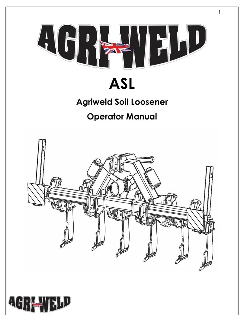
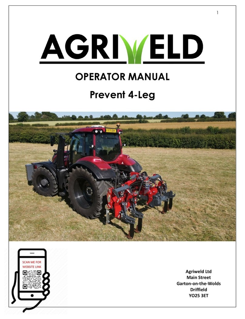
Agriweld 3M Multi Till 5T User manual

1
OPERATOR MANUAL
3M Multi Till 5T

2
Contents
Page 4
User Information, Qualification & Training
Page 5
Think Safety
Page 6
Rules Of Conduct for General Operation
Page 7
Attachment and Adjustment
Page 8
Order of Operation
Page 9
3M Dimensions & Weight
Page 10
Replacing Snap Bar & Hook-On Shear Leg Assembly
Page 11
Wearing Parts
Page 12
Replacing The Points
Page 13
Hydraulic System rules of conduct & Attachment of Folding
Hydraulic Pipes
Page 14-16
Auto Reset break back
& components
Page 17-18
Parts List
Page 19
Hydraulic Folding Diagram & Procedure
Page 20
Hydraulic Packer Depth Adjustment
Page 21
Main Assembly
Page 22
Electric Light Assembly
Page 23
Parallelogram Adjustment & Assembly
Page 24
Double Disc Frame Assembly
Page 25
Gathering Disc Assembly
Page 26
Packer Attachment
Page 27-28
Packer Assembly and parts list
Page 29
Scraper Assembly & parts list
Page 30
Stabilising Leg Assembly
Page 31 - 32
Maintenance & safety
Page 33
Road traffic regulations
Page 34-36
Risk Assessment
Page 37
Decals/stickers
Page 38
Warranty

3
Page 39
CE Declaration
Page 40
Your notes

4
USER INFORMATION
This manual contains basic advice, generic to all Agriweld Multi Till 5T machines, which
should be observed during setting-up, operation and maintenance. It must be read by
all personnel who may operate this machine prior to use and be available at all times to
each potential operator.
If safety instructions are not complied with, it can lead to the risk of injury to yourself and
others as well as damage to the environment or to the machine. Non-compliance to the
safety instructions can also lead to claims for damages becoming invalid.
New equipment - be careful!
It is very important to be careful when new equipment is going to be used for the first
time. Incorrect mounting of equipment and operational errors can lead to expensive
repair work and operational losses.
Your warranty with Agriweld is not valid if the instructions in this operating manual are not
followed correctly.
QUALIFICATION AND TRAINING
•Experienced* personnel only may perform any work on, or with the machine.
Statutory minimum age limits must be observed.
•Only trained and instructed staff, with the correct certification or licence to use,
operate, set up and maintain this machine should be authorised to do so.
Individual responsibilities of personnel concerning operation, setting up,
maintenance and repair must be clearly established.
•Define the machine operator’s responsibilities – also with regard to observing
traffic regulations. The operator must have the authority to refuse any instructions
issued by third parties, which contravene safety.
•Persons undergoing training or instruction should not be allowed to work on or with
the machine unless they are under the constant supervision of an experienced
person.
•The use of spare parts, accessories and ancillary equipment not supplied and/or
not approved by Agriweld could have detrimental effects to this machine or its
functions and hence impair the active and/or passive driving and/or operational
safety (accident prevention).
•Agriweld shall not be liable for any damage caused by the use of spare parts,
accessories and ancillary equipment not supplied and/or approved by Agriweld.
•Conversions of, or modifications to the machine may only be carried out after
consultation with Agriweld.

5
*Experienced persons are classed as those individuals who have been trained, have current
knowledge and skills or have participated in the use of the type of activity and equipment
for several years.
SAFETY INSTRUCTION
Read the instruction manual and follow the instructions given.
Take care when hitching up or unhitching the machine to and from the tractor via the
linkage
It is forbidden to allow any persons to sit or ride on the implement at any time
The tractor should be fitted with enough front-end weights for stability and to maintain
secure steering. This is dependent upon many variables, including those such as ground
conditions, working depth and soil type, etc.
Driving, steering and braking characteristics are influenced by mounted machines and
ballast weights. The operator must ensure adequate steering and braking ability
Use the tractor’s position control when coupling the implement to the tractor.
Do not stand between tractor and implement during connection or while it is being
raised/lowered on the tractor linkage.
The tractor's lower link arms should be stabilised before driving on a public road so that
the implement and tractor lower link arms do not touch the tyres during transport.
Make sure that all nuts and bolts are always fully tightened.
NEVER stand or work beneath a suspended load unless the full weight of the machine is
supported fully by suitable chocks or stands capable of carrying the implements entire
weight and bulk.
The user is responsible for ensuring the implement complies with the law when driving on
public roads and to check each time before taking the implement on the highway that
the lights are in full working order.
Always lower the implement when attached to a tractor whilst parked.

6
DANGERS, OPERATING ERRORS AND EXEMPTION FROM LIABILITY
1. No responsibility will be accepted for possible dangers arising from operations
complying with the designated use.
2. Agriweld shall not be liable for any damage to agricultural produce and other items,
which occurs as a result of normal operating, adjustments errors, failure by any means
or incorrect usage.
3. Agriweld accepts no liability for any damage caused as a result of operations not
complying with the designated use of the machine. This also applies to damage to
agricultural produce caused by certain external influences, which cannot be avoided
with the current state of the art.
RULES OF CONDUCT FOR GENERAL OPERATION
The following points must always be observed before the machine is started up and
during operation:
-Read the risk assessment and operator manual thoroughly.
-Only experienced and trained personnel should use this machine
-Never leave the machine unattended.
-Check the machine regularly for oil leakage. Replace defective
components immediately.
-Do not use if any parts are found defective.
-Check the machine for dirt accumulation and keep the machine clean.
-Perform regular maintenance checks to ensure faults are noticed quickly.
-Perform a regular greasing routine. The machine needs to be well greased
at all times.
-Replace wearing points in good time so not to cause damage elsewhere.

7
ATTACHMENT AND ADJUSTMENT
Attach the Multi Till 5T Subsoiler to the tractor using the rear linkage. It is important to the
function of the Multi Till 5T to ensure that the machine is running level to allow optimum
level of soil disturbance and to prolong the lifespan of the wearing parts. To do this please
adjust the frame up or down in the horizontal axis to ensure the main frame is running
parallel to the ground.
Connect the light unit using the 7 pin plug fitted to the back of the tractor and test the
lights to ensure they are working correctly - you may need another person to help you
ensure the rear brake lights and indicator lights are working as they should.
Please ensure that the implement is mounted correctly to the tractor rear linkage before
use.
For folding and/or auto-reset machines only: Connect the hydraulics to the tractors rear
hydraulic supply using the pipes and fittings provided with the Multi Till. Check that the
hydraulic hoses are free of damage and not routed in a position to fowl when lifting and
lowering the Multi Till on the tractors linkage. Only connect or disconnect the hydraulic
pipes to and from the tractor when the oil pressure in both the tractor and implement has
been released. See page 10 for hydraulic folding instructions
Check that all nuts and bolts are correctly tightened and none are missing.

8
Order of operation
ATTENTION –Due to the nature of the Multi Till a strict order of operation must be
adhered to. Failure to follow the order of operation may result in damage to the
machine.
In the field
1. Lower the drawbar
2. If required now is the time to insert any required spacers on the packer
frame and disc frame to set depth.
3. Rotate the packer frame into work, until it hits the stop. Are you happy
with the setting? If not add or remove spacers.
4. When you are happy with the setting of the roller, lift the drawbar
5. Lower the legs and disc frame until they stop.
6. When ready to begin, lower the frame into work on the drawbar.
7. Ensure all parts of the machine are running at the heights and depths
required. Adjust if needed or proceed.
Turning on a headland
From the in-use position in the field;
1. Simply lift the legs and discs out of work using the drawbar
2. DO NOT flip the machine on to the transport wheels, it should be turned
whilst rolling on the packer.
Transport
From the in-use position in the field;
1. First lift to rotate the packer and fully lower the transport wheels.
2. Lift the drawbar so that the legs and discs are clear of the ground.
3. Retract the legs and lift the discs.
4. Lower the drawbar so it is a safe height for traveling down the road.
5. Before traveling down the road ensure that the rear draw bar is at a
height that is suitable for any machine that is being towed behind.

9
7.8M
WEIGHT: 4200Kgs
3M Dimensions and weight

10
SNAP BAR REPLACEMENT (if relevant)
SAFETY FIRST:
When replacing the snap bar after shearing, ensure the legs
are raised just out of work sufficiently so that the leg falls back
into position to allow the snap bar to be removed/replaced.
The tractor should be stationary and the engine turned off to
ensure the operator is safe to perform the adjustments
required. No tools are needed and replacing the snap bar is a
single man procedure.
TO REPOSITION SNAP BAR:
Remove both linch pins, take off and dispose of broken piece.
Relocate remaining snap-bar to the next available position. Re-
fit Linch pins and continue.
Leg Socket Pivot
Bush
M24 x 100
M24 Washer
M24 Nylock Nut
M10 x 50
M10 Nylock
8mm Linch Pins
Snap Bar
Hook On Shear Leg Assembly

11
WEARING PARTS
Replace wearing parts before excessive wear as this causes poor performance and
damage to the leg. The wearing parts used on the implement can vary according to
the required use although as standard the Multi-Till is fitted with a low disturbance one-
piece MDT ‘Low Disturbance’ style point. Parts can be obtained through Agriweld Ltd
directly or through your local dealer.
Acquiring spare parts
Please quote the details listed on the implements serial plate as well as the machine’s
serial no. on every enquiry or order for spare parts/ accessories, or for enquiries of a
technical nature.
The use of spare parts supplied by other sources shall only be permitted after
consultation with the manufacturer. Original spare parts and accessories authorised by
the manufacturer (Agriweld Ltd) ensure safe and reliable operation. The use of parts
supplied by other companies may invalidate the liability of the implements
manufacturer for any consequences arising from the use, failure or injury caused by
unauthorised parts.
Disposing of replaced parts
The following points should be observed before replacing or disposing of parts.
-Replaced parts, which still function, should be cleaned and stored in an
orderly manner for re-use.
-Any implement parts, which cannot be repaired should only be disposed of
at an appropriate collecting point or be collected by a scrap metal
merchant.
-So-called “valuable” materials should be disposed of in the correct and
proper way, i.e. plastics, rubber, scrap metal, etc. should be recycled.
-Collect and dispose of old oil in accordance with the current regulations.

12
REPLACING THE POINTS
Only personnel with the appropriate experience* should perform these changes.
It is only permitted to replace the points on solid ground for e.g. Cement/tarmac, to
avoid the risk of sinking and potential injuries whilst performing the changes. The
implement must be raised on the tractor linkage and the tractor engine turned off.
Remember to use the parking brake and/or wheel chocks to ensure that the tractor is
held stable. It is important to support the implements weight with stands/chocks strong
enough to support the implements full weight and bulk in the event of a failure of the
tractor hydraulic system. Ensure that no one can start the tractor and its hydraulic
system accidentally by locking the cab door. It is prohibited to work under a suspended
load.
Only when you are confident that you have met the safety standards required you can
proceed;
Unbolt each worn point in turn to free it from the leg by removing the M10 nyloc nut
and the M10 x 50mm long bolt. The point will be free to remove. A new point can then
be replaced into the same position using the same M10 nyloc nut and M10 x 50mm
long bolt. Ensure the fixings are tight but not overtight.
For CAST points (provided as standard) ensure that the fixings are NOT over tightened to
prevent potential damage. The point casting may crack if overtightened.
When you have finished replacing all required points, remove the supporting
chocks/stands and lower the machine as in the Think Safety Section above until it is safe
to move off.
M10 Nylock nut
M10 x 50mm long
bolt
GLS Point

13
HYDRAULIC SYSTEMS
Rules of conduct when handling the hydraulic system
DANGER!
The hydraulic system is under high pressure! Fluids escaping under high pressure can
penetrate the skin and cause serious injuries. If any such injuries occur, always seek
medical treatment/advice immediately.
Important:
Only experienced* and/or trained personnel may undertake any repairs or
maintenance on the hydraulic system.
Only work only on the hydraulic system when the hydraulic system is depressurised and
the drive is switched off.
It is especially important that all hoses and connections are checked frequently for
leakage and any visible external damage. Porous and defective hoses must always be
replaced immediately. DO NOT ATTEMPT TO REPAIR THEM.
The hydraulic hoses should not be connected to, or removed from the hydraulic system
on the tractor unless the oil pressure in both the tractor and implement has been
released.
Oil leakage from damaged hoses and connections can cause fatal injury and possible
fire risk.
ATTACHMENT OF HYDRAULIC FOLDING PIPES (Hydraulic Folding Models Only)
Once the implement is attached to the rear of the tractor, plug the hydraulic folding
pipes into the tractor spool. Only when in the field and prior to working, operate the
spool to lower the wings until they stop. The valve fitted to the hydraulic cylinders
(folding) locks the wings in position and will not move until oil pressure is supplied again.
If the wings appear to be sagging or uneven, Agriweld can supply adjustment stars to
level the machine.
Always transport a hydraulic folding cultivator in its folded position.

14
AUTO RESET (Applicable to auto-reset models only)
The auto reset pressure is set around 50 bar for dispatch. You will need to adjust this
setting to your own conditions. If the legs trip too easily or constantly, the pressure can
be increased. If the legs do not trip at all the pressure requires decreasing to prevent
damage, which will not covered under warranty. Please see Charging Oil Pressure
below for instructions. PLEASE NOTE: The pressure may need adjusting for different
working locations as soil conditions can vary.
Prior to each use, the pressure should be visually checked to ensure that it has not
reduced or whether adjustment is required. The pressure gauge is situated under the
headstock on the main frame. If for any reason the pressure has reduced, the machine
can still be operated but excessive tripping of the legs may occur, and it will need re-
charging from the tractor. Please see Auto Reset Break Back Adjustment on following
page.
AUTO RESET SYSTEM –IMPORTANT - Break back adjustment
The auto reset system (if applicable to your model) will be pre-set to a standard pressure
on dispatch (around 50 bar). On first use, if the system is tripping either too often/easily or
does not trip at all, it will require adjustment to work effectively and prevent damage to
the machine which is NOT COVERED UNDER WARRANTY if the machine has been run at
too higher pressure and has failed to trip. It is necessary to adjust the system in small (5
BAR MAX) increments either way. IMPORTANT: An overly high pressure can result in
damage to the equipment. Continued over.

15
AUTO RESET SYSTEM –Break back adjustment continued (if applicable)
1. Remove topmost valve cap –17mm spanner required
2. Slacken lock nut –17mm spanner required
3. Run the hydraulic service on tractor
4. Using Hex key turn inner grub screw (located under the cap) - 5mm size required
i. Clockwise to increase pressure
ii. Anti-clockwise to decrease pressure
i. Use pressure gauge to assess the increase/decrease in resistance
from the auto reset system.
5. Stop running the hydraulics on the tractor
6. Retighten lock nut
7. Replace cap
8. Set the tractor to float on this service. Alternatively disconnect the hydraulic feed
pipes for the auto reset system safely.
9. The new pressure is now locked in.
It is necessary to adjust the system in small (5 BAR MAX) increments either way.
IMPORTANT: An overly high pressure can result in damage to the equipment.
Top cap
Lock Nut
Pressure
gauge

16
Auto Reset Leg & Socket Components (if relevant)
5
4
12
13
18
6
2
7
8
9
1
3
10
14
11
15
15
16
17
19

17
Item
Number
Part Number
Description
Quantity Per
Assembly
1
705/100
Hydraulic Ram
1
2
AR_HOSL_002
Upper Socket
Assembly
1
3
AR_HOSL_001
Lower Socket
Assembly
1
4
AR_HOSL_LEG
Low Disturbance
Leg
1
5
GLS_POINT
Low Disturbance
Point
1
6
30x40x40_OB
Oillite Bush
2
7
M24_NY_NUT
M30 Nylon Nut
2
8
M24_Washer
M30 Washer
4
9
M24_BOLT_80
M24 x 80mm Bolt
2
10
M30_Washer
M30 Washer
1
11
Z325074KR
Leg Pin
1
12
AR_Ram_Upper_002
Upper Ram Pin
1
13
AR_Pivot_Pin
Socket Pivot Pin
1
14
AR_Ram_Lower_002
Lower Ram Pin
1
15
LP8KR
8mm Linch pin
2

18
16
M12_50mm_Bolt
M12 x 50mm Bolt
1
17
M12_40mm_Bolt
M12 x 40mm Bolt
1
18
M12_Washer
M12 Washer
4
19
M12_Ny_Nut
M12 Nylock Nut
2

19
HYDRAULIC FOLDING DIAGRAM (Hydraulic folding models only)
4 way diverter
50/50 flow divider
Feed
Feed
HYDRAULIC FOLDING PROCEDURE (Hydraulic folding models only)
UNLOCKING is required prior to unfolding. Unlock the tap on each hydraulic ram.
Thereafter, use the hydraulic service to unfold the wings.
LOCKING, once the wings are fully folded ensure the locking taps are fully in the locked
position. DO NOT TRANSPORT IN FOLDED POSITION UNLESS THE WINGS ARE FULLY LOCKED
IN POSITION.
Locking Tap
(Open)
Unfold
Fold

20
HYDRAULIC PACKER DEPTH ADJUSTMENT
DEPTH ADJUSTMENT: The depth of the packer can
be easily adjusted by adding or removing spacers.
Maximum depth is achieved when all spacers are
used. Adding spacers will increase the working
depth.
To add or remove spacers you MUST fully lift the
packer. Add /remove the required number of clips
and lift the packer until it hits the new spacers.
Run the machine and make sure the machine
is at the required depth, add or remove
more spacers if needed.
Spacers
706/2 Ram
Table of contents
Other Agriweld Farm Equipment manuals
Popular Farm Equipment manuals by other brands

Blue Diamond
Blue Diamond MOLDBOARD PLOW 440012 Operation and maintenance manual

DALBO
DALBO TRIMAX 520 user manual

Tube-Line
Tube-Line BF5000SL Operator's manual

Tube-Line
Tube-Line TL5500 2004 owner's manual

DALBO
DALBO MINIMAX 950 User instructions

Blue Diamond
Blue Diamond Mini Series Operation and maintenance manual