1. INTRODUCTION
This manual is a part of machine and at the same time you
can consult to manual for using the machine safely and
efficiently during the entire duration of use. Therefore it should
be stored carefully in a safe place.
Users must read and apply the rules for safety and prevent
from possible accidents. The machine must be used by
competent people who read the manual carefully.
Using the machine with favorable conditions for safety of
people and environment is the responsibility of user.
Please consder that t s user’s responsblty to check that
the machne s operated only n optmum condtons of safety
for people, envronmental health, anmals and property.
2. DESCRIPTION OF THE MACHINE
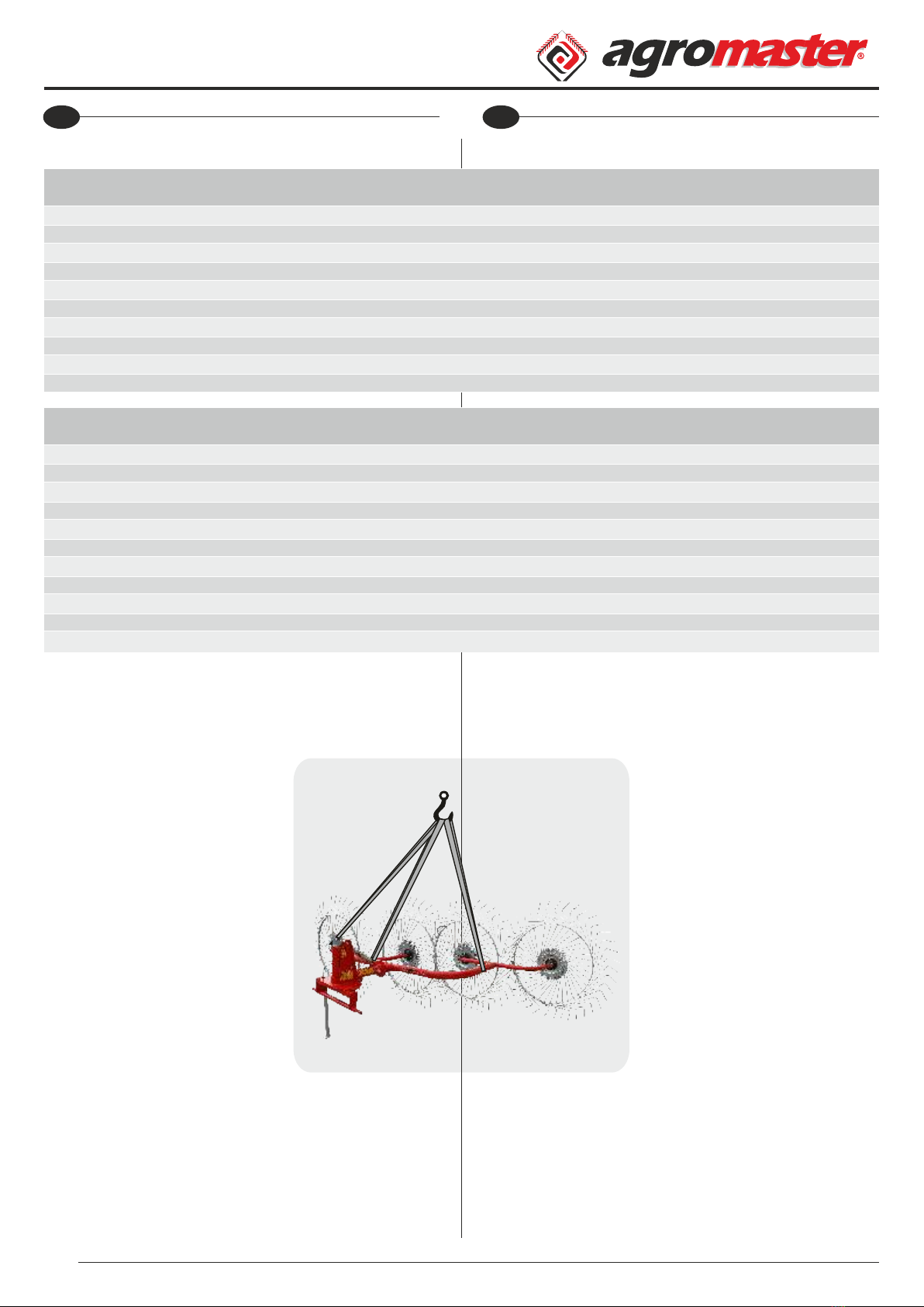
The mounted type of machine is produced with 2-3-4 and 5
drums. This implement has been designed and produced to
move forage that has previously been cut and form windrows
or turn the forage for airing if and when necessary. It is suitable
as an implement for tractors of adequate horse power and
weight. The choice of the implement must be made within the
limits accepted by the tractor manufacturer based on weight
and dimensions as per the chart to be found on "Technical
Specications".
2.1. AREAS OF USAGE
Move forage that has previously been cut and form
windrows or turn the forage for airing which this process can
be done on eld.
This machine may not be used for any other applications as
above mentioned.
This implement must be used only in adequate day light or
adequate lighting must be supplied from the tractor directly
onto the implement and its immediate surroundings.
4
WARNING
Other usages which are not stated on
the manual not only can harm the
machine but also give cause for serious
damages for the user.
EN Operator's Manual
OT
Kullanım Kılavuzu
TR
1. GİRİŞ
Bu ktap aynı zamanda maknenn br parçası olup, tüm
kullanım süres boyunca güvenl ve verml br kullanım çn
danışableceğnz ve blg ednebleceğnz br kaynak
ntelğndedr. Bu yüzden dama güvenl br yerde özenle
saklanmalıdır.
Kullanıcı ve müşter, kend güvenlğ çn belrtlen güvenlk
ve olası kazalardan korunma kurallarını dkkatlce okumalı ve
uygulamalıdır. Bu yüzden her koşulda makne, bu ktapta yer
alan teknk blgler kaza önlemlern tamamıyla ve dkkatlce
okuyan, yeterl blgye sahp uzman kşlerce kullanılmalıdır.
Unutulmamalıdır k maknenn nsan, çevre sağlığı, hayvan
ve mal mülk güvenlğ çn en uygun şartlarda kullanıldığının
takp edlmes ve kontrolü, kullanıcının sorumluluğundadır.
2. MAKİNE HAKKINDA TEMEL BİLGİLER
Maknenn asılı tp 2-3-4 ve 5 tırmık tekerl olarak
üretlmektedr. Bu ekpman önceden bçlmş olan otu
toplamak ve namluyu dağıtmak ya da alt üst etmek çn
tasarlanmış ve üretlmştr. Yeterl beygrgücü ve ağırlığı olan
traktörler çn uygun br ekpmandır. Ekpman seçm, “Teknk
Özellkler” de bulunan çzelge doğrultusunda, ağırlık ve
ölçülere dayalı traktör üretcs tarafından kabul edlmş sınırlar
çersnde yapılmalıdır.
2.1. KULLANIM ALANLARI
Önceden bçlmş olan otu toplamak ve namluyu dağıtmak
ya da alt üst etme gb şlemler yapılablmektedr.
Bu makne yukarıda belrtlenler dışında dğer uygulamalar
çn kullanılamaz.
Bu ekpman sadece yeterl gün ışığında kullanılmalıdır ya da
yeterl aydınlatma traktör tarafından ekpmanın üzerne ve
hemen yanına drekt olarak sağlanmalıdır.
UYARI
Bu ktapta belrtlen kullanımların
dışında herhang br kullanım, makneye
zarar verebleceğ gb kullanıcı çn de
cddî tehlkelere sebep olablr.
3. GUARANTEE
• On delivery, check that the equipment has not been
damaged during transport and that the accessories are
integral and complete.
• The purchaser will enforce his rights on the guarantee only
when he has respected conditions concerning the benet of
guarantee.
• The guarantee is valid for one year, against all defects of
material from the date of delivery of the equipment.
• The guarantee does not include working and shipping
costs.
• Obviously, all damage to person or things are executed
from guarantee.
• The guarantee is limited to the repair or replacement of the
defective piece, according to the instructions of the
Manufacturer.
• Dealers or users may not claim any indemnity from the
Manufacturer for any damage they may suffer (because of
costs for labour, transport, defective workmanship, direct or
indirect accidents, lost of earnings on the working positions,
etc.)
3.1. EXPIRY OF GUARANTEE
Guarantee expires:
• If limits set out in technical data table are overshot.
• If instructions set out in this booklet have not been
carefully followed.
• If the equipment is used badly, defective maintenance or
other errors by client.
• If original spare parts are not used.
5
ATTENTION
• The customer should instruct
personnel on accident risks, on the
operator safety devices provided, on
noise emission risks and on general
accident prevention regulations
provided for by the international
directives and by the law in the country
in which the machines are used.
• In any case, the machine should be used exclusively by
skilled operators who will be held to follow scrupulously the
technical and accident - prevention instructions in this
manual.
• It is the user's responsibility to check whether the machine is
operated only in optimum conditions of safety for people,
animals and property.
EN Operator's Manual
OT
Kullanım Kılavuzu
TR
3. GARANTİ
• Teslm aldığınızda maknenn taşıma sırasında hasar görüp
görmedğn, parçaların tam ve eksksz olduğunu kontrol
ednz.
• Alıcı, yalnızca garant kurallarına uyduğu takdrde
garantden yaralanablr.
• Malzemeden kaynaklanan arızalara karşı garant,
maknenn teslm tarhnden tbaren br yıl çn geçerldr.
• Garant, çalışma ve naklye ücretlern kapsamaz.
• İnsanlara ve eşyalara olan zararlar garant kapsamı
dışındadır.
• Garant, arızalanan parçanın üretcnn talmatları
doğrultusunda onarılması veya değştrlmes le sınırlıdır.
• Bayler veya kullanıcılar, (şçlk ve taşıma masraarı, kusurlu
şçlk, doğrudan veya dolaylı kazalar, çalışma esnasında kazanç
kaybetme gb) zararlardan dolayı üretcden herhang br
tazmnat talep edemezler.
3.1. GARANTİNİN BİTİŞİ
• Teknk tabloda gösterlen sınırlar aşılırsa;
• Bu kılavuzda belrtlen talmatlar dkkatlce takp
edlmezse;
• Hata kullanıcıdan kaynaklanırsa, makne yanlış kullanılırsa,
hatalı bakım yapılırsa;
• Orjnal parçalar kullanılmazsa, garant sona erer.
DİKKAT
• Müşter, kaza rskler, verlen operatör
güvenlk chazları, gürültü emsyon rsk
konusunda ve uluslararası drekter ve
mak n e n n kullanıldığı ül k e n n
kanunları doğrultusunda düzenlenen
genel kaza önleme yönetmelkler le
lgl personel blglendrmeldr.
• Her durumda, makne, bu kılavuzdak teknk ve kaza önleme
talmatlarını dkkatl takp edecek yetenekl operatör
tarafından kullanılmalıdır.
• Maknenn nsan, hayvan ve mal güvenlğ çn en y
koşullarda çalıştırılıp çalıştırılmadığını kontrol etmek
kullanıcının sorumluluğundadır.