WARNING
Machine hopper should be lled with
fertilizer on the eld.
Otherwise machine can be damaged
during transportation.
WARNING
You must obey all mentioned rules in
this book otherwise you can be injured
and your machine can be damaged.
EN Operator's Manual Kullanım Kılavuzu
TR
1. GİRİŞ
Bu ktap pnömatk ekm maknesnn kullanım ve bakım
blglern ve dkkat edlmes gereken kuralları çermektedr.
Bu ktap aynı zamanda maknenn br parçası olup, tüm
kullanım süres boyunca güvenl ve verml br kullanım çn
danışa-bleceğnz ve blg ednebleceğnz br kaynak
ntelğndedr. Bu yüzden dama güvenl br yerde özenle
saklanmalıdır.
Kullanıcı ve müşter, kend güvenlğ çn belrtlen güvenlk
ve olası kazalardan korunma kurallarını dkkatlce okumalı ve
uygulamalıdır. Bu yüzden her koşulda makne, bu ktapta yer
alan teknk blgler kaza önlemlern tamamıyla ve dkkatlce
okuyan, yeterl blgye sahp uzman kşlerce kullanılmalıdır.
Unutulmamalıdır k maknenn nsan, çevre sağlığı güvenlğ
çn en uygun şartlarda kullanıldığının takp edlmes ve
kontrolü, kullanıcının sorumluluğundadır.
2. MAKİNE HAKKINDA TEMEL BİLGİLER
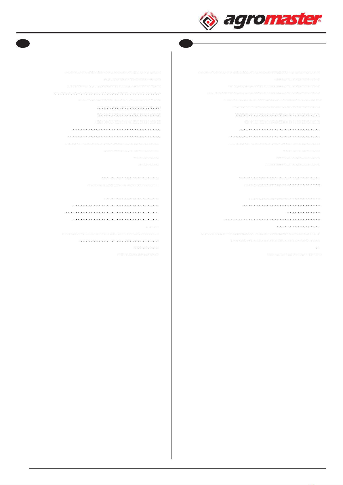
Bu makneler, 250-350, 400-500-600-800 ltre tek ve 450-500-
600-800-1000 ltre çft dskl olmak üzere, asılır tpte üretlen,
traktörün hdrolk kaldırma üntes ve ünversal 3 nokta askı
sstem le taşınablen gübre serpme maknelerdr. Bu nedenle
gübreleme yapılacak tarlaya nakl çok rahat yapılablmektedr.
2.1. Kullanım Alanları
Gübre serpme maknes buğday, arpa, yulaf, sorgum, kanola,
pamuk, pancar, ayççeğ, mısır ve fasulye gb btklere toprak
üstü gübre serpme yapması le toprağı zengnleştrr.
DİKKAT
Makneye, gübre atılacak alana
gdene kadar gübre doldurmayınız.
Gübrey, gübreleme yapacağınız
alanda doldurmalısınız.
Aks takd rde mak neye zarar
vereblrsnz.
UYARI
Bu ktapta belrtlen kullanımların
dışında herhang br kullanım, makneye
zarar verebleceğ gb kullanıcı çn de
cddî tehlkelere sebep olablr.
3. GUARANTEE
• On delivery, check that the equipment has not been
damaged during transport and that the accessories are
integral and complete.
• The purchaser will enforce his rights on the guarantee only
when he has respected conditions concerning the benet of
guarantee.
• The guarantee is valid for one year, against all defects of
material from the date of delivery of the equipment.
• The guarantee does not include working and shipping
costs.
• Obviously, all damage to person or things are executed
from guarantee.
• The guarantee is limited to the repair or replacement of the
defective piece, according to the instructions of the
Manufacturer.
• Dealers or users may not claim any indemnity from the
Manufacturer for any damage they may suffer (because of
costs for labour, transport, defective workmanship, direct or
indirect accidents, lost of earnings on the working positions,
etc.)
3.1. EXPIRY OF GUARANTEE
Guarantee expires:
• If limits set out in technical data table are overshot.
• If instructions set out in this booklet have not been
carefully followed.
• If the equipment is used badly, defective maintenance or
other errors by client.
• If original spare parts are not used.
ATTENTION
• The customer should instruct
personnel on accident risks, on the
operator safety devices provided, on
noise emission risks and on general
accident prevention regulations
provided for by the international
directives and by the law in the country
in which the machines are used.
• In any case, the machine should be used exclusively by
skilled operators who will be held to follow scrupulously the
technical and accident - prevention instructions in this
manual.
• It is the user's responsibility to check whether the machine is
operated only in optimum conditions of safety for people,
animals and property.
EN Operator's Manual Kullanım Kılavuzu
TR
3. GARANTİ
• Teslm aldığınızda maknenn taşıma sırasında hasar görüp
görmedğn, parçaların tam ve eksksz olduğunu kontrol
ednz.
• Alıcı, yalnızca garant kurallarına uyduğu takdrde
garantden yaralanablr.
• Malzemeden kaynaklanan arızalara karşı garant,
maknenn teslm tarhnden tbaren br yıl çn geçerldr.
• Garant, çalışma ve naklye ücretlern kapsamaz.
• İnsanlara ve eşyalara olan zararlar garant kapsamı
dışındadır.
• Garant, arızalanan parçanın üretcnn talmatları
doğrultusunda onarılması veya değştrlmes le sınırlıdır.
• Bayler veya kullanıcılar, (şçlk ve taşıma masraarı, kusurlu
şçlk, doğrudan veya dolaylı kazalar, çalışma esnasında kazanç
kaybetme gb) zararlardan dolayı üretcden herhang br
tazmnat talep edemezler.
3.1. GARANTİNİN BİTİŞİ
• Teknk tabloda gösterlen sınırlar aşılırsa;
• Bu kılavuzda belrtlen talmatlar dkkatlce takp
edlmezse;
• Hata kullanıcıdan kaynaklanırsa, makne yanlış kullanılırsa,
hatalı bakım yapılırsa;
• Orjnal parçalar kullanılmazsa, garant sona erer.
DİKKAT
• Müşter, kaza rskler, verlen operatör
güvenlk chazları, gürültü emsyon rsk
konusunda ve uluslararası drekter ve
maknenn kullanıldığı ülkenn
kanunları doğrultusunda düzenlenen
genel kaza önleme yönetmelkler le
lgl personel blglendrmeldr.
• Her durumda, makne, bu kılavuzdak teknk ve kaza önleme
talmatlarını dkkatl takp edecek yetenekl operatör
tarafından kullanılmalıdır.
• Maknenn nsan, hayvan ve mal güvenlğ çn en y
koşullarda çalıştırılıp çalıştırılmadığını kontrol etmek
kullanıcının sorumluluğundadır.
GS 2GS 2
1. INTRODUCTION
This manual contains pneumatic sowing machine
maintenance information and the rules that need to be
considered.
This manual is a part of machine and at the same time you
can consult to manual for using the machine safely and
efficiently during the entire duration of use. Therefore it should
be stored carefully in a safe place.
Users must read and apply the rules for safety and prevent
from possible accidents. The machine must be used by
competent people who read the manual carefully. Using the
machine with favorable conditions for safety of people and
environment is the responsibility of user.
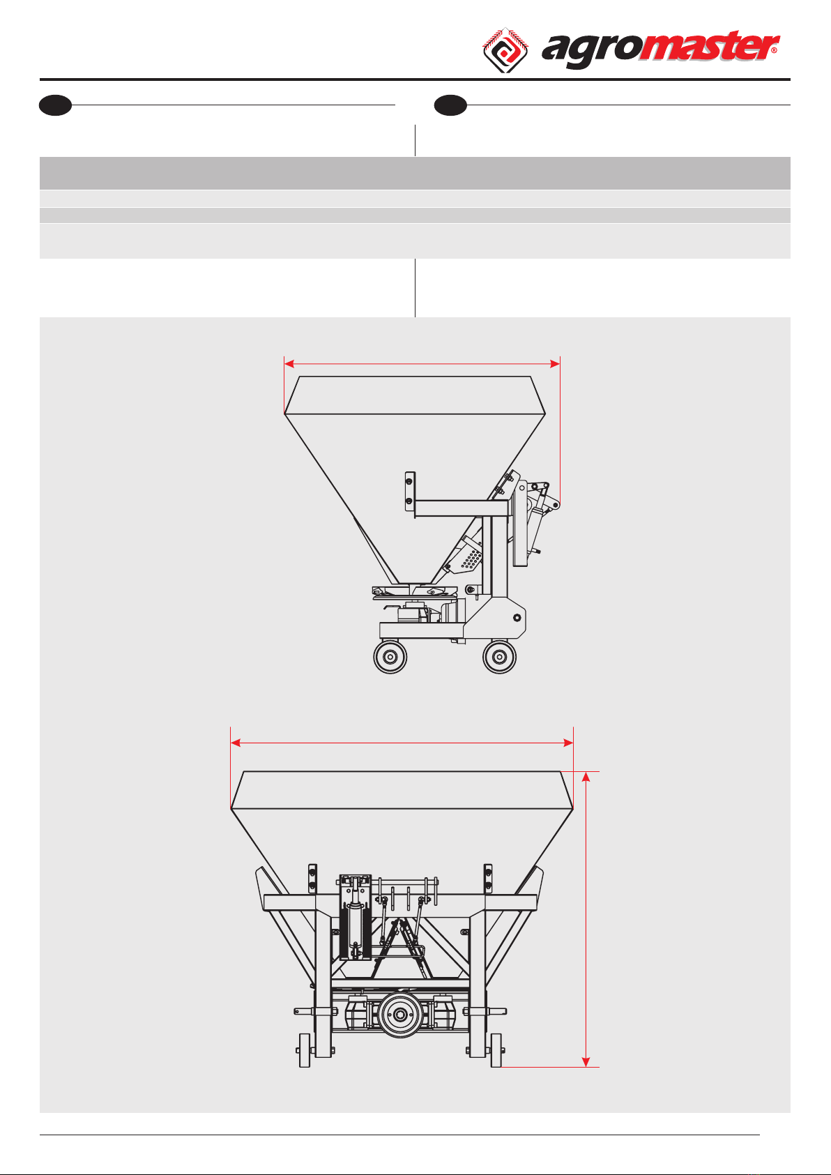
2. DESCRIPTION OF THE MACHINE
These machines are produced trailed and mounted types as
single disc with 250-350, 400-500-600-800 liters capacities and
double discs with 450-500-600-800-1000 liters capacities.
Mounted type machines are attached to tractors' universal
three point linkage system and hydraulic lifting lever
2.1. Areas Of Usage
Fertilizer spreader machine enriches the soil by spreading
the fertilizer to plants as wheat, barley, oats, sorghum, canola,
cotton, sugar beet, corn, beans, and sunower.
45