AGRU SP 315-S User manual

User’s Manual
Infrared Welding Machine
SP 315-S
P.O. Box 1108 • 655 Andover St.,Lawrence, MA 01843 • Tel: (800) 343-3618, (781) 321-5409


Version April 2008 EN 3
agru SP 315-S User’s Manual
Contents
1 Introduction........................................................................................................... 5
2 Safety Messages.................................................................................................. 5
2.1 The User's Manual ............................................................................................... 5
2.2 Explaining Icons ................................................................................................... 5
2.3 Safety Messages.................................................................................................. 5
2.4 Welder and Operator Obligations......................................................................... 7
2.5 Warranty............................................................................................................... 7
2.6 Transport and Storage.......................................................................................... 7
2.7 Identifying the Machine ........................................................................................ 7
3 Product Description and Principles of Operation ................................................. 7
3.1 Intended Use........................................................................................................ 7
3.2 Machine Description............................................................................................. 8
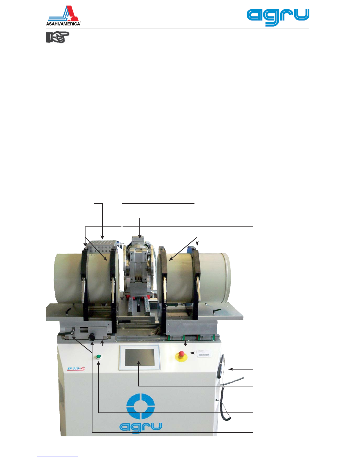
3.2.1 Component Overview........................................................................................... 8
3.2.2 Touchscreen / Control Panel ................................................................................ 9
3.2.3 Ports and Switches............................................................................................. 10
3.2.4 Specifications ..................................................................................................... 10
3.3 Welding Process Overview ................................................................................ 11
4 Operation............................................................................................................ 12
4.1 Check-out, Turning on, Selecting the Display Language.................................... 12
4.2 Entering Traceability Data for the Joint............................................................... 13
4.3 Configuring the Machine .................................................................................... 14
4.4 Changing Key Data of the Welding..................................................................... 15
4.5 Definition of Key Welding Data for Additional Materials ..................................... 16
4.6 Welding Process ................................................................................................ 17
4.6.1 Facing the Pipe Butts ......................................................................................... 17
4.6.2 Checking Pipe Alignment ................................................................................... 19
4.6.3 Pre-heating the Pipe Butts and Inserting the Heating Element.......................... 19
4.6.4 Heat-Soaking Phase .......................................................................................... 20
4.6.5 Change-over Phase ........................................................................................... 20
4.6.6 Joining Phase..................................................................................................... 20
4.6.7 Cooling Phase.................................................................................................... 20
4.6.8 End of Welding ................................................................................................... 20
4.7 Aborted Welding Process................................................................................... 21
5 Printing and Transferring Welding Reports......................................................... 22
5.1 The Print Menu and Printing/Transferring Reports............................................. 22
5.2 Showing Reports in Memory, Reprinting Tags ................................................... 23
5.3 Deleting Reports from Memory .......................................................................... 23
6 System Data....................................................................................................... 23
6.1 Setting the Date and the Time of Day ................................................................ 23
6.2 Enabling Automatic Heating ............................................................................... 23
7 Service and Repair............................................................................................. 24
8 Service and Repair Contact ............................................................................... 25
P.O. Box 653 • 35 Green Street, Malden, MA 02148 • Tel: (800) 343-3618, (781) 321-5409
Fax: (800) 426-7058 • Website: www.asahi-america.com • Email: [email protected]

Version April 2008
4 EN agru SP 315-S User’s Manual
Caution
The machine has to be operated exclusively with
a power supply line equipped with a protective
grounding conductor, as a power supply without
this safety element may cause severe machine
damage. If the machine is operated through a
power supply without a grounding conductor,
this will void any and all warranty under which
the product may be.

Version April 2008 EN 5
agru SP 315-S User’s Manual
1 Introduction
Dear Customer:
Thank you very much for purchasing our product. We are confident that
it will meet your expectations.
The development, manufacture, and check of the infrared welding machine
has been guided by our concern to offer a unit characterized by superior
operation safety and user-friendliness. The unit was manufactured and
checked according to state-of-the-art technology and widely recognized
safety regulations.
To ensure maximum operation safety, please conform to the appropriate
messages in this booklet and the regulations for the prevention of acci-
dents. Carefully read the User’s Manual to avoid damage to the machine
or hardware in its environment as well as injury.
This manual is applicable to the following machines:
agru SP 315-S
Thank you.
2 Safety Messages
This User’s Manual contains important instructions for operating safely
the infrared welding machine agru SP 315-S. Every person who operates
the machine will have to conform to the instructions of this manual.
The machine has been developed and checked with respect to welding
AGRU materials. For welding other makes, no experiential data are avail-
able and/or no liability or warranty can be assumed for the fitness and
the reliable operation of the machine.
2.1 The User's Manual
The User’s Manual is presented according to sections which explain the
different functions of the machine. All rights, in particular the right to
copy or reproduce (in print or electronic form) and distribute as well as
to translate, are reserved and subject to prior written authorization.
2.2 Explaining Icons
The following expressions and icons are used in this User’s Manual to
refer to safety-related issues:
Caution
This icon indicates that non-compliance may result in a haz-
ardous situation that possibly causes bodily injury or material
damage.
Important
This icon indicates important messages related to the correct
use of the machine. Non-compliance may cause problems of
operation and damage to the machine.
Info
This icon indicates tips and useful information for using the
machine more efficiently and more economically.
2.3 Safety Messages
Protect the power supply cord from cutting edges. Have an authorized
service shop replace damaged cables or lines immediately.

Version April 2008
6 EN agru SP 315-S User’s Manual
The machine has to be operated with a 400 V, 50/60 Hz power supply
with safety fuse or breaker of 32 A. If power is connected through a
power line manifold, the power supply has to feature an earth-leakage
circuit breaker.
The length of the power supply cord is 4 m (13 feet). The length of an
extension cable should not exceed 10 m (30 feet).
Caution
Parts Under Power
After opening the machine or removing the cover, parts of it
are accessible that may be under power. The device may be
opened exclusively by an authorized service shop.
Caution
Pipe Facing Tool
Start the pipe facing tool only when it is in its working position.
When facing pipes, do not wear jewellery; if needed, wear a
hair snood or net. It is forbidden to remove shaving from the
machine while the facing process is running. Make sure nobody
is present in this danger zone.
Caution
Heating Plate
When working with the machine, be extremely cautious while the
heating plate is operating. Since the heating plate and its guard
presents a very high temperature during the welding process, it
must not be operated if unobserved, and sufficient distance has
to be ensured to combustible materials in its surroundings. Do
not touch the heating element or the heating element guard.
Caution
Danger of Bruises and Injury
Do not remain in the danger zone while the machine opens or
closes and be sure not to have your hands between the moving
and the fixed parts of the machine. The forces exercised by
the machine are so high that it will not be able to detect and
recognize parts of the body.
Caution
Acceptable Work Conditions
The work zone has to be clean and has to have proper lighting.
It is dangerous to operate in a humid environment or close to
flammable liquids. In regard of this, acceptable work conditions
have to be ensured (e.g., sufficient distance from the machine
to other functional areas of the workshop).
Important
Power Supply Only through Line with Protective Grounding
Conductor
The machine has to be operated exclusively with a power supply
line equipped with a protective grounding conductor, as a power
supply without this safety element may cause severe machine
damage. If the machine is operated through a power supply
without a grounding conductor, this will void any and all
warranty under which the product may be.
Important
Power Only to Operational Machine
Power must never be applied to the machine before it is com-
pletely installed and ready for operation.
Important
No Foreign Bodies in Work Area
The machine must never be used if there are foreign bodies or
objects in the work area; in particular, it must not be started if
anything obstructs the smooth movement of any movable part
or component of the machine.

Infrarot-Stumpfschweißmaschine
Typ agru SP 315-S
Nr. 31506011
Netz 230V IP54 50/60Hz 1700W
Hersteller
agru Kunststofftechnik
Ing.-Pesendorfer-Str. 31
A - 4540 Bad Hall
CE Tel. +43 7258 7900
Version April 2008 EN 7
agru SP 315-S User’s Manual
Info
User’s Manual
The User’s Manual has to be available at any time on the site
where the machine is used. If the User’s Manual should come
to be incomplete or illegible replace it without delay. Feel free
to contact us for assistance.
2.4 Welder and Operator Obligations
s 4HEMACHINEMAYBEOPERATEDEXCLUSIVELYBYPERSONSWHOAREFAMIL-
iar with the applicable regulations, the guidelines for the prevention
of accidents, and the User’s Manual.
s 4HEMACHINEMAYBEOPERATEDONLYWHENOBSERVED7ELDERSMUST
have been introduced properly to operating the machine or must
have participated in a dedicated training. The operating/owning
company engages to check at reasonable intervals if the machine
is operated by the welders with the intended use and under proper
guidelines of safe work.
s 4HEMACHINEMUSTNEVERBEOPERATEDIFNOTINPROPERSTATEOFREPAIR
Before welding, the welder is required to make sure that the state
of the machine is in order.
Important
During transport, the support console of the heating element
and facing tool has to be secured with the transport locks at all
times.When installing the machine, remove the transport locks
before applying power to the machine.
2.5 Warranty
Warranty claims may be raised only if the conditions for warranty given
in the General Terms and Conditions of Sale and Shipment obtain. Fur-
thermore, the provisions and instructions contained in the User’s Manual
have to have been respected.
2.6 Transport and Storage
During transport, the machine must be at all times in the transport box
it is shipped in. Ensure that the console with heating element and facing
tool is locked during transport.
The transport box should also be used to store the machine.The machine
has to be stored in a dry location, be clean or has to be cleaned, and be
locked against unwanted operation.
2.7 Identifying the Machine
Each machine is identified by a name plate. It shows the machine model
(“Typ”), the serial number (“Nr.”), and the manufacturer.
3 Product Description and Principles of Operation
3.1 Intended Use
The agru SP 315-S Welding Machine is designed exclusively for weld-
ing plastic pipes and fittings using the infrared welding technique (butt
welding without contact).
Only the welding parameters shown on the touchscreen display (prepro-
grammed by the manufacturer or defined by the user) can be selected
for a welding operation. Any modification of the welding parameters
contained in the control software is strictly prohibited.
It is also part of the intended use to conform to the instructions provided
in the User’s Manual.

Version April 2008
8 EN agru SP 315-S User’s Manual
Important
The manufacturer can in no circumstances be held liable for damage
or consequential damage that occurs as a result of the non-com-
pliance with the procedures described in the User’s Manual, the
modification of the manufacturer-programmed welding parameters,
or non-intended use. Any such deviation or modification will cancel
any and all warranties under which the product may be.
3.2 Machine Description
The machine can be used as an in-shop installation and with anodized
aluminum components, it is also suited for clean room applications. The
machine enables users to enter the data that are relevant for the weld-
ing process and for the traceability of the welded joint. From the entered
welding parameters, it calculates the applicable forces and temperatures
and controls the welding process automatically.
All welding and traceability data are entered either directly on a touch-
screen panel or read from a bar code using a scanning pen. The welding
process in monitored in its entirety and saved to a welding report. All weld-
ing reports can the be printed or transferred to a computer with a suitable
pipeline network management software (such as DataWork agru).
Using the menus displayed on the touchscreen, the machine can be custom-
ized to the application at hand (see section 4.3, Configuring the Machine).
3.2.1 Component Overview
Heating Element
and Guard
Facing Tool
Support Console for Heating
Element and Facing Tool
Pipe Clamps
Fixed and Mobile Carriage of
Machine Frame
Touchscreen Panel
Confirmation Button for
Two-Hand Mode Steps
Scanning Pen
Emergency Stop Switch
Set Screws for Compensation of
Small Horizontal or Vertical
Alignment Gaps

29
18
500
494
200
184
agru SP 315-S26.04.08 15:09 SW022F
PVDF 315 3.1
Version April 2008 EN 9
agru SP 315-S User’s Manual
3.2.2 Touchscreen / Control Panel
Heating Phase
Ok
Nom. Force [N]
Actual Force [N]
Nom. Temp [°C]
Actual Temp [°C]
Nom. Time [s]
Actual Time [s]
Cancel
Welding Progress
Status Bar
Title Band
Multifunctional Area
(changes
depending on context of display)
- Display of/data on welding
progress
- Parameter menus to
configure operation settings
- Input keyboards
- Error messages/Notes
Navigation Bar with User
Interface Buttons
Door of Equipment and Storage
Cabinet (Reducers, Accessories)
Transport Lock Blocking Heating
Element Movement
Runner Blocks of Movable
Carriage (4 in total)
Power Supply Cord from Mains
Rail for Transport Lock and Transverse
Guiding of Support Console
Installed Transport Lock Blocking
Transverse Console and
Longitudinal Facing Tool Movement
Power Supply Cord to Facing
Tool
Power Supply Cord to Heating
Element
Runner Blocks of Support
Console (6 in total)
Runner Blocks of Support
Console (6 in total)
Ball Guide Bushing of Support
Console (4 in total)
Ball Guide Bushings of
Support Console (4 in total)

Version April 2008
10 EN agru SP 315-S User’s Manual
3.2.3 Ports and Switches
3.2.4 Specifications
agru SP 315-S
Power Supply Characteristics
Voltage
Frequency
Total Rated Power
Heating Element Power
Facing Tool Power
400 V AC ± 10%
50/60 Hz
13 kW
9 kW
1.1 kW
Welding Operation Specs
Welding Force
Speed of Facing Tool
Ambient Temperature (operation)
Ambient Temperature (storage)
Operating Range
3500 N
23 rpm
+0°C to +40°C (32°F to 104°F)
–5°C to +50°C (23°F to 122°F)
110 - 315 mm (4-3/4" - 12-1/2")
Dimensions and Weight
Dimensions (W x D x H)
Machine in transport box, w/o support legs
Machine only, excluding printer
bracket and support legs
Weight
Maximum Carriage Stroke
1400 x 1700 x 1070 mm (4' 4" x 5' 7" x 3' 6")
1045 x 1580 x 1310 mm (3' 5" x 5' 2" x 4' 3-1/2")
approx. 1100 kg
268 mm (10-1/2")
Important
The power supply connection is designed as a 3-phase plus
earth ground connection. No neutral conductor is needed.
The power supply connection should be rated at 32 amps and
should be wired with an automatic safety switch of 32 amps
medium-slow blow. The conductor section of the power supply
connection should be minimum 4 sq. mm.
Important
For the connection to mains power an approved CEE plus and
outlet have to be used and wired according to the specifica-
tions quoted above. Compare also the photograph as well as
its legend and explanations below.
Nitrogen Control
Fuse of Nitrogen
Control
Power Supply to Printer
Buzzer
Scanning Pen
On/Off Switch
Ambient Temperature Sensor
USB B Interface
(for connection to PC)
USB A Interface
(for connection to tag printer or a
USB stick)
Scanning Pen Port

Version April 2008 EN 11
agru SP 315-S User’s Manual
1. CEE Power Outlet 32 A
2. CEE Power Plug 32 A with integrated phase inverter
3. Contact Socket for Phase 3 (L3)
4. Contact Socket for Neutral (not needed with SP 315-S)
5. Contact Socket for Earth Ground (PE); a little thicker
than the other sockets
6. Contact Socket for Phase 1 (L1)
7. Contact Socket for Phase 2 (L2)
8. Contact Pin for Phase 3 (L3)
9. Contact Pin for Neutral (not needed with SP 315-S)
10.Contact Pin for Earth Ground (PE); a little thicker than
the other pins
11.Contact Pin for Phase 1 (L1)
12.Contact Pin for Phase 2 (L2)
Prior to starting to first use the machine, the power supply connection
has to be verified. Across any two phases (L1-L2, L2-L3, L1-L3) a volt-
age of 400 V AC ± 10 % has to be found. If a neutral is wired to the same
power supply socket, across any of the three phases and the neutral, a
voltage of 230 V AC has to be found. These measurement can be take
with any common voltmeter for alternating current voltages.
If connected appliances are equipped with a motor requiring 3-phase
alternating current supply, as is the case with the SP 315-S, the rotating
field of the machine has to have the proper direction.The SP 315-S checks
this and if the rotation is incorrect, a “Power Supply Error” message is
displayed. To change the direction of the rotation of the field, the phase
inverter in the plug can be used. Two of its contact pins are placed on
a grey turning disk. A flathead scredriver can be used to turn this disk,
thereby inverting the positions of the two pins, which in turn inverts the
rotation of the field.
3.3 Welding Process Overview
The welding process is performed as follows:
s 0IPESARECLAMPEDINTOTHEFRAMEDEPENDING ONTHEFORMOFTHE
component to be welded, this may mean that the outer clamps have
to be re-adjusted or that reducer inserts have to be inserted.
s 0IPEBUTTSAREWORKEDBYTHEFACINGTOOLWHICHISINSERTEDAUTOMATI-
cally, to obtain abutment along a fully parallel plane.
s 0IPEALIGNMENTISCHECKEDANDCONFIRMEDONTHETOUCHSCREEN
s !UTOMATICINSERTIONOFTHEHEATINGELEMENTWHENINSERTINGITTHE
heating element has to be clean.
s !FTERTHEHEATINGELEMENTWASINSERTEDTHEPIPESCLOSEINAUTOMATI-
cally at the predefined force.
s 7HENTHECARRIAGESCLOSEINTHEYALSOALIGNTHEHEATINGELEMENT
exactly in-between the pipe butts.
s !TTHESAMETIMETHEPIPEBUTTSAREHEATEDTOTHEPREDEFINEDTEM-
perature.
s 7HENTHEHEATSOAKINGPHASEISOVERTHEPIPESAREMOVEDAPART
and the heating element is removed automatically.
s /NCETHEHEATINGELEMENTISREMOVEDTHEPIPESCLOSEINAGAINAU-
tomatically.
s 4HISISFOLLOWEDBYASTEADYFORCEINCREASEUNTILTHEFUSIONFORCEIS
reached.
s 4HEPIPETHENCOOLSDOWNATTHEPREDEFINEDFORCE
s !FTERTHECOOLINGTIMEISOVERTHEFORCEISAUTOMATICALLYREMOVED
from the carriages and the pipe or fitting can be taken out of it.

Version 1.55
Deutsch English
Español Français
Italiano Svenska
Simp. Chinese Trad. Chinese
Japanese Korean
Русский Č
eský
not defined not defined
Version April 2008
12 EN agru SP 315-S User’s Manual
4 Operation
Important
Prior to the first use of the machine, the transport locks that
avoid longitudinal and transverse movement of the console
supporting the facing tool and the heating element have to be
removed (see photographs on page 9). An Allen wrench for
removing the transverse lock is included with the machine.
The control software of the machine monitors the transport
lock status. When the machine is turned on with the locks in
place, welding cannot be started and an
error message shows (see photograph on
this page).
Important
Whenever the machine is moved, the
transport locks have first to be installed.
Damage due to the fact that the machine
was moved without installed transport locks
is not eligible for warranty.The transport lock
may be installed and removed only when
the machine is turned off. Damage due to
non-compliance with this provision will also
disqualify from warranty.
4.1 Check-out,Turning on, Selecting the Display Language
Place the machine on a level surface and ensure it cannot slide. Suffi-
cient distance has to be kept to other areas in the workshop, especially
to those in which combustible materials are used, in order for the heating
element temperature of up to 500°C (930°F) not to be hazardous.
Depending on the piece that is going to be welded, the outer clamps may
have to be repositioned or removed. To do so, loosen the locking bolts
and either remove the clamp or re-adjust it and secure it by tightening
the locking bolts again.
If the diameter of the pieces to be welded is smaller than the clamp, insert
the reducer inserts. This can be done with the enclosed Allen key.
Important
Pipe clamps and reducer inserts have to be clean or must be
cleaned before welding starts. To insert or remove the inserts,
do not use heavy tools (hammer, wrench). They may damage
the inserts.
Important
The surfaces of the heating plate have to be free of grease and
clean, or they have to be cleaned.
Important
Make sure all connectors are tight in their sockets and make
sure that the machine is operated
only if the conditions for safe and
intended use are met (see also
section 2).
After preparing the machine for welding and
connecting the power supply cord to the
mains power supply, the machine is turned
on using the On/Off switch. The welcome
screen, as reproduced in Display 1, appears
on the touchscreen panel. Touch the appro-
priate button to select the display language
that the machine will use.
After the language was selected, the ma-
chine takes the user to the welder code entry
Display 1

1 2 3
0<- ->
4 5 6
7 98
Edit
.
+++++++++++++++++++++++++++++++++
A S D F G H J LK
CapsLock
Q W E R T Z U OI
Edit P
1 2 3 4 5 6 7 98 0
^
<----
Enter
Y X C V B N ;M?
<--
-.
-->
ATH-0023-UL776
SW026A
ASTNM+++++++++++
ABCD CORP.
Version April 2008 EN 13
agru SP 315-S User’s Manual
screen. Without a valid welder identification
code, it is impossible to start welding pro-
cesses on the machine, since the machine
is unblocked for operation only after a valid
welder identification code was entered.
Enter the welder identification code by
typing it on the touchscreen and saving it
to memory by touching the “Ok” button. If a
bar code for the welder code is available,
you can also read it from the bar code using
the scanning pen.
Info
All inputs for which a bar code is
available can be entered from the
bar code using a scanning pen.
Important
Entering data on the touchscreen must always be performed
with the bare finger. Using objects (ballpoint pens, screwdriv-
ers, etc.) may cause unrecoverable damage to the surface of
the touchscreen.
4.2 Entering Traceability Data for the Joint
After the welder identification code was entered, the traceability data for
the joint have to be entered.The machine
displays the traceability data for the last joint
that was welded (see Display 3), which can
be re-used for the next welding operation by
simply touching the “Ok” button.
If traceability data are not the same as for
the last joint, change the data that are dif-
ferent by touching the appropriate “Change”
button. Depending on the kind of data you
want to change, the machine displays either
a numeric keypad (see Display 2) or an
alphanumeric keyboard (see Display 4). To
confirm and save your data input to memory,
touch the “Ok” button.
Info
Depending on the software version
installed in your machine, some
screens may differ slightly on your
machine from the reproductions in
this manual.
When the traceability data were entered, the
machine displays the first input screen of the
welding process proper (see Display 5). In
this display, it is possible to start the welding
process and to customize the configuration
of the machine.
When going on from traceability data input
to the welding process proper or the input
of characteristic welding data, the machine
perform a calibration of the points of refer-
ence for its movable parts. Make sure this
short process is not interrupted.
Enter Welder Code
agru SP 315-S 26.04.08 14:54 +++++
OkCancel
Display 2
Display 4
Enter Commission Number
OkCancel
Commission No.
Welder Code
Additional Data/Addresses
Installing Company
Change
Change
Change
Change
agru SP 315-S 26.04.08 14:55 J.Doe
Last Traceability Data
Ok
Display 3
agru SP 315-S 26.04.08 14:55 +16°C

1 2 3
0<- ->
4 5 6
7 98
Edit
.
++++++
Version April 2008
14 EN agru SP 315-S User’s Manual
The welder will enter all settings and per-
form all control actions on the touchscreen
panel.
4.3 Configuring the Machine
In the first input screen of the welding pro-
cess proper (Display 5), the key data of the
last welding are shown (material, diameter,
and wall thickness of the welded pipe).
Furthermore, the status bar at the top of
the screen shows the date, time of day, and
also either the current ambient temperature
or the power supply voltage or the welder’s
name or code.
In Display 5, the welder has the possibility
to:
s IMMEDIATELYSTARTAWELDINGPROCESSTHATWILLBEPERFORMEDWITHTHE
same welding parameters as the previous welding (touch the “Ok”
button and move on to section 4.6);
s ENTERNEWPIPERELATEDDATAFORTHENEXTWELDINGTOUCHTHEh.EWv
button and move on to section 4.4);
s CHANGETHEMACHINESETTINGS INTHE
configuration menu (touch the “Menu”
button);
s TOREADANEWWELDER)$CODEUSINGTHE
scanning wand; or
s DISPLAYTHEDATEFORTHENEXTSCHEDULED
maintenance on the screeen by touch-
ing “New” button for some time.
Info
When the confirmation pushbutton
on the front is touched simultane-
ously, the three button in Display 5
have the following functions:
New Locking the machine, so it will only
be able to use it again by entering a
valid welder identification code.
Menu Closing in the movable carriage of
the machine toward the center (“closing” the machine).
Ok Moving the movable carriage apart toward the edge (“opening” the
machine.
The first five options of the configuration menu are immediately acces-
sible, the other options will be displayed only after an access code for
the machine, the so-called selection code, was entered (see Display 6).
The menu has the items listed in the following table. To toggle between
various possible settings, or to open a sub-menu for a given menu item,
touch the appropriate button.
Info
Some of the buttons next to menu option change their color
when they were pressed and are then displayed as though the
button is held down. In this case the “held down” button mean
that this menu option is the selected option.
Designation Setting Description / Data to be entered
Number of Tags Menu In a sub-menu, the number of tags to be printed for sticking them
onto the welded pipes, can be selected.
Show Reports Menu In a sub-menu, it is possible to select a job number in order to
display the welding reports of this commission. In report display
mode, it is also possible to print a label tag for this welding once
again (see section 5.2).
agru SP 315-S 26.04.08 14:53 J.Doe
Use material parameters of last operation?
OkMenuNew
Material
Diameter
Wall thickness
PVDF
315mm
2.1mm
Display 5
PVDF
315mm
2.1mm
Selection Code
agru SP 315-S 26.04.08 14:54 +16°C
Ok
Cancel
Display 6

Version April 2008 EN 15
agru SP 315-S User’s Manual
Unit of Length
(mm / inch)
Menu In a sub-menu, the unit of length used for displaying and saving
welding data can be selected.
Temperature Unit
(°C / °F)
Menu In a sub-menu, the temperature unit used for displaying and saving
welding data can be selected.
—— New Page in Menu ————————
Automatic Heating Menu In a sub-menu, a time, for instance on the following morning, can be
pre-set when the heating element will start heating up automatically
(see sub-section 6.2).
Alarm Sound On / Off By touching this button, the alarm sound that the machine emits to
validate the execution of a given step in the process can be enabled
or disabled. Whatever this setting, the sound will be heard to indicate
the imminence of the change-over phase.
Select Langauge Menu In a sub-menu, the language in which display texts and reports are
edited can be selected.
—— New Page in Menu ————————
Memory Control ON / OFF if ON: Machine stops when the memory is full;
if OFF: Machine overwrites the oldest report when the memory is
full.
Machine Parameters Menu In a sub-menu, the machine number can be entered and the
temperature of the heating mirror and the welding force can be
zeroed/calibrated.
Access to this sub-menu requires an additional access code that is
available from the manufacturer/distributor.
Date/Time Menu In a sub-menu, date and time can be set.
Delete Reports Menu In a sub-menu, it is possible to delete all welding reports currently in
memory.
To access this sub-menu, the so-called selection code is required
(see at the beginning of this sub-section); the reports will be deleted
only after another safety warning was confirmed.
—— New Page in Menu ————————
Additional Materials Menu In a sub-menu, the key data for welding can be defined for pipe
materials that are not available yet.
4.4 Changing Key Data of the Welding
In the welding-individual start screen (see Display 5), it is possible to
change the weld-specific key data for the joint to be welded. To do so,
touch the “New” button. The screen that allows selecting the material of
the pipes that are going to be welded, is then displayed on the touch-
screen panel (see Display 7). To select a material, touch the appropriate
button on the screen.
Default Materials are those pipe materials that are defined by default
when the machine is shipped. Additional
Materials, if any, are those pipe materials
that were defined by the user in the defini-
tion screens accessible from the appropriate
configuration menu option (see section 4.5).
The maximum number of additional materi-
als is three.
When the appropriate button was touched to
select a pipe material, the screen changes
and displays the selection of pipe diameters,
with default and additional diameters just
as for the materials. Finally, a third, similar
screen allows selecting the appropriate wall
thickness.
Display 7
Select 'Material'
Add. DataCancel
agru SP 315-S 26.04.08 14:55 +16°C
ECTFEPP-nPPPVDF
PFA
PVC
Default Material
Addit. Material

Version April 2008
16 EN agru SP 315-S User’s Manual
Note that a screen will not appear if it would not make sense to display it.
For instance, if only one wall thickness is defined for a given pipe diam-
eter, the wall thickness selection screen will not show. Moreover, when
you select an additional material, this has to be confirmed by entering
the so-called selection code (see sub-section 4.3). Default materials can
be welded without entering this code.
Important
The machine must never be used to weld pipe materials, di-
ameters, and thicknesses other than those available in the key
welding data screens.The manufacturer is in no circumstances
liable for damage or consequential damage that occurs as a
result of deviations from these pipe data or of modifications or
attempted modifications to the control software. Furthermore,
this will cancel any claims to warranty expressed for the ma-
chine. To make a material available in this screen, it has to be
entered previously with all its technical welding parameters in
the configuration menu.
Info
Welding PFA pipes is subject to a valid license for this pipe ma-
terial. Therefore, when this material is selected (either from the
default materials or from the additional materials, if defined), a
message to this effect is displayed. The license key is disclosed
either by the manufacturer or the distributor of the machine or
when you purchase the PFA pipes and can then be entered in
the machine parameters.
In all screens that allow changing the key data for the welding operation,
by touching the “Additional Data” button, it is possible to access the ad-
ditional traceability data and change them as needed.
4.5 Definition of Key Welding Data for Additional Materials
The configuration menu (see section 4.3) has an option “Additional
Materials,” which allows defining the key data the machine should use
when welding pipes of a material that is not currently available in the
machine.
If no additional, operator-defined pipe material has been saved to system
memory, the unit displays an input screen that allows entering the name
of the material for which the key data for welding it shall be defined. Enter
the name on the touchscreen keyboard (see Display 4) and confirm it
by touching the “Ok” button. The machine moves on to the next input
screen, in which a pipe diameter for this material has to be entered on
the numeric keypad (see Display 2). After having confirmed this input by
“Ok” once more, another screen allows entering the wall thickness for this
material and size. After the wall thickness, the pressure level per SDR
has to be entered in the next screen. After this, define the key welding
parameters for the material just entered, e.g. 315 mm PVDF pipe with a
wall 3.1 mm thick. To define them, the unit guides the operator through
a series of input screens in which the following can be entered: joining
force, heat-soaking time, cooling time, plate temperature, force ramp,
facing force. Confirm every entered value by touching “Ok.”
If key data for welding additional, user-defined materials have already been
entered and saved previously, the unit shows a screen that resembles
Display 8. Use the arrow keys in the upper area of the screen to switch
back and forth between the various additional pipe materials currently
in memory. For every pipe material, up to three pipe diameters can be
defined, and for each diameter, up to two wall thicknesses or SDR values.
By touching one of the “Input” buttons on this screen, the key parameters
for welding this material can be edited.Touching the leftmost “Input” button
in Display 8 will allow entering, changing, or deleting the welding param-
eters for 315 mm PVDF pipe with a 3.1 mm wall. Using the second “Input”

<< >>
PVDF
315
3.1
Version April 2008 EN 17
agru SP 315-S User’s Manual
button from the left, the welding parameters for 315 mm PDVF pipe with
another wall thickness can be entered, and all other “Input” buttons allow
entering the parameters for PVDF pipe with other diameters.
As soon as one of the “Input” buttons was touched, Display 9 shows.
From this screen, it is possible to edit in various ways the specific data
“branch” of which the “Input” button was
used to access Display 9. The button “New
Parameters” allows entering from scratch
all welding parameters for this branch in the
data “tree” of which the “Input” button was
touched. Data input proceeds as described
at the beginning of section 4.5: from the
name of the pipe material through to the
temperature the facing force.
Touch the “Edit Parameters” button to
change the value of a single welding pa-
rameter in the appropriate data “branch”.
Touching this button will let you access a
screen in which the parameter you want to
change can be selected from all the key data
that need to be defined. From that screen,
an input screen is accessed in which the value can be changed; then
confirm the change by touching the “Ok” button.
The “Delete Parameters” button can be used to delete that “branch” of the data
“tree,” of which the “Input” button was used to
access Display 9. Deleting has to be confirmed
in another safety message, and then the key
data for welding the material, from joining force
to plate temperature, are deleted along with the
appropriate wall thickness or SDR. If this wall
thickness or SDR is the only one left for the
pipe diameter in question, then the diameter
is deleted from the data “tree” too. And if the
thus deleted diameter is the only one left for
this pipe material, the entire “tree,” including
the material itself, is deleted.
By touching the “Delete Parameters Com-
pletely” button, it is possible to delete the
parameter of all additional, user-defined
pipe materials. Here too, deleting is possible
only after cofirming it in a safety message. After deleting them, only the
default materials with which the machine is shipped, remain.
Info
If the material that was used in the last welding operation is
deleted, then the next welding operation of necessity requires
a new material to be selected for welding.
4.6 Welding Process
Important
The welding machine operates in two-hand mode at any time.
For any step in the welding process that may put the operator’s
hands at risk of injury because the carriage starts moving, the
operator must confirm the step on the touch screen and use
the second hand to keep pressed the green confirmation push
button on the machine front.
4.6.1 Facing the Pipe Butts
In the input screen reproduced in Display 5, when the “Ok” button was
Material Input
OkCancel
Material
d [mm]
S [mm]
SDR
Input Input Input Input Input Input
Options for Welding Parameters
Cancel
agru SP 315-S 26.04.08 14:55 +16°C
New Parameters
Edit Parameters
Delete Parameters
Delete Parameters Completely
Display 8
Display 9

Version April 2008
18 EN agru SP 315-S User’s Manual
touched, the welding process proper starts by the insertion of the pipe
facing tool. The machine alerts the welder to this next step.
Facing requires three steps:
s :EROINGTHEFACINGTOOLPOSITIONBEFORECLAMPINGTHEPIPES
s 3ECURINGTHEPIPESINTHECLAMPSUNDDETERMININGTHEFACINGROAD
s &ACINGTHEBUTTS
First, the machine asks the operator to insert the facing tool in Position 1.
This is the position for zeroing the facing tool in relation to the movable
carriage. Confirm this screen and simultaneously hold down the green
two-hand operation confirmation button on the machine front. This will
cause the machine to bring the facing tool to the zeroing position.
Important
While the machine automatically performs a zeroing calibra-
tion of the carriage position when
it is switched on (including when
power is re-applied after it was
switched off using the emergency
off button), it is critical to zero
the facing tool prior to the facing
operation proper, failing what it is
not possible to ensure a joint of
appropriate quality.
When the facing tool handle is located at
Position 1, the machine asks the operator to
close in the carriage (see Display 10). This is
done by touching the “Move on” button and
simultaneously holding down the green confir-
mation push button on the machine front.Then
follow the steps the machine indicates on the
screen:determine the facing road, clamp in the
pipes, and have the machine move the facing
tool to Position 2, the facing position. Remem-
ber that every action that makes the carriage
close in or pull away has to be confirmed in
two-hand mode: with the appropriate button
on the touchscreen panel and the confirmation
push button on the machine front.
Before starting the facing process proper,
you can determine the facing road, i.e. the
distance that the carriage must travel during
facing. To change the value displayed on
the screen when the process reaches this
step, use the “+” and “–” buttons. The travel
length must be a minimum 4 mm. After you
changed the facing road, you have to clamp
in the pipes anew. During facing, the machine displays nominal and actual
force along with the effective facing road so far achieved.
When the pipe butts are faced, the machine shows an end-of-facing mes-
sage (see Display 11). Visually check the pipe butts and, if they are o.k.,
confirm by “Facing Ok”. The machine moves the carriage apart to let you
remove the facing tool. If the result of facing is poor, the process can be
repeated after touching the “Face Ends” button. To face the butts once
again, in most cases the pipes have to be re-adjusted in the clamps.
Info
When pipe facing is successfully finished, it is recommended
not to touch the pipe butts with your bare hands. To avoid fatty
layers on the pipe, use special pipe handling towels.
agru SP 315-S 26.04.08 14:59 0133/0018
Close in machine
Cancel
Display 10
Display 11
agru SP 315-S 26.04.08 15:02 0133/0018
Facing correct?
Facing OkCancel
Move on
Face Ends

Version April 2008 EN 19
agru SP 315-S User’s Manual
4.6.2 Checking Pipe Alignment
When the pipe butts are level to satisfaction, it has to be checked if the
pipes align properly to each other or if there is an offset. Similarly as for
facing, the touchscreen tells the welder that this is the next step, and the
carriage can be closed in on the other pipe by the “Start” button.When the
pipe butts are next to each other, two additional buttons appear besides
“Cancel”: the “Face Ends” button and the “Alignment Ok” button.
If the pipes align properly, confirm by touching the “Alignment Ok” button,
and to start the welding process, the machine will tell you to move the
carriage apart and to close the pipe butts at the far end from the heating
element with caps; confirm this by “Ok.” Without end caps, the tempera-
ture difference between the welded and the open pipe butt may cause a
suction effect to form, which would then cool the bead, thereby negatively
affecting the quality of the welded joint.
A small offset between the pipes can be readjusted using the adjustment
set screws located at the front of the machine. If the alignment offset is
too large, or if there is too large or too uneven a distance between the
pipe butts, touch the “Face Ends” button to re-adjust the pipes in the
clamps and start the facing process again. In both cases, the machine
moves the carriages apart to allow for inserting either the heating mirror
or the facing tool.
4.6.3 Pre-heating the Pipe Butts and Inserting the Heating Element
When pipe alignment was checked, the machine tells the welder first to
reposition the facing tool and heating element assembly to the right. As all
actions before, this one has to be confirmed
in two-hand mode: touching the appropriate
button on the touchscreen and holding down
the confirmation push button on the front of
the machine. When the facing/heating as-
sembly is in the ready-to-heat position, the
machine shows the display asking the welder
to insert the heating plate (see Display 12).
Then, the welder can either start the stan-
dard welding process that will first launch
the heat-soaking phase, or – by pressing the
“Pre-Heat” button – can pre-heat the pipe
butts before the welding process proper. If
he touches the Pre-Heat button, he has to
decide in the next screen whether the left-
hand side, the right-hand side, or both pipe
butts are pre-heated. Touching “Cancel” will
return the machine to the previous screen.
Info
If in the control software, the pre-
heating time is set to 0 seconds,
the machine will skip to the heat-
soaking phase of the regular weld-
ing in all cases.
Important
Using the pre-heating feature is
acceptable only for welding fittings
of traditional materials or fittings
to fittings; pre-heating is designed
to be used only when the fitting is
securely fastened.
Display 12
agru SP 315-S 26.04.08 15:02 0133/0018
Insert Heating Element
StartCancel Pre-Heat
Display 13
agru SP 315-S 26.04.08 15:02 0133/0018
Select Component to Pre-Heat
Cancel Both sides
Right
side
Left
side

1
1
500
500
0
0
29
18
500
496
200
197
150
18
500
499
84
85
PVDF 315 3.1
PVDF 315 3.1
PVDF 315 3.1
Version April 2008
20 EN agru SP 315-S User’s Manual
While the welding procedure is starting, with or without pre-heating, the
machine controls and monitors constantly the temperature of the heating
element and the welding force and time. Nominal values and tolerance
ranges are defined by the key data for the welding operation previously
entered or confirmed. If a value is not within the applicable tolerance
thresholds, the machine shows an error message to this effect and the
welding process is aborted.
4.6.4 Heat-Soaking Phase
In the first welding phase, the pipes close
in on the heating element with the defined
welding force and are thereby warmed.
During the entire duration of the heating
phase, they continue to soak heat from the
heating mirror without touching it.
On the touchscreen, the welding progress
diagram indicates in which phase the weld-
ing currently is (green LED icon). In case
of malfunction, the welding process can be
aborted by touching the “Cancel” button. If
the machine detects a malfunction, the color
of the LED icon for the appopriate phase
changes from green to red.
4.6.5 Change-over Phase
At the end of the heat-soaking phase the
carriages are moved apart automatically.
The heating mirror is removed from in-
between the pipes, and the carriages close
in again; both actions occur automatically.
The welding progress diagram on the touch-
screen indicates in which phase the welding
currently is (see Display 15).
The welder has to monitor the change-
over and must abort welding by touching
“Cancel”, in case a malfunction occurs.
4.6.6 Joining Phase
In the joining phase (or, fusion phase) the
machine increases the applied force in ac-
cordance with the force ramp calculated for
the weld.This phase is also indicated on the
touchscreen panel.
4.6.7 Cooling Phase
When the full joining force is reached,
the machine moves on automatically to
the cooling phase (see Display 16). The
cooling-down is displayed as a countdown.
During cooling, the applied joining force is
constantly monitored.
4.6.8 End of Welding
After a successful welding operation, which
can also be recognized in the welding
diagram, the applied force is removed from
the pipes, and they can be taken out of the
clamps.
Display 15
agru SP 315-S 26.04.08 15:10 JDoe
Change-over Phase
Ok
Nom. Force [N]
Actual Force [N]
Nom. Temp [°C]
Actual Temp [°C]
Nom. Time [s]
Actual Time [s]
Cancel
Welding Progress
agru SP 315-S 26.04.08 15:09 JDoe
Heating Phase
Ok
Nom. Force [N]
Actual Force [N]
Nom. Temp [°C]
Actual Temp [°C]
Nom. Time [s]
Actual Time [s]
Cancel
Display 14
Welding Progress
agru SP 315-S 26.04.08 15:12 JDoe
Cooling Phase
Ok
Nom. Force [N]
Actual Force [N]
Nom. Temp [°C]
Actual Temp [°C]
Nom. Time [s]
Actual Time [s]
Cancel
Welding Progress
Display 16
Table of contents
Other AGRU Welding System manuals