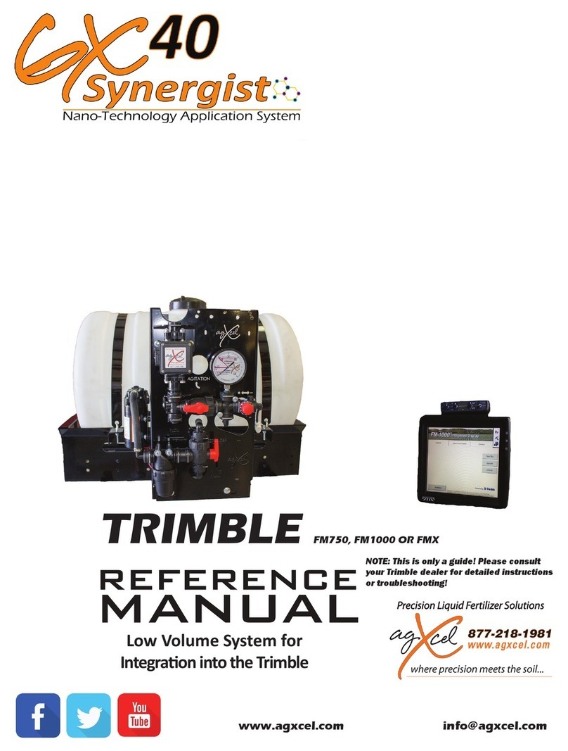
AgXcel Muller ISO User manual

PO Box 1611
Kearney, NE 68848
877.218.1981
www.agxcel.com REV81922
Quick Start Setup Instructions for Müller ISO
RCM - Single Product
PLEASE NOTE: Your setup may vary. Not all screens are shown. See
Müller Operator’s Manual for safety information and additional
setup/operating information.
Master Switch
•Master Switch to turn
on and off system when
physical Master Switch is
not enabled
Configuration
•Advance Settings
•Speed Settings
•Distance Measurements
•Section Configuration
•Diagnostics
Tank
•Refilling Tank
•Emptying Tank
Rate Adjustment
•Rate Target
Selection
•Auto/Manual
•Rate Increase/
Decrease
Road Mode
•Road Mode function is
used for safe transport
on public roads
Next Page
•Displays
further function
icons
Counters
•This opens a screen
with counters.
Sections
•Opening and
closing section
valves from left
to right or from
right to left
Müller-Elektronik’ technology is a very flexible control platform with many capabilities. This quick start setup guide will show you
the necessary steps to setup your display to control AgXcel’ s Fertilizer Pump Systems. Follow the general directions in your Müller's
User Manual (especially under Configuration and Liquid Rate Control). This manual will show you the specific numbersand settings
to use with your AgXcel Fertilizer Pump System.
MENU STRUCTURE FOR LIQUID RATE CONTROLLER
On the Next Page…
System Information
Virtual Terminal (VT)
When your Müller ISO Liquid Rate Controller is correctly connected, it will be discoverable in your monitor's Virtual Terminal
section. Select the Virtual Terminal icon, which can be in different areas of the controller.
•From the “Home” screen, press the “VT” or “ISO” icon on the bottom of the screen, which will take you to the Virtual
Terminal screen.
•Once on the Virtual Terminal screen, your Müller ISO module will be detected. Once detected, it will load your current
configurations. If this is your first time setting up, it will display a message letting you know that system has not been
configured.
AGXCEL, LLC

WWW.AGXCEL.COM 877-218-1981 info@agxcel.com
Page | 2
Quick Start Setup Instructions for Müller RCM ISO -
Single Product
(Configuration Icon)
(Advanced Configuration Icon)
•Enter the following settings in:
Number of Products: 1
Number of Booms: 1
Product 1 Control Type: PWM
Bypass: Unchecked
Tank Control: Unchecked
(Next Page Icon)
TC Machine Description: This setting is user preference.
(If unsure, leave it set to default Auto.)
Maximum Speed: This setting is user preference.
(This value is the max speed that the control system will
operate and will trigger “Road Mode” if you exceed it)
Snap to Rate: 10%
Simulation:Unchecked
(Placing a checkmark on "Simulation” puts the ECU for demo
purposes)
SYSTEM CONFIGURATION
System configuration is where you will set the Müller ISO to be compatible with the AgXcel fertilizer system. AgXcel has found
the best settings to work with their fertilizer pump systems. Please carefully follow each step to set up your controller.
Setting up for Single Product
•Locate your Müller ISO system password located in your
user manual. This password is used to unlock the
Advanced Configuration settings. If you cannot locate it,
please contact your Müller dealer.
•From the Home screen, press the Configuration icon.
•You will then be able to see the locked Advanced
Configuration icon.
•Once pressed, the screen will display the area to insert
your password
Advance Configuration (Features)
•Once done, press the 3-dot icon to go
to the next page of the Advance
Configuration.
AGXCEL, LLC

WWW.AGXCEL.COM 877-218-1981 info@agxcel.com
Page | 3
Quick Start Setup Instructions for Müller RCM ISO -
Single Product
Product 1 Master/Dump Valve:No Master/Dump Valve
(When Dump Valve is selected, the valve will remain open
when not applying)
Boost Pump: Unchecked
(Put a checkmark if the system is setup for use of a booster
pump)
Control PWM Base Freq:
GX5 (hydraulic)… 150 Hz
GX2 (electric)…….150 Hz
GX40 Synergist….150 Hz
*These settings are adjusted as needed.
P: This is a portion of the loop that is proportional to the amount of time the error is present
I: This is the portion of the loop that accumulates previous errors. It is the “memory” of the control loop. For each loop cycle, the
integrator adds the current error to the previous integrator value.
Dead Band: The allowable value that NO controlling/corrections will be made to the control valve. A low number may result in
oscillation around the target rate. High number may result in not achieving the target rate.
Minimum/Maximum Time: Min/ms is the value the output will start from no matter how much correction is needed. Max/ms is
the max value the output will reach once saturation of the output has been reached
•Press the 3-dot icon to go to the next page of the
Advance Configuration.
Advance Configuration (Features) Continued
•Press the 3-dot icon to go to the next page of the
Advance Configuration.
Product 1 Controller Settings*:
P:
GX5 (hydraulic)…. 3.0
GX2 (electric)……. 3.0
GX40 Synergist…. 3.0
D:
GX5 (hydraulic)… 0.5
GX2 (electric)……. 0.5
GX40 Synergist…. 0.5
PWM Min:
GX5 (hydraulic)… 10%
GX2 (electric)……. 10%
GX40 Synergist…. 10%
I:
GX5 (hydraulic)…. 3.0
GX2 (electric)……. 3.0
GX40 Synergist…. 3.0
Dead Band:
GX5 (hydraulic)… 3%
GX2 (electric)……. 0.0
GX40 Synergist…. 0.0
PWM Max:
GX5 (hydraulic)… 100%
GX2 (electric)……. 100%
GX40 Synergist…. 100%
AGXCEL, LLC

WWW.AGXCEL.COM 877-218-1981 info@agxcel.com
Page | 4
Quick Start Setup Instructions for Müller RCM ISO -
Single Product
•Enter the following settings in:
Application Type: Liquid Fertilizer (gal)
Target Rate: User Preference
Delta Target Rate: User Preference
Delta Target Rate: This number reflects the amount of change to
the rate each time Delta Target Rate is increased or decreased is
pressed
(Next Page Icon)
(Back Icon)
•Enter the following settings in:
Tank Size: User Preference
Meter Cal: Please see Chart below
Pressure Sensor*: If a pressure sensor is installed, please
select “Analog” option. If an electric pressure sensor is not
installed, please select “Not Installed” option.
*When using AgXcel’s optional Pressure Transducer Kit PN 53491
(Next Page Icon)
•Once completed, Press the Back Icon
to return to the Configuration screen.
Configuration 1/4
Configuration 2/4
•Once done, press the 3-dot icon to go to
the next page of the Advance
Configuration.
•Once done, press the 3-dot icon to go to
the next page of the Advance
Configuration.
Orion Magnetic Flow Meter Calibration Numbers
AGXCEL, LLC

WWW.AGXCEL.COM 877-218-1981 info@agxcel.com
Page | 5
Quick Start Setup Instructions for Müller RCM ISO -
Single Product
•Enter the following settings in:
Working Width: This would be the total width of the implement
Ext. Master Switch: User Preference. If Master Switch is not
present, select None.
(If an External Master Switch is selected, the onscreen master softkey
will be removed. Choose the option for your setup from the pop-up
screen:
Momentary Switch, Latching (Low=in work), Latching (High=in work)
Configuration 3/4
Product 1 Reg. Factor:
GX5 (hydraulic)… 10
GX2 (electric)……. 10
GX40 Synergist…. 10
Min Rate Control Speed
GX5 (hydraulic)… 0.5
GX2 (electric)……. 0.5
GX40 Synergist…. 0.5
Minimum Speed
GX5 (hydraulic)… 0.5
GX2 (electric)……. 0.5
GX40 Synergist…. 0.5
Configuration 4/4
•Enter the following settings in:
Lock at Last: Unchecked
(Lock at Last setting should be checked if you want to keep the pump
running while the planter is up. This allows for quicker return to the
Target Rate when you start applying again. Only use this if you have a
return line back to the tank. This can cause high pressure if no return is
plumbed. Warning: If Lock at Last is enabled and there is no return line
plumbed, flow will not be able to stop. The Master Switch will not have
the ability to turn off product flow.)
Jump Start: Unchecked
(Check the Jump Start feature if you want to start applying before the
implement is up to speed. Enter the speed that corresponds to the rate
you want to apply at when pressing the Jump Start button. Enter the
amount of time in seconds you want Jump Start to control the
application rate while tractor achieves the desired speed. This option
allows operator to start applying from a stop position and allow tractor to
get up to operating speed.)
Work Switch: User Preference. If Work Switch is not present,
select None
(To setup the Work Switch, press the selectable area.. Choose the option
for your setup from the pop-up screen:
Latching (Low=in work), Latching (High=in work), ISOBUS Tractor, Case
IH Planter Status
)
AGXCEL, LLC

WWW.AGXCEL.COM 877-218-1981 info@agxcel.com
Page | 6
Quick Start Setup Instructions for Müller RCM ISO -
Single Product
(Configuration Icon)
(Section Configuration Icon)
Open or close the section valves
from left to right or from right to
left.
Open or close the section valves if
you have 4 sections or less
`
SECTIONS CONFIGURATION
A section refers to a part of the implement in which all the nozzles are supplied with liquid from a section valve. Closing the
section valve switches off the section. The implement has as many sections as it has section valves which can be switched off. The
first section is always on the left in the direction of travel. The second is on its right.
Entering the Number of Sections
•From the Run Screen, press
the Configuration icon
•Then press the Sections
Configuration icon
•The Sections screen will appear (shown on right). If
the section number is unchecked, the system will
disable the specific section, and it can’t turn on from
the Run Screen. This feature allows the operator to
disable the sections that aren’t going to be used.
•Enter the number of sections in the Total Sections
field.
•Enter the number of rows in each section.
•Fence Rows: None
•Press the back icon
*Note: The ECU will indicate that it needs to be
restarted. You can restart the system now that you are
at the conclusion of the set-up process.
*Note: Please note with using AgXcel’s
integration Harness PN 56410 the following
configurations are possible:
1 Product Configuration: Have up to 8 Sections
2 Product Configuration: Have up to 6 Sections
Icons for Sections on Run Screen:
AGXCEL, LLC

WWW.AGXCEL.COM 877-218-1981 info@agxcel.com
Page | 7
Quick Start Setup Instructions for Müller RCM ISO -
Single Product
(Alarms Icon)
(Tank Filling Icon)
Product Rate Alarm: Checking this value will activate
an alarm to alert the operator if application is outside
of the specified Target Rate.
Allowable Error: Adjusting this value sets the
percentage of Target Rate error before the operator
receives a warning.
Tank Level Alarm: Checking this value will activate an
alarm to alert the operator when the tank level is low.
No/Low Flow Alarm: Checking this value will activate an
alarm to alert the operator when the Actual Rate is greater
than 25% of the Target Rate. If the system has a dump valve,
this feature can protect the pump and keep it from burning
up.
Entering the Fill Amount in the Tank
You must input the amount of product in your tank
prior to starting to operate for the system to correctly
display tank content
Current Volume: This will display the current gallons
that are present in your tank. (Tank size is set up in
page 2 of configuration).
Fill Amount: This is the amount that will be added to
the tank level.
Max Tank Icon: Press when the tank
is completely full
Empty Tank Icon: Press when the
tank is completely empty.
•Press the Alarms
Icon on the side
•Press the Tank Filling
Icon on the side menu
ALARM CONFIGURATION
AGXCEL, LLC

WWW.AGXCEL.COM 877-218-1981 info@agxcel.com
Page | 8
Quick Start Setup Instructions for Müller RCM ISO -
Single Product
(Configuration Icon)
(Pressure Calibration Icon)
DIGITAL PRESSURE CONFIGURATION
If a pressure sensor is installed, please select “Analog” option on the configuration screen on page 4 of this guide. To adjust the
pressure sensor settings, press the Configuration Icon. Once pressed then press the Pressure Calibration button. Be sure to use
an accurate pressure gauge to compare the system against the pressure sensor. Pressure sensor settings are not available until
the Pressure Sensor Analog option is selected in the product set up.
•From the Run Screen, press
the Configuration icon
•Press the Pressure
Calibration icon
Pressure Sensor: Select the name of the product for the
Pressure Sensor
Offset: 0.00 v
(The offset setting allows adjustment to the voltage range.
The range can be increased or decreased).
Slope: 0.00 psi/V
(The Slope value shows psi/V for the pressure sensor. 1 volt =
20psi).
Current Pressure: This value is the current pressure reading
from the Pressure Sensor.
The AgXcel fertilizer application system can be configured with an optional pressure transducer feature. This optional kit will
allow the user to display pressure on screen in cab, However, pressure monitoring is an important tool in system setup and
system troubleshooting and can assist in ensuring that the liquid application system is operating properly, and this may be
attained with a standard analog gauge or a pressure transducer.
AgXcel’s Pressure Transducer Kit (Optional) – PN# 53491
AGXCEL, LLC

WWW.AGXCEL.COM 877-218-1981 info@agxcel.com
Page | 9
Quick Start Setup Instructions for Müller RCM ISO -
Single Product
(Configuration Icon)
(Flow Cal Icon)
•
Confirm the Calibration Method is set to Simple
Catch Calibration.
•Press the Play icon to begin the calibration for
Product 1 or Product 2.
•The Flow Calibration screen will appear.
•Enter the values for Target Pressure, Target
Rate, Target Speed, and Nozzle Spacing.
•Press the Play icon to proceed.
CALIBRATING FLOW METER – SIMPLE CATCH
The Simple Catch Calibration method allows the user to calibrate the flow meter without moving the vehicle. For safety reasons,
this method cannot be used when the product type is anhydrous. The simple catch test is completed in calibration screens and
done statically. The user starts application and catches flow from a single nozzle for 1 minute or a measured time interval. The
system converts the catch amount to a gal/min value and enters it in the calibration screens.
Because the number of pulses per gallon can change during the lifespan of a flow meter, calibration must be carried out in the
following cases:
Prior to initial startup
At the start of each session
If you notice that there are deviations between the actual
applied amount and the displayed amount
When you have exchanged or repaired the flow meter
•From the Run Screen, press
the Configuration icon
•Press the Flow Cal Icon. Once
pressed, the Flow Calibration
Screen will appear
AGXCEL, LLC

WWW.AGXCEL.COM 877-218-1981 info@agxcel.com
Page | 10
Quick Start Setup Instructions for Müller RCM ISO -
Single Product
(Master On/Off Icon)
`
CALIBRATING FLOW METER – SIMPLE CATCH CONTINUED
•The Flow Calibration Control screen appears
•Setup a container(s) on the implement to catch
the product that will be applied during the
calibration. Activate/Deactivate the sections you
want to apply during the catch test with the
section control icons.
•
Press the Master ON/OFF icon
to start application. Apply
product for 1 minute.
•Press the Master ON/OFF icon to stop
application.
•Enter the applied amount in gallons in the Actual
Amount line. Once this amount is entered, the
Meter Cal value will be updated. The user can
accept the updated value with by pressing the
check mark or press “X” to return to calibration
start screen without updating the Meter Cal
Value.
•Press the Back Arrow to exit the screen.
•You have now calibrated the flow meter.
AGXCEL, LLC

WWW.AGXCEL.COM 877-218-1981 info@agxcel.com
Page | 11
Quick Start Setup Instructions for Müller RCM ISO -
Single Product
AGXCEL LIQUID SYSTEM FREQUENTLY ASKED QUESTIONS (FAQ)
I am trying to achieve 5 GPA, but my system will not go lower than 9 GPA.
Make sure your PWM Low Limit is set to a number that is lower than your required lowest rate. This can be found in
your Valve Control PWM settings on your console. If the PWM Low Limit is set too high, you will not be able to achieve the lowest
rate possible if set other than 10. Many times, setting the Low Limit to 0 will work just fine especially when running lower rates.
With an AgXcel System always make sure your Minimum Flow rate is set to 0.0 GPM or your system will not drop
below this rate. For example, if the Minimum flow rate is set to 3 GPM your system will not drop below this setting so if your
required GPA needs 2.1 GPM then your system will not achieve this rate given that you have set the Minimum Flow rate to 3
GPM.
When using an AgXcel GX5 Hydraulic system, make sure the AgXcel silver hydraulic valve is NOT in manual override.
Check to ensure that the RED knob on top of the valve is pressed down by turning the knob clockwise while pressing the RED
knob down. This will lock the PWM valve down so that the electronic solenoid can control the hydraulic flow.
I am trying to achieve 12 GPA but my system will only go up to 8 GPA on my GX5 Hydraulic system or I am trying
to achieve 8GPA and can only achieve 5 GPA on my GX2 electric system
AgXcel GX2 Electric System
What is your system pressure? If system pressure is too high (50PSI or above) this will prevent you from achieving your
highest rate possible. High system pressure with an electric system can put the electric pump head into bypass mode and will not
allow for full flow.
Check the following areas to lower your pressure
Select a larger orifice or Micro Tube with a larger hole, this will allow for easier flow of liquid through the system
and can increase over all flow and GPA
Check your system filters and make sure they are clean. This should be a practice each morning before using
the system
AgXcel GX2 Electric Systems can achieve up to about 5.9 GPM with dual electric pumps. Check your total GPM
requirements and ensure that you are within range
When using a Dual Pump System – unplug 1 pump and ensure that the other pump is working. Perform this test with
both pumps and if one pump sounds weak replace it immediately
Ensure that your PWM High Limit is set to 100. Many times,
an Auto Tune will set this to a lower number so make sure
this is set to 100
If you controller has this option, make sure the PWM Duty Cycle is within range
Check all your boom widths and make sure that all are set correctly
AGXCEL, LLC

WWW.AGXCEL.COM 877-218-1981 info@agxcel.com
Page | 12
Quick Start Setup Instructions for Müller RCM ISO -
Single Product
AgXcel GX5 Hydraulic System
What is your system pressure? If system pressure is too high (90PSI or above) this will prevent you from achieving your
highest rate possible. High system pressure with a hydraulic system set 100 PSI bypass spike valve to open and you could begin to
lose volume
Check the following areas to lower your pressure
Select a larger orifice or Micro Tube with a larger hole, this will allow for easier flow of liquid through the
system and can increase over all flow and GPA
Check your system filters and make sure they are clean. This should be a practice each morning before using
the system
Check your total GPM requirements and ensure that you are within range of the GX5 hydraulic pump’s recommended
GPM
Ensure that your PWM High Limit is set to 100. Many times, an Auto Tune will set this to a lower number so make sure
this is set to 100
If you controller has this option, make sure the PWM Duty Cycle is within range
Check all your boom widths and make sure that all are set correctly
My rate is fluctuating and is almost locking in but is jumping around
Make sure that your Rate Smoothing is checked and set to 10. You can typically find this setting under your System
Controller settings. Rate Smoothing allows the system to lock into the rate if the rate is within 10% of the required rate. Many
times, liquid temperature can affect the performance of the system.
Make sure your pressure is enough to fully OPEN every check valve on the implement. A good rule of thumb is to
ensure that pressure is higher than 15 PSI when using 4lb, 5lb and especially 10lb check valves.
How do I know where my pressure should be?
AgXcel systems are not pressure based especially when they are controlled with a Liquid Rate Control Module.
HOWEVER, pressure can affect the performance of the system if the pressure is too low or too high. Many users feel that the
higher the pressure then the less chance they have to plug an orifice. Although this statement holds value it can also have a
major effect on system performance.
Low pressure – RECOMMENDED 15PSI is the lowest
Can affect the performance of the pump and may cause it to surge which affect the accuracy of your flow
AGXCEL LIQUID SYSTEM FREQUENTLY ASKED QUESTIONS (FAQ) CONTINUED
AGXCEL, LLC

WWW.AGXCEL.COM 877-218-1981 info@agxcel.com
Page | 13
Quick Start Setup Instructions for Müller RCM ISO -
Single Product
AGXCEL LIQUID SYSTEM FREQUENTLY ASKED QUESTIONS (FAQ) CONTINUED
Can affect the performance of your system check valves, not enough pressure and all your check valves may
not OPEN.
High Pressure – RECOMMENDED – GX2 Electric = 25PSI GX5 Hydraulic = 70PSI
Too high of pressure can also affect the performance of your system as this can cause too much restriction in
the manifold tubes and too much resistance will slow the rate down.
RULE OF THUMB FOR PRESSURE
AgXcel GX2 Electric systems = 15PSI – 25 PSI
AgXcel GX5 Hydraulic systems
▪Low Range = 15PSI – 40 PSI
▪Medium Range = 20PSI – 50PSI
▪High Range = 40PSI – 80PSI
For High-Speed Planters check out the AgXcel GX30i VRT Solution
How do I raise and lower my pressure when required?
If your pressure is too HIGH then increase the size of your orifice and or Micro Tube to a larger hole size.
If your pressure is too LOW then change the size of your orifice or Micro Tube to a smaller hole.
TIP - Many times the system may have difficulty priming, or if a flow meter has not detected flow and you
want the system to continue running so as to prime. Go to Diagnostics > Tests > Calibrate PWM Limits
1. Time for Auto Mode Testing
2. Once again, enter a Test Speed
3. Press the AUTO button
4. Ensure that the height switch is down or unchecked
5. Turn the Master ON
6. You can now monitor system flow vitals and ensure that all outlets of liquid are flowing
7. Once again, check sections if sections are being used
8. System testing is complete - Turn OFF the Master Switch
AgXcel System Performance Settings - To ensure the best performance of your AgXcel system especially at Start Up, setting the
PWM Start Up % can be fine-tuned. PWM Start Up % sends voltage to the pumps at the % that has been set. This can assist in the
priming cycle to get the pumps running quicker. Once the pumps jump up to the % set, then it will begin its cycle to lock into the
required target rate setting.
AGXCEL, LLC

PRODUCT 1
SECTIONS
01
02
03
04
05
06
07
08
09
10
11
12
13
14
15
16
42-PIN
CONNECTOR
01
02
03
04
05
06
07
08
09
10
11
12
13
14
15
16
17
18
19
20
21
22
23
24
25
26
27
28
29
30
31
32
33
34
35
36
37
PRESSURE SIGNAL
FLOWMETER 1
PRESSURE SIGNAL 2
SECTION 03
SECTION 04
SECTION 05
SECTION 06
VALVE GROUND
SECTION 01
SECTION 02
SECTION 03
SECTION 04
SECTION 05
SECTION 06
SECTION 07
SECTION 08
PRESSURE SIGNAL
VALVE POWER (15A)
PRODUCT 1
01
02
03
04
05
06
07
08
09
10
11
12
13
14
15
16
GROUND
SECTION 09
SECTION 10
SECTION 11
SECTION 12
CHANNEL 1 PWM (-)
CHANNEL 1 PWM (+)
FLOWMETER 1
FLOWMETER GROUND
PRESSURE SIGNAL
VALVE POWER (15A)
12V HIGH CURRENT
VALVE POWER (15A)
SECTION 01
CHANNEL 1 PWM (-)
CHANNEL 1 PWM (+)
AgXcel Müller
Integration Harness Dual Liquid Product
Agxcel #56410
320-587
Wire Size: 18 AWG
Length: 3ft
Version 1.0
Edited 7-22-2021
38
39
40
41
42
SECTION 01
SECTION 02
12V HIGH CURRENT
12V ELECTRONIC
ELECTRONIC GROUND
HIGH V GROUND
PRODUCT 2
SECTIONS
01
02
03
04
05
06
07
08
09
10
11
12
13
14
15
16
VALVE GROUND
SECTION 01
SECTION 02
SECTION 03
SECTION 04
SECTION 05
SECTION 06
SECTION 07
SECTION 08
PRESSURE SIGNAL
VALVE POWER (15A)
SECTION 09
SECTION 10
SECTION 11
SECTION 12
VALVE POWER (15A)
PRODUCT 2
01
02
03
04
05
06
07
08
09
10
11
12
13
14
15
16
GROUND
CHANNEL 2 PWM (-)
CHANNEL 2 PWM (+)
FLOWMETER 2
FLOWMETER GROUND
PRESSURE SIGNAL 2
VALVE POWER (15A)
SECTION 01
CHANNEL 2 PWM (-)
CHANNEL 2 PWM (+)
MASTER SWITCH
IMPLEMENT SPEED
FLOWMETER 2
IMPLEMENT SWITCH
A
B
C
IMP 5V
GND
IMP SWITCH
2
1
MSTR 5V
GND
MSTR SWITCH
5V POWER
5V POWER
5V POWER
SECTION 07
SECTION 08
AGXCEL, LLC

12
13
14
15
16
04
05
06
07
08
09
10
11
01
02
03
16-PIN TO
INTEGRATION HARNESS
GROUND
Servo (+) PWM
Servo (-) PWM
PRESSURE SIGNAL
FLOW GROUND
MASTER ON/OFF
POWER
FLOW SIGNAL
Agxcel #53697
309-506
Wire Size: 18G
Length: 10ft
AgXcel Channel Integration Harness
(PWM,Flowmeter,Pressure)
Version 1.1
Revised 08-15-22
PRESSURE
A
B
C
PRESSURE SIGNAL 1
POWER
FLOW GROUND
12V FLOW
A
B
C
FLOW SIGNAL
POWER
FLOW GROUND
MASTER ON/OFF
A
B
C
SIGNAL
POWER
GROUND
PWM
A
B
PWM (+)
PWM (-)
AGXCEL, LLC

16 PIN TO
6-SECTION
01
02
03
04
05
06
07
08
09
10
11
12
13
14
15
16
VALVE GROUND
SECTION 3
SECTION 2
SECTION 6
SECTION 5
SECTION 4
SECTION 7
SECTION 01
AgXcel 6-Section
Boom Harness
Agxcel #53594
309-504
Wire Size: 18 G
Length: 11 ft
Revised 1.2
Created 07-02-18
Updated 08-16-22
SECTION 8
SECTION 11
SECTION 10
SECTION 9
SECTION 12
PRESSURE
VALVE POWER
VALVE POWER SECTION 6
SIGNAL
+12V
A
B
C
PRESSURE
GROUND
+12V
SIGNAL
A
B
C
SECTION 5
+12V
A
B
C
SECTION 4
+12V
A
B
C
SECTION 3
SECTION 2
+12V
A
B
C
SECTION 1
+12V
A
B
C
+12V
A
B
C
SIGNAL
SIGNAL
SIGNAL
SIGNAL
SIGNAL
GROUND
GROUND
GROUND
GROUND
GROUND
GROUND
AGXCEL, LLC

16 PIN TO
12-SECTION
01
02
03
04
05
06
07
08
09
10
11
12
13
14
15
16
VALVE GROUND
SECTION 3
SECTION 2
SECTION 6
SECTION 5
SECTION 4
SECTION 7
SECTION 01
AgXcel 12-Section
Boom Harness
Agxcel #53800
309-507
Wire Size: 18 G
Length: 11 ft
Revised 1.2
Created 07-02-18
Updated 08-24-22
SECTION 8
SECTION 11
SECTION 10
SECTION 9
SECTION 12
PRESSURE
VALVE POWER
VALVE POWER
PRESSURE
GROUND
+12V
SIGNAL
A
B
C
SECTION 7
+12V
A
B
C
SECTION 6
+12V
A
B
C
SECTION 5
SECTION 4
+12V
A
B
C
SECTION 3
+12V
A
B
C
+12V
A
B
C
SIGNAL
SIGNAL
SIGNAL
SIGNAL
SIGNAL
GROUND
GROUND
GROUND
GROUND
GROUND
SECTION 8
+12V
A
B
CSIGNAL
GROUND
SECTION 9
+12V
A
B
CSIGNAL
GROUND
SECTION 10
+12V
A
B
CSIGNAL
GROUND
SECTION 11
+12V
A
B
CSIGNAL
GROUND
SECTION 12
+12V
A
B
CSIGNAL
GROUND
SECTION 1
+12V
A
B
CSIGNAL
GROUND
SECTION 2
+12V
A
B
CSIGNAL
GROUND
AGXCEL, LLC
Table of contents
Other AgXcel Farm Equipment manuals
Popular Farm Equipment manuals by other brands

Sulky
Sulky Polyvrac XT 100 VISION Technician's Operating Manual

Nedap
Nedap VP5001 instruction manual

SpeedEPart
SpeedEPart Agri-Fab 45-0175 owner's manual

Unverferth
Unverferth Killbros SeedVeyor 102 manual

AGI
AGI GRAINMAXX 6300 Series Assembly manual

Finn
Finn HydroSeeder T170 ML Operator Instructions And Parts Manual