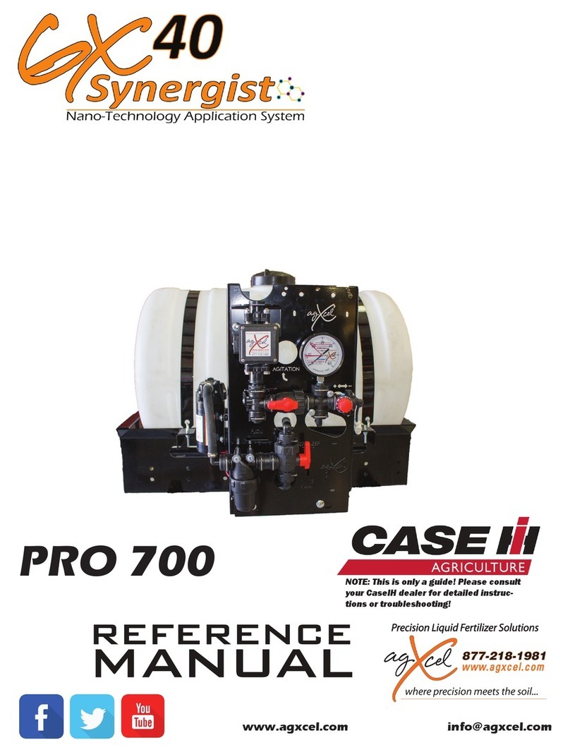
AgXcel Synergist GX40 System User manual

www.agxcel.com [email protected]
AUTOMATIC
RATE
CONTROLLER
reference
manual
Low Volume System for
Integraon into the Trimble
NOTE: This is only a guide! Please consult
your Trimble dealer for detailed instructions
or troubleshooting!
TRIMBLE
FM750, FM1000 OR FMX

www.agxcel.com [email protected]
2
Important Information
The AgXcel Synergist® system is designed for low volume distribuon of NutriSphere-N NH3 at a rate of 32
oz/acre. Higher rates are possible.
Note on ounces per acre
On the Trimble console display, the ow meter will be calibrated to measure this product in ounces, not gal-
lons. The display is programmed to show measurements in gallons, so be aware the numbers shown for this
product will actually be in ounces.
Ounces per acre means a very small amount of liquid is being distributed. At 6 mph on 30” spacing, 32 oz/
acre means that each row is doing just under 1 oz/min. On a 12 row implement the total amount being dis-
tributed is less than 12 oz/min. AgXcel’s Synergist system has been engineered to distribute this ow evenly
and accurately.
AgXcel’s Low Flow Magnetic Flow Meter
AgXcel’s Synergist system uses an electromagnec ow meter that is designed to accurately measure ow
on to 10 oz/min. With no moving parts this owmeter proves to be reliable, accurate, durable, and long
lasng.
Dual Micro tube Solution
AgXcel’s Synergist system uses our Dual Micro tube Soluon. Micro tubing eliminates the need for an
orice. By using a micro tube with an opening 4 to 5 mes larger than an orice, the risks of plugging are
greatly reduced.
By using a Dual Micro tube Soluon (two micro tubes), the system will be able to handle a variety of rates
and speeds. As well as handling a wide range of temperature changes that would aect the viscosity of the
product.
Floating Ball Manifold
Each row will be evenly distributed through a visual ow indicator with one or two oang balls. While pro-
viding a good indicaon of the ow to each row, they do not indicate the exact ow. AgXcel recommends
doing a catch test on each row to verify it’s distribuon.
Field Kit
The Synergist system has an oponal eld kit available (see pg. 29 for details) containing key replacement
parts for your system to reduce equipment downme.
Product and Rinse Tank
The Synergist comes with a 55 or 110 gallon product tank and 3 gallon rinse tank. The rinse tank can be
lled with RV an-freeze to allow the system to be ushed when not in use for a period of me, thus pro-
tecng the system from freezing aer rinsing.
AgXcel’s Micro Control Valves
Implements that are 60’ or wider can be split into 2 secons to allow secon control. Standard single
secon setups are equipped with AgXcel’s Micro Control Valve on each oang ball manifold. This allows
the system pump to connuously run when applicaon stops at the end of the eld to allow for a quicker
return to the target rate when applicaon resumes. A two secon system will have the same Micro Control
Valves but can be congured for two secons.

3
877.218.1981 [email protected]
Revised09.2018R1
Thank you for purchasing an AgXcel Precision Liquid Ferlizer Applicaon System (FAS) for your liquid
placement requirements. The AgXcel FAS system can be integrated into the following OEM controllers:
This integraon into these displays will require each of the OEM’s Liquid Control Module which will need to
be purchased from your local OEM dealer. The rate controller will provide the data required to manage the
speed of the AgXcel electric pump(s) based on the ow response of the ow meter and the vehicle speed.
The FAS system is also capable of managing secon controls, also referred to as swath control, to minimize
overlap areas with oponal secon control valves.
INITIAL INSTALLATION STEPS
AgXcel Fertilizer Application System Overview
(Read Instrucons Completely Before Beginning Installaon)
• Ag Leader
• John Deere Green Star
• Trimble
• Raven
• Top Con
• Outback
This guide contains informaon and sengs for AgXcel’s Synergist system for NutriSphere-N NH3. Changes to
components or conguraon sengs can be made to improve operaon of the system.
Below are some basic installaon steps.
• Have your control module and display in the cab connected and set up by your display dealer. To apply
anhydrous ammonia and NutriSphere-N NH3 you will need 2 rate control modules. One for the anhy-
drous ammonia and one for NutriSphere-N NH3, when using an Agxcel Integraon kit. However, when
using with the AgXcel AutoX Compact Plus, you only need 1 rate controller to control the NH3.
• Open and layout AgXcel’s Synergist and any components and familiarize yourself with system. See the
overview example for installaon ideas.
• Mount the AgXcel Synergist system on your equipment.
• Install and mount any oang ball manifolds, plumbing, and check valves to each row delivery unit.
• Aach any integraon harnesses.
• Apply sengs that you nd in this guide to your controller.
• Fill system with water and conduct ow and operaon tests.
• Winterize the system with RV an-freeze if freezing temperatures are expected.

www.agxcel.com [email protected]
4
AGXCEL INTEGRATION INTO THE TRIMBLE
System Overview - Example with GX40 Synergist
AgXcel Precision Ferlizer Applicaon Systems (FAS) are designed to integrate into various OEM controllers.
This installaon guide will assist in the controller conguraon sengs for the in-cab monitor. The integra-
on process begins with the users purchase and installaon of the corresponding OEM's Liquid Rate Control
Module.
The picture below displays the Trimble Rate Controller with the AgXcel integraon harnesses. Each Trimble
Rate Controller can control one product. Therefore, if you were applying two liquid ferlizers on you plant-
er, you will need three rate controllers, one for seed and two for liquid ferlizer. The harness coming out of
the Trimble rate controller is a 30 pin amp connector that will be connected to the AgXcel 30 pin cinch con-
nector extending from the AgXcel GX system.
Trimble Harness
F. AgXcel Control
Harness
(Connects to PWM)
PN#53697
C. AgXcel Integraon
Harness PN# 53519
D. Secon Valve
Harness
A. Trimble Rate and Secon Control Module
B. FM1000
C. AgXcel Integraon Harness - Part #53519
D. AgXcel Secon Valve Harness - Part #53594
E. MCV Harness PN# 54406
F. AgXcel Control Harness - PN#53697
G. AgXcel GX40 Synergist
In-line Check Valve
Feed to Shanks or other
applicators
Wilgers
3/8” Hose from owmeter to Micro
Valves then to manifolds
G.
B.
This harness connects to the AgXcel harness
(PN# 53697) PWM 16pin round connector for
pump control and the Agxcel secon control
harness. (PN#53594)
18 Pin Connector
• Connects to
Trimble Harness
back to in cab
display
E. Valve Harness
will connect into
the MCV harness or
Direct, depending
on rows & setup
A.

5
877.218.1981 [email protected]
Revised09.2018R1
AgX Integrate Into Trimble 03/26/12 December 24, 2012 8:39 AM Version 1.01
30
Pin
Connector
A B C D E F G H I J K
1
2
3
18
Pin
Connector
30
Pin
Connector
Trimble Rate and Section Control Module
18 Pin Connector
•Connects to Trimble Harness back
to in cab display
30 Pin Connector
•This harness connects to the AgXcel
integration harness P/N - 53519
Common Troubleshooting Guidelines:
PWM Signal to Pump: Pins E1 to E2 should have 0-12 volts to turn pump on.
Use manual mode to increase signal. Should get up to
12 volts after holding increase button.
Flow meter Tap Test: Pins C2 and C3 are Flow Ground and Signal. If no flow
is registering on the display, you can tap between these
two pins with a short wire. This produces a pulse. The
display should indicate a flow when this is done rapidly.
AGXCEL INTEGRATION INTO THE TRIMBLE
(Read Instructions Completely before Beginning Installation)

www.agxcel.com [email protected]
6
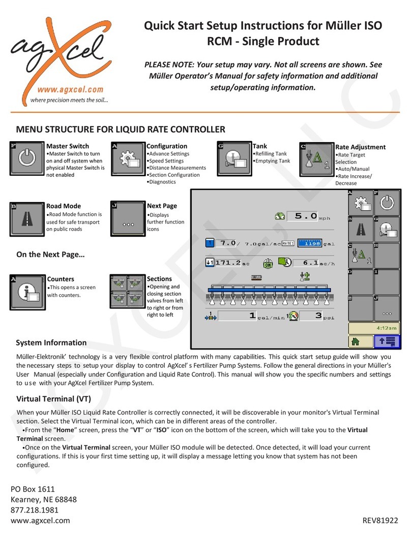
Quick Start Setup Instrucons for Trimble’s FM
750, FM1000, FMX Rate Controller
PO Box 1611
Kearney, NE 68848
877.218.1981
www.agxcel.com
PLEASE NOTE: Your setup may vary. Not all screens are shown. See Trimble’s Opera-
tor’s Manual for safety informaon and addional setup/operang informaon. Please
ensure you have the latest rmware installed!
MENU STRUCTURE FOR LIQUID RATE CONTROLLER
System Informaon
From the home screen, you can select 3 tabs; Support, Sys-
tem Informaon and Camera. The System Informaon tab is
shown above. This will show what Trimble components are
properly connected to your display. If your ferlizer system
quits funconing, rst check that the Control Module is sll
recognized on the display. If not, inspect the Trimble wiring
harness connecons or consult your Trimble dealer.
CFX-750 and FM750 Users
Informaon in this manual is applicable to the 750 except for
screen shots shown in the Setup & Operaon. The calibraon
and setup values in this secon DO apply to the 750. How-
ever, the 750 has a completely dierent screen layout and
menu structure that is not shown in this manual. Use your
Trimble manual to navigate, then enter the appropriate num-
bers from the AgXcel manual.
Conguraon – Setup & Calibrate
In the Setup & Calibrate menus, you will set the Trimble Field-IQ to work
properly with the AgXcel Ferlizer System. Carefully follow these steps to
rst make sure you have the proper sengs. Then, run the tests shown to
verify your ferlizer system is ready to go to the eld.
• From the home screen, choose Setup & Diagnoscs.
• The Conguraon screen below will appear. Choose Field-IQ. The Setup & Cali-
brate buons will be locked, shown by a padlock next to them.
• Push Setup, then enter “2009”
• Aer entering the code, the locks will disappear. Push Setup to proceed to the
next steps.
Home
• Support
• System Informaon
• Camera
Conguraon
• Setup
• Calibrate
• Diagnoscs
Cong Selecon
• Display
• Vehicle
• Implement
AGXCEL INTEGRATION INTO THE TRIMBLE
(Read Instructions Completely before Beginning Installation)
PLEASE NOTE: Your setup may vary. Not all screens are shown.
See Trimble’s Operator’s Manual for safety informaon and ad-
dional setup/operang informaon. Please ensure you have the
latest rmware installed!

7
877.218.1981 [email protected]
Revised09.2018R1
WWW.AGXCEL.COM 877-218-1981 info@agxcel.com
Quick Start Setup Instrucons for Trimble’s FM
750, FM1000, FMX Rate Controller
• Select Field-IQ and press the Setup buon.
• The next page will display 3 selecons, press the “Material Setup”
buon.
• Select one of the available material proles or press Add to add a
new material. Press Edit to change any of the parameters of the
material selected.
• Material Type will need to be set to Liquid.
• Give the material a name that makes sense.
• Set Target Rate 1 & Target Rate 2 as desired.
• Rate Increment increases or decreases your Target Rates by this
amount each me you press the rate Adjustment Switch on the Master Switch
Box.
• Manual Rate Increments work when the Rate Switch is in the Man-
ual Posion. This number controls the speed at which the valve
increases or decreases when you press the Rate Adjustment Switch
on the Master Switch Box.
• Minimum Rate is typically set at 0.
• Maximum Rate is set at something higher than the maximum rate
that will be applied.
These parameters may be adjusted as desired.
• Jump Start Speed is the speed the system will ramp up to when the
operator pushes the Jump Start buon on the Master Switch Box.
3.0 – 5.0 mph is a good seng for this.
• Jump Start Timeout allows the Jump Start Speed to run for a spe-
cic amount of me.
• Apply Latency to Boundary: set as needed so the system begins
applying when needed.
AgXcel recommends seng the Rate Snapping to On. This will smooth
out the rate uctuaon seen on the screen. If you are within the rate
smoothing range, the applied rate will just show your target rate and
not small deviaons from target rate.
Conguraon – Setup cont.
AGXCEL INTEGRATION INTO THE TRIMBLE
(Read Instructions Completely before Beginning Installation)

www.agxcel.com [email protected]
8
WWW.AGXCEL.COM 877-218-1981 info@agxcel.com
Quick Start Setup Instrucons for Trimble’s FM
750, FM1000, FMX Rate Controller
If this is your rst me seng up the Trimble Control, there will be
no Locaons entered. In that case, press Add and enter the informa-
on for a locaon. If there is a locaon and material that has been
created already, you can select and/or edit.
Setup - Control
Material
• Select your desired material from the Available Materials
Layout
• From the Layout screen, you can enter a Locaon Name such as Front Tank, Rear Tank, etc. If desired, you
can set up the Bin/Tank Setup to allow the system to track how much material is le in the tank.
• (OPTIONAL) If you would like to let your controller monitor how much material is le and set alarms when
the material is geng low, set your values in the Bin/Tank Setup.
AGXCEL INTEGRATION INTO THE TRIMBLE
(Read Instructions Completely before Beginning Installation)

9
877.218.1981 [email protected]
Revised09.2018R1
WWW.AGXCEL.COM 877-218-1981 info@agxcel.com
• If you have secon control set up on your liquid ferlizer system,
enable it by having the Secon Control set to On
• Press Setup next to Secon Control Module Locaon
Secon Control
• On the Secon Control Module Setup Screen, set the Number of Modules in your system.
• Select the Module’s Serial Number.
• Set the number of Secons for
your system.
• Press Secon Widths.
• Set the widths of your secons
• Press the Setup buon next to Secon Control to take you to the Secon Control Setup screen
• Set Secon Control Type to: “Boom Valve”
• Set O When Stopped to: “Yes”
• Press “Latency” buon to setup latency.
• On Latency: 0.50 s
• O Latency: 0.00 s
*Adjust these latency sengs as necessary in the eld.
Quick Start Setup Instrucons for Trimble’s FM
750, FM1000, FMX Rate Controller
AGXCEL INTEGRATION INTO THE TRIMBLE
(Read Instructions Completely before Beginning Installation)

www.agxcel.com [email protected]
10
WWW.AGXCEL.COM 877-218-1981 info@agxcel.com
Rate Control
• Select the Rate Control tab at the top of the screen.
• Set Rate Control to ON
• Set Number of Nozzles (number of rows)
• Set No/Low Flow Timeout to 45 s for troubleshoong so the system does not shut o too quickly.
• Press Setup next to Rate Control Module Locaon.
• Set the correct informaon on the Rate Control Module Setup screen.
• Press OK
• Trimble will take you back to the screen you see above. On Drive Setup, press Setup.
• Rate Control (Connued)
• Set up the Valve Setup as shown:
• Valve Type: PWM
• Valve Behavior When Secons Closed: Close
• Auxiliary Valve: Disabled
(OPTIONAL: If using an Aux/Dump valve to keep the pump run-
ning when applicaon stops so the system will resume applying at
the Target Rate immediately upon restart, set Auxiliary Valve to
Dump, then set Valve Behavior when Secons Closed to either
Lock in Last Posion or Lock at Minimum. This setup requires sec-
on valves with an addional dump valve plumbed to return ow
to the tank when applicaon stops.)
Press Feedback Setup buon on the
Drive Setup page.
Set the Feedback Setup as shown:
• Flow Meter Type: Other
• Flowmeter Calibraon: See AgXcel
Flow Meter Guide
• Minimum Flow: 0.0 GPM (Can be
set to the minimum specicaon
for the ow meter.)
Quick Start Setup Instrucons for Trimble’s FM
750, FM1000, FMX Rate Controller
AGXCEL INTEGRATION INTO THE TRIMBLE
(Read Instructions Completely before Beginning Installation)

11
877.218.1981 [email protected]
Revised09.2018R1
WWW.AGXCEL.COM 877-218-1981 info@agxcel.com
Select the Sensor tab
Set up the Sensor setup as shown
Sensor Type: Liquid Pressure
Name: Transducer (or other name)
Alarm: Enabled
Suggested Alarms:
Warn if Below:
GX5 (hydraulic)……………0
GX2 (electric)………………0
Synergist……………………..0
Warn if Above:
GX5 (hydraulic)……………80
GX2 (electric)………………25
Synergist……………………..35
Sensor Setup will take you to a screen where you can select
the Field-IQ Module that is controlling this sensor.
REMINDER: The pressure sensor is for informaonal purpos-
es only and does not control the system in any way.
To nish the Pressure Sensor setup, it will be necessary to go
to Field-IQ Calibraon and select Pressure Calibraon and
the name of the pressure sensor you set up.
Set the following as shown
Calibrate Type: Point/Slope
Slope: 50 mv/PSI
Flow Meter Guide
Pressure Sensor Setup
Quick Start Setup Instrucons for Trimble’s FM
750, FM1000, FMX Rate Controller
GX40 Synergist .... 35
GX40 Synergist .... 0
AGXCEL INTEGRATION INTO THE TRIMBLE
(Read Instructions Completely before Beginning Installation)

www.agxcel.com [email protected]
12
WWW.AGXCEL.COM 877-218-1981 info@agxcel.com
Implement Li Switch Calibraon
• From the Field-IQ Calibraon screen, select the Implement Li opon
• Raise the implement and then tap Next
• Lower the implement and then tap Next
• Tap OK to return to the Field-IQ Calibraon screen
Implement Setup
Implement Setup is where you set the informaon for the implement you
are using. Mainly these sengs aect the guidance control. However, if
using auto secon shuto, these sengs will determine when each secon
valve shuts o.
Measure your implement carefully and consult with your Trimble dealer for addional assistance with the
Implement Setup secon.
Quick Start Setup Instrucons for Trimble’s FM
750, FM1000, FMX Rate Controller
AGXCEL INTEGRATION INTO THE TRIMBLE
(Read Instructions Completely before Beginning Installation)

13
877.218.1981 [email protected]
Revised09.2018R1
WWW.AGXCEL.COM 877-218-1981 info@agxcel.com
• On the Calibraon page, select Field-IQ then
press Calibrate buon
• This will bring you to the Field-IQ Conguraon
screen
• Select Drive Calibraon
• You can leave Maximum Flow set to 0 or enter
the Maximum Flow rate of your pump in Gal/
Min. Then press Next
• Follow the screen instrucons to run Auto Tun-
ing procedure.
• Press Next at the boom of the screen to go to
the Drive Sengs.
• The sengs on the Drive Sengs screen are all
duplicated on the Advanced Parameters screen.
Press the Advanced Parameters buon to go to
the next screen.
• On the Advance Tuning page, set the sengs as
shown:
• Upper PWM Limit: 100
Lower PWM Limit:
GX5 (hydraulic)……………28
GX2 (electric)………………0
Synergist…………………….0
Integral Gain: (Adjust as needed)
GX5 (hydraulic)……………10
GX2 (electric)………………15
Synergist…………………….100
Minimum Response: (Adjust as needed)
GX5 (hydraulic)……………20%
GX2……………………………..0%
Synergist……………………..5%
Allowable Error:
GX5 (hydraulic)……………1%-3%
GX2……………………………..3%
Synergist……………………..5%
Smoothing Factor:
GX5 (hydraulic)……………1%-3%
GX2……………………………..3%
Synergist……………………..1%
Field IQ Calibraon
NOTE: The TMX-2050
will use Proporonal
Gain instead of the In-
tegral Gain. This is the
opposite of the FmX.
The Auto Tuning pro-
cess should set this. If
not, start with Propor-
onal Gain at 20-30.
Quick Start Setup Instrucons for Trimble’s FM
750, FM1000, FMX Rate Controller
GX40 Synergist .... 0
GX40 Synergist .... 100
GX40 Synergist .... 5%
GX40 Synergist .... 1%
AGXCEL INTEGRATION INTO THE TRIMBLE
(Read Instructions Completely before Beginning Installation)

www.agxcel.com [email protected]
14
AGXCEL INTEGRATION INTO THE TRIMBLE
(Read Instructions Completely before Beginning Installation)
WWW.AGXCEL.COM 877-218-1981 info@agxcel.com
Advance PWM Tab
1. Press the Advance PWM tab On the Field-IQ Drive Calibraon. Set the sengs as shown:
Base PWM Frequency ............ 100
Dither Frequency ....................... 0
Dither Amplitude ....................... 0
Dither Control:............... Absolute
Flow Calibraon
2. Select Field-IQ – Calibrate on the
Calibraon screen. This brings up the
screen where you can select Flow Cali-
braon.
3. The Flow Calibraon numbers may
have already been set in the
Drive Setup. You can verify or
update the sengs here.
4. Aer pressing “Run Calibraon”,
a screen that will allow you to in-
put your Target Rate and Speed.
Enter your typical applicaon rate
and eld speed. During calibraon, the system will run at the correct ow for this
rate speed.
5. You will need a stop watch to measure me. AgXcel recommends running the test
for some duraon in minutes for simple math. When your containers are in posion
under mulple ferlizer outlets, press the Start Flow, then turn
on the Field IQ master switch and start your mer. The system
will begin to run. When your containers are near full, push Stop
Flow.
6. Now you will need to measure the amount of liquid caught.
The number you enter must be in gallons per minute per row.
• Find total amount caught in ounces.
• Divide total ounces by number of rows caught.
• Divide ounces / row by 128 to convert to gallons /
row
7. Aer entering the amount caught, the Flow Calibraon
number will automacally change. If it has changed more
than 5%, review your catch test and repeat.
NOTE: AgXcel recommends running this procedure to verify set
up is completed correctly. We recommend changing the ow
calibraon back to the standard ion ow meter calibraon
shown on the ow calibraon on page 6.
Quick Start Setup Instrucons for Trimble’s FM
750, FM1000, FMX Rate Controller
11.

15
877.218.1981 [email protected]
Revised09.2018R1
WWW.AGXCEL.COM 877-218-1981 info@agxcel.com
Inial Operaon Instrucons
AgXcel highly recommends you perform these exact steps with water to verify system is correctly installed
and ready for eld use.
• From the Conguraon Screen, select Field-IQ, then Diagnoscs. (If the Diagnoscs tab is grayed out, you
probably need to close a Field)
• Make sure that your pump is ready to be tested. Raise the implement and then tap Next
• Press the + next to Speed to simulate a Speed signal.
• Turn the Field-IQ master switch (#5) On.
• Push each secon valve buon and verify each valve is
working.
• Turn Switch #2 to Manual and open the secon valves. Use
Switch #1 to increase ow. Does “Current Flow” display a
ow rate? Is it stable aer the system is primed? Do the
increase & decrease buons increase & decrease ow?
• Move Switch #2 to rate 1 and set speed to your typical
eld speed.
• The system should begin to pump liquid now in automac
control mode. Is the ow in GPM stable? Is it applying the
correct rate? (applied rate = target rate?)
• Change rate using screen buons or switch #1 to increase/
decrease rate or switch #2 to go to rate 2. Does applied
rate change to equal target?
• Close 1 secon valve, does ow decrease? Does applied
rate sll equal target rate?
• Change speed and target rate to minimum and maximum
values. Does the system perform at these values? Does the
system pressure seem reasonable (remember ferlizer will increase pressure over water)? Use “Sensor”
tab at the top of the page to read pressure sensor value (If equipped).
Running the System with water will create much lower pressure than ferlizer.
1 2 3 4 5
Quick Start Setup Instrucons for Trimble’s FM
750, FM1000, FMX Rate Controller
AGXCEL INTEGRATION INTO THE TRIMBLE
(Read Instructions Completely before Beginning Installation)

www.agxcel.com [email protected]
16
Pump Priming and Bleeder Valve
AgXcel’s Micro Control Valve
AgXcel’s micro control valves are designed to eliminate the need for
large seconal valves. The small compact design makes them ideal for
controlling ow through the manifolds.
Implements that are 60 and wider may be set up with 2 control valves,
therefore half of the applicator can be shut o. These systems are setup
similar to a single secon setup. However, Secon 1 of the boom harness
will connect to one valve and Secon 2 will connect to the other valve.
Please note, implements that are less than 60 feet wide need to be
setup as one secon on order to prevent range dropping below ow
meter capabilies at lower speeds.
A bleeder valve is included on every AgXcel system.
Every row has a check valve. These valves do not let
air escape from the system unless it is pressurized.
12 volt electric pump are not good air compressors,
so pumps can struggle to prime due to air trapped
on the outlet side of the pump.
The bleeder valve is a small 1/4” valve that, when
opened, lets air escape from the pump outlet at
zero pressure. Open this valve unl liquid comes
out and then close the valve.
Bleeder Valve
AgXcel’s micro control valve (MCV) includes an
indicator light. The red light shows voltage/power
being supplied to the valve. It will turn Green
when receiving a signal to open/close.
GX40 PRO STOP COMPLETE
REPLACEMENT BODY
PN# 709

17
877.218.1981 [email protected]
Revised09.2018R1
AgXcel’s Mag Flow Meter
0.08 - 1.6 GPM
AgXcel’s Magnec Flow Meters are superior to turbine ow
meters in two ways. Magnec ow meters have no moving
parts. This eliminates any wear items or any potenal for
contaminants to jam a spinning turbine.
In addion, magnec ow meters detect ow by electrically
measuring the velocity of the liquid which make them inde-
pendent of viscosity or density of the liquid measured. While
extremely accurate when using the indicated calibraon
number, AgXcel strongly recommends performing a catch
test to verify the system is properly installed and congured.
The ow meter included with your Synergist system is rated
down to 10 oz/min, but will accurately measure ow down
to 8 oz/min. Anything below 8 oz and the ow meter may
not give a connuous pulse output.
Cauon: Before welding on the implement, disconnect the
ow meter or damage to the ow meter electronics may
occur.
Do not power wash the ow meter. High pressure spray directed at the back edge of the face plate or at the
wire connector may allow water into the ow meter electronics.
Pressure Sensor
The GX40 Synergist comes equipped with a 100 psi pres-
sure sensor to work with your controller. The sensor for
the rate controller is a 3-wire type sensor. The Sensor has
a 1/4” MPT ng.
Your display will show the system pressure on the in cab
screen. The pressure reading is only for informaonal
purposes and is not used in the ow control process.
Flow control uses the owmeter feedback only.
The pressure sensor is very helpful to opmize system
performance and troubleshoot any issues.
The pressure transducer is factory calibrated and will
display a very accurate pressure reading on your display.
No manual gauge is required. However, the Synergist will
have a visual gauge for quick reference when standing
near the system and not in cab to see controller display.
When aaching connector to pressure sensor, make sure
pins are aligned so they are not bent.
396-2974Y1 SureFire
Catalyst™
for NutriSphere®-N NH3 & John Deere 7 Revised 03/16/2016
The Tower 100 comes equipped with a 100 psi pressure sensor to work with your controller.
This sensor for the John Deere Rate Controller is a 3-wire type sensor. The Commander II
uses a 2-wire sensor. The sensor has a 1/4” MPT fitting.
Your display will show the system pressure on the in cab screen.
The pressure reading is only for informational purposes and is NOT used in
the flow control process. Flow control uses the flowmeter feedback only.
The pressure sensor is very helpful to optimize system performance and
troubleshoot any issues.
The pressure transducer is factory calibrated and will display a very accurate
pressure reading on your display. No manual gauge is required.
When attaching connector to pressure sensor, make sure pins are aligned so they
are not bent.
Pressure Sensor
B
Components
Liquid
Pressure Sensor (3 wire
type) with harness
521-05-050150
Pump Priming and Air Bleed Valve
An air bleed valve is included with each pump to aid in system priming. It is shipped in the pump accessories
bag and must be installed during system installation.
Why use an air bleed valve:
Your system is equipped with a 4 lb. check valve
on each metering tube. These valves do not let air
escape from the system unless it is pressurized.
12 volt liquid pumps are not good air compressors.
Therefore, the pump can struggle to prime due to
air trapped on the outlet side of the pump.
The air bleed valve is a small 1/4” valve that when
opened lets air escape from the pump outlet at
zero pressure. Open until liquid comes out and
then close the valve.
How to install the air bleed valve:
Remove the 1/4” plug from the quick connect fitting
on the center cross on the Tower (see picture).
Next, insert the 1/4” tubing in the quick connect
fitting. Run the 1/4” tubing to an easily accessible
spot on your equipment. Next, cut the tubing and
push the 1/4” valve onto the tubing. Finally, run the
tubing to a low location where any product that
escapes will run on the ground.
Be sure the air bleed valve tube does not
become plugged with dirt or it will not allow air
to bleed.
1/4” Tubing 1/4” air bleed valve
3-wire sensor
Pressure Calibration:
50 mv/psi
Shipped
from factory
with plug
installed.
PN #53491

www.agxcel.com [email protected]
18
PWM Signal
To Pumps
Power Supply
Status LED Control Signal LED’s
The status LED on the PWM is a good indicator to determine if
there’s a problem with the system. It is especially helpful if you
are calling in for tech support.
TROUBLESHOOTING
(Read Instructions Completely before Beginning Installation)
EPD LED Signals
AgXcel has 2 styles for EPD’s. One of the models
has three lights and the other model has ve lights.
Ensure that you are looking at the correct diagram to
conrm the signals you are receiving.
The PWM’s take 12 volts for
power and will send that
voltage to the pumps to kick
on and o. If the pumps are
not turning on, then your
PWM might not be geng
12 volts or your pumps might
have gone bad.
EDP Status Lights
EDP Status Lights

19
877.218.1981 [email protected]
Revised09.2018R1
Pumps run for a few seconds then turn off
This symptom is due to the pumps drawing more current than the 40 amp limit of the EPD.
1. Unplug the EPD connector going to the baery for 2-3 seconds. Removing power from the EPD resets it.
2. Go to Diagnoscs, Secon Test to invesgate this issue.
3. In Secon Test, hold down “+” buon for a few seconds. A single tap of this buon produces a very
small change in signal to the valve, so you must hold it.
4. Increase the ow slowly, checking the “1,2,3” screen to see you ow in GPM. Find the approximate ow
where the EPD kicks out. If this is below the ow you need you will need to reduce system pressure by:
• Looking for any unintended restricons or plugged rows
• Increase orice size
• Reduce ground speed
• Reduce applicaon rate
Electric pumps will not turn on
Connect pumps directly to baery
1. Find the EPD (electric pump driver) shown at right.
Connect the two connectors (highlighted green,
shown on the right) to each other. This will bypass
the module and supply 12 volts directly to pumps.
2. Do the pumps run? If not, check the 40 amp fuse
on the EPD harness that is connected to the trac-
tor baery. Inspect harnesses and connecons.
Make sure wire colors match up. (white/white,
black/black)
3. If using a dual pump system, test each pump by
plugging one pump at a me directly to the bat-
tery.
PWM Signal
To Pumps
Power from
Baery
Inspect connections for burned out connectors.
Inspect all connecons for bent or burned out leads. Constantly running the system at a
high pressure or geng more than the required voltage (12v) can result in burned out
connecons causing the system to not work properly.
TROUBLESHOOTING
(Read Instructions Completely before Beginning Installation)

www.agxcel.com [email protected]
20
IMPLEMENT SWITCH
(Read Instructions Completely before Beginning Installation)
IMPLEMENT SWITCH KIT:
1. Run/Hold oponal connecons (If not using be sure to use
provided loop to close circuit)
• For use with a N.O. (normally open) whisker switch,
remove the dummy plug and connect to your run/hold
switch wires. A smaller gauge wire (18 AWG minimum)
may be used for this low current circuit.
• For use with a hall-eect sensor, remove the dummy plug
and aach the plug from your sensor.
Illustraon shown has a 3pin connector.
HOw IT wORKS
The Run/Hold circuit on the Auto-X simply requires a
switch to open and close to turn the fertilizer flow on or off.
Place the whisker switch on a 3 point arm or wheel frame
that changes angle as the implement is raised and lowered.
When the whisker arm is bent up (against the tool bar),
the switch is open. the Auto-X will be in
HOLD, not applying fertilizer.
When the whisker arm is straight (not touching the toolbar),
the switch will be closed. The Auto-X will be in RUN, applying fertilizer.
Whisker Run/Hold Switch
* The Whisker switch will work with many other controllers. However,
the polarity might be reversed from the positions described above.
Auto-X Accessories
Whisker Run/Hold Switch
132
whisker switch
when red lead is
connected to pole 1
and black lead is
connected to pole 2
pumps will run when
whisker is straight
when red lead is connected
to pole 1 and black lead is
connected to pole 3 pumps
will run when whisker is bent
* The Whisker switch will work with many other
controllers. However, the polarity might be
reversed from the posions described above.
HOW IT WORKS:
Place the whisker switch on a 3 point arm or wheel frame that changes angle as the
implement is raised and lowered. When the whisker arm is bent up (against the tool
bar), the switch is open placing the controller in HOLD, not applying ferlizer.
When the whisker arm is straight (not touching the tool bar), the switch will be
closed. The controller will be in RUN, applying ferlizer.
12
3
when red lead is connected
to pole 1 and black lead is
connected to pole 3 pumps
will run when whisker is bent
when red lead is
connected to pole
1 and black lead is
connected to pole
2 pumps will run
when whisker is
straight
GXIMPLEMENTSWITCH KIT
PN# 53824
PN# 53982 (2 PIN/JD STYLE)
KIT INCLUDES:
1- 15FT Extension (John Deere or 3pin connector)
1- Implement Switch with15FT Lead
1- Magnet Mount
EXTENSIONS AVAILABLE
3PIN 2PIN DESCRIPTION
17924 55917 GXH_EXT 15FT
54073 55415 GXH_EXT 30FT
*Custom extension lengths can be special
ordered - contact SALES for a price quote*
Other manuals for Synergist GX40 System
1
Table of contents
Other AgXcel Farm Equipment manuals
Popular Farm Equipment manuals by other brands

Pessl Instruments
Pessl Instruments METOS iMETOS WorkTrack user manual

FASTERHOLT
FASTERHOLT GT12 User manual & spare parts catalogue

Major
Major CONTOURA MJ76-360 Operator's manual and parts list

aivituvin
aivituvin AIR 70 instruction manual

Monosem
Monosem NG Plus 4 2018 Assembly and maintenance instructions

Green Frog Designs
Green Frog Designs Square Foot Garden Assemble