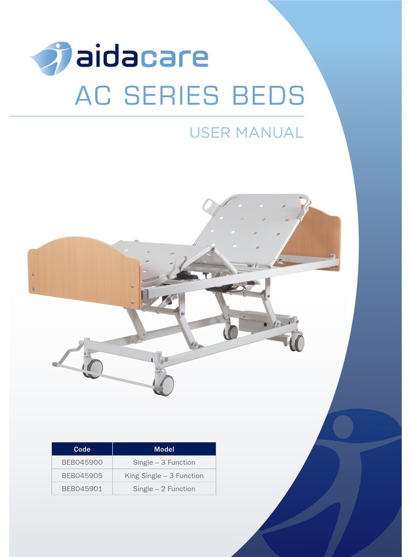
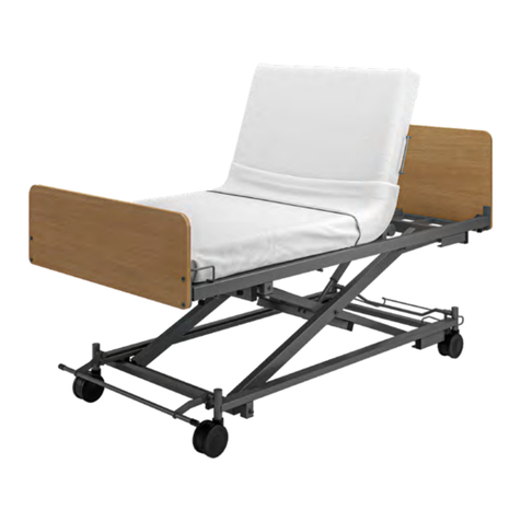
aidacare Ward Bed User manual

USER MANUAL
WARD BED
Designed to IEC60601-2
International Standards
1300 133 120
www.aidacare.com.au

2 3
www.aidacare.com.au
TABLE OF CONTENTS
1. Introduction
2. Safety Precautions
3. Electronic Functions
4. General Bed Operation
5. Specifications
6. Cleaning
7. Maintenance
8. Troubleshooting
9. Transportation and Storage
10. Accessories
11. Warranty and Service
4
5
7
11
17
18
19
21
22
22
23
Thank you for choosing this Aidacare
Ward Bed.
This product has been specifically designed to
oer comfort, support and safety.
It is important that you read this user
manual carefully before using your new bed.

4 5
www.aidacare.com.au
1. INTRODUCTION
The Aidacare Ward Bed is an electrically operated acute care bed. It has a range of
functions and positional movements that assist caregivers and provide for patient
comfort. Ease of use, functionality, serviceability and cleaning practicality are key
features of this bed. The Aidacare Ward Bed has a fabricated steel structure with
a powder coated finish. Plastic components are made from urethane, PP and POM
nylon, ABS and HDPE plastic.
Clinical Applications and Area of Use
The bed is appropriate for high dependency patients who pose a moving and
handling risk and or whose clinical condition requires that they are positioned with
minimal physical handling. Patients with a moderate amount of independence can, at
the carer’s discretion, use the controls to adjust their own position.
Aidacare Ward Bed Key Features
• Maximum safe working load (SWL) of 250kg.
• Electrically adjusted height range - 355-815mm. This height range will vary if castor
specification is changed
• 150mm diameter twin TENTE castors with central locking brakes and steering.
• Trendelenburg tilt (14°), reverse Trendelenburg tilt (14°) and includes an electronic
horizontal stop function.
• Four sectioned electrically operated steel mattress platform with independent
adjustment of backrest angle (77°), thigh section angle (35°).
• Auto Contour Positioning - Provides synchronised movement of the backrest and
knee positioning in one operation.
• Side rails are available (optional accessory). Select between traditional 3/4 length
folding or gas assisted split section style.
• Strong and durable ABS bed ends.
• Lighter total weight than many other brands reduces attendant exertion during
transportation.
2. SAFETY PRECAUTIONS
It is important that this User Manual is read in its entirety prior to operating the
bed. The manual is designed to ensure that users are equipped with the information
required to competently and responsibly operate the bed and its accessories.
It is recommended that the User Manual be kept in an easily assessable place for
quick reference. If required Aidacare product specialists can provide additional
training.
All warnings and cautions within this manual should be strictly adhered to. Failure to
do so could result in harm to the patient or operator.
Warnings highlighted throughout this manual identify possible hazards in procedures
or conditions, which if not followed correctly could result in serious injury or fatality.
Cautions highlighted throughout this manual identify possible hazards in procedures
or conditions, which if not followed correctly could result in equipment damage or
failure.
GENERAL
• Electrical equipment can be hazardous if used incorrectly.
• It is recommended that the bed be positioned at its lowest height when
unattended by caregivers to minimise the risk of patient injury from falls when
getting in and out of the bed.
• Residual current devices (RCD) are not supplied with the Aidacare Ward Bed.
Please consult with your Biomedical Engineer/advisor concerning RCD requirements.
• The safe working load of the Aidacare Ward Bed is 250Kg. This includes the mass
of the patient, mattress and any accessories fitted to the bed.
• The clinically qualified person responsible should consider the age, size and
condition of the patient before using the bed and its accessories.
• Side Rails must only be used with a mattress of the correct size which is approved
for use with the bed.
• The maximum suggested mattress thickness for the Aidacare Ward Bed is 170mm
to ensure side rail safety.
• If fitted with battery back-up, the batteries should be charged for 24 hours prior to
first use.

6 7
www.aidacare.com.au
• ALWAYS use the bed to support one patient only. The Aidacare Ward Bed is
intended for one person use and may become unstable if used incorrectly.
• ALWAYS use a mattress of the correct size and type. A range of suitable pressure
reducing and pressure relieving mattresses are available from Aidacare.
• ALWAYS ensure the power cable is disconnected from the bed before
transportation.
• ALWAYS ensure the bed is at a safe working height before moving the patient or
transporting the bed.
• ALWAYS apply the brakes when the bed is stationary.
• ALWAYS position the bed at its lowest height when unattended by caregivers to
minimise the risk of patient injury from falls when getting in and out of bed.
• ALWAYS ensure that all hospital lines and power cables are free from possible
entanglement with mechanical parts of the bed.
• ALWAYS ensure that attendant and patient limbs are free from potential
entrapment areas before operating any functions.
• DO NOT use electrically operated beds in the presence of flammable gases.
• DO NOT use electrically operated beds in operating theatres.
• DO NOT place the handset or power cord across the mattress surface of the bed.
When the bed is not connected to mains power always store the power cord within
the power cord fixtures fitted to the bed.
• DO NOT use accessories that are not designed, or approved for use with the
Aidacare Ward Bed.
3. ELECTRONIC FUNCTIONS
WARNING
• Ensure that the patient, caregivers and other equipment is not positioned to
become either trapped, or crushed during bed adjustment.
• Ensure that the coiled power lead is not stretched excessively.
• Ensure that the handset cable and electrical supply cable cannot become
entangled with moving parts of the bed.
• DISCONNECT the electrical power cable from the mains and store before
transporting the bed.
• If the power cable shows any sign of damage, replace immediately.
CAUTION
• Do not operate the bed controls for more than the control systems
prescribed duty cycle (i.e. 6 minutes during a 60 minute period).
The Aidacare Ward Bed is powered by four electric actuators, which are
controlled by the buttons on the handset. Adjustment occurs only when a
button is pressed. Adjustment will stop when the button is released, or the
movements selection reaches the end of its range of adjustment.
• The mattress frame height adjustment uses two actuators working in unison
or individually to generate vertical lift or to enable trendelenburg tilt.
• The backrest adjustment actuator includes an inbuilt manual quick release
CPR function as well as a disengaging spline drive that only uses force in
the push direction. This is to reduce the potential for crush injuries during
lowering.
• Knee raise actuator.

8 9
www.aidacare.com.au
3.1 HANDSET BUTTON OPERATION
3. ELECTRONIC FUNCTIONS (CONT.)
3.2 BACKREST ADJUSTMENT
To move the backrest up or down, press and hold the
appropriate button on the handset. The backrest can be
adjusted through a range of between 0° and 77°.
WARNING: Care should be taken whilst operating the backrest
function to ensure hands and fingers are away from potential
squeeze hazards.
3.3 MATTRESS PLATFORM HEIGHT ADJUSTMENT
To move the mattress platform up or down, press and hold the
appropriate button on the handset. The platform height can be
adjusted through a range of 355-815mm.
WARNING: It is recommended that the bed be positioned at its
lowest height when unattended by caregivers to minimise the
risk of patient injury from falls when getting in and out of the
bed.
3.4 KNEE POSITIONING ADJUSTMENT
To move the knee positioning section up and down, press and
hold the appropriate button on the handset. The knee section is
adjustable through a range of 0° to 35°.
3.5 AUTO CONTOUR POSITIONING
Auto Contour Positioning provides synchronised movement
of the backrest and knee positioning in one operation. The
position helps provide a more natural resting environment for
the patient.
Back Rest Up Back Rest Down
Main Lift Up Main Lift Down
Knee Break Up Knee Break Down
Auto Contour Up Auto Contour Down
Tilt – Anti Trend Tilt – Trend

10 11
www.aidacare.com.au
4.1 (A) REMOVABLE MATTRESS
PLATFORM PANELS
The bed has removable mattress platform panels for
easy cleaning and infection control management.
Removing Mattress Panels
Panels are easily removed, without tools, by releasing
the sprung tabs that wrap around under the frame. To refit panels, line up cutouts
with the under frame supports and push down until the sprung plates “click” into
place. Take care to ensure fingers are clear when refitting to avoid entrapment.
4.1 (B) OPTION: UNIVERSAL SIDE RAILS
Horizontal Universal Side Rails are available as an
optional accessory to assist with patient safety. They
have two positions, either fully raised or fully down.
When the side rail is raised to its full height position, it
will automatically lock in place with an audible click.
Fitting Universal Side Rails
NOTE: The rails are a left and right hand set and when fitted correctly fold down
towards the foot end of the bed.
1. Before fitting the rails unscrew the hand wheel to bring the locking clamp into an
open neutral position which will allow the rail to fit over the side rail of the bed.
3. ELECTRONIC FUNCTIONS (CONT.)
3.6 TILT POSITIONING
Trendelenburg/Reverse Trendelenburg
The tilt button allows the bed to be positioned in a foot or head
down tilt position. Tilt positioning achievable is between 0° and 14°
for both head and foot down tilting.
CAUTION: The Trendelenburg function should only be used under
professional supervision.
• In use the mattress platform may initially rise before tilting. The bed will
automatically adjust to ensure there is sucient clearance between the mattress
platform and the mechanical structure of the bed before tilting.
• When reversing the tilt angle of the bed with the tilt button remaining depressed,
the mattress platform will pause at horizontal for two seconds before continuing
on with its tilting movement.
3.7 BATTERY BACKUP FUNCTION (IF FITTED)
A battery backup system allows the electrically operated functions to be used for
short periods when the bed is disconnected from mains power. If fitted, the bed
switches between mains and battery power automatically.
The battery will oer 12 or more full function cycles before depletion, with one cycle
being a complete movement through range and back again. e.g. Head section lifting
up to full height and then lowering to fully flat again is 1 cycle.
The battery is lead-acid and should be charged regularly and not be allowed to
discharge fully. Fully discharging the battery will cause a reduction in battery life.
To charge the battery, connect the power cord to the mains supply. This should be
done as often as possible to maximise battery life. If the bed is not used for a long
period of time it is recommended that the batteries are charged in accordance with
the Transportation and Storage guidance.
WARNING: Do not expose the battery to open flame or immerse in liquid.
NOTE:
• Always leave the bed on charge for 24 hours before initial use to ensure battery is
fully charged.
• Always keep the bed plugged into a power source whenever possible. This will
ensure optimal battery lift and facilitate ongoing trickle charging.
• Bed adjustment will be slower when the power cord is unplugged and the bed is
powered from its batteries.
• Always store the power cable using the cord minder hooks at the head end of the
bed whenever it is not in use or during transportation.
4. GENERAL BED OPERATION
Closed Position Open Position

12 13
www.aidacare.com.au
2. With both hand wheels now unscrewed, lift the rail into position. It is important
that the rails are fitted to a specific position on the bed, which is indicated by the
disc on the top of the side rail. Position the rail over the disc and tighten the hand
wheel to the closed position.
Universal Side Rail Operation
The rails are either fully raised, or folded down closed. When the side rail is raised
to its full height position it will automatically lock in the positioning hole on the
rail clamp plate. The release/lock knob feature can be both visually and audibly
confirmed.
WARNING: Do not operate side rails when there is potential of entrapment or
crushing to the patient, caregivers, visitors and/or other equipment.
Side Rail Operation
To raise the side: Lift the top rail until the locating pin/knob automatically clicks into
its locked position at maximum height.
To lower the side: Hold the top rail near the foot end of
the bed (1) and gently pull out the red operating knob
(2) lowering the side towards the foot of the bed whilst
controlling the descent speed. As the side begins to be
lowered, the operating knob can be released.
WARNING: Care should be taken whilst operating the
side rails to ensure hands and fingers are kept away from
potential squeeze hazards. Side rails should only be used
after clinical assessment and within organisational policy
and guidelines.
1
2
4.1 (C) OPTION: DROP DOWN SPLIT SIDE RAILS
Optional drop down split side rails are available and have two positions, either fully
raised or fully down. When the side rail is raised to its full height position, it will
automatically lock in place. There is an audible “click” sound when the lock engages.
These side rails have been designed to comply with IEC60601-2-52.
Fitting Drop Down Split Side Rails
Split side rails are easy to fit and bolt directly into the underside of the bed frame. This
requires two bolts that are included with the rails and are easiest to fit with a 17mm
spanner or ratchet ring spanner. To remove the rails, lower partially for greater bolt
head access and unscrew each bolt.
WARNING: Do not operate side rails when there is potential of entrapment or
crushing to the patient, caregivers, visitors and/or other equipment.
NOTE: The rails are a left and right hand set that gently lower vertically when
activated.
1. The rails fit directly to the bed frame via two bolts for each rail section. Before
fitting the rails, locate the bolt hole pairs on the underside of the bed frame.
B. Bolt hole pairA. Foot end rail and mounting bracket

14 15
www.aidacare.com.au
4.2 MANUAL CARDIOPULMONARY RESUSCITATION (CPR) FUNCTION
A clearly marked emergency CPR release handle is located on both sides of the bed.
The manual release function returns the backrest to a level position quickly to facili-
tate urgent needs.
Emergency Lowering
To lower the backrest, pull up on the red CPR release handle. The lowering
movement is assisted by a gas damper, but CAUTION is required as the backrest
may lower quickly under patient weight.
WARNING: The backrest can fall quickly - keep hands clear to avoid entrapment.
4.3 CASTOR SYSTEM - BRAKES & STEERING
The Aidacare Ward Bed has a central locking and direction castor system that is
operated via foot pedals found at the foot end of the bed.
• With the pedals in the Red - Down Brake position, the brakes are applied to all
four castors of the bed simultaneously and the bed is immobilised.
• With the pedals in the Horizontal Free position, the brakes are released and the
bed can be moved in any direction.
• With the pedals in the Green - Down Steer/Track position, a single steering castor
at the head end of the bed is engaged to provide better control when pushing the
bed in a straight line.
• Push the bed from the foot end using the handles in the foot panel.
Central Lock Pedal Positions
CAUTION:
• Disconnect the bed power cord before moving the bed.
• Do not remove the power cord from the source by pulling on the cord.
• Do not use the beds side rails to manoeuvre the bed.
• Do not pull on the power cord, or handset cord to manoeuvre the bed.
• Always apply the brakes when the bed is in a stationary position.
2. Position the rail bracket directly over the bolt holes and fasten the bolts securely.
3. To remove the rails, lower partially for greater bolt head access and unfasten
each bolt completely.
Drop Down Split Side Rail Operation
To raise the side: Lift the top of the rail until the spring loaded lock mechanism
automatically clicks into its locked position at maximum height.
To lower the side: Hold the top of the rail near the middle (1) and gently pull forward
the rail release handle (2). As the rail begins to lower the handle can be released and
the rail can be gently lowered to its down position. The rails lower softly for added
safety.
WARNING: Care should be taken whilst operating the side rails to ensure hands and
fingers are kept away from potential squeeze hazards. Side rails should only be used
after clinical assessment and within organisational policy and guidelines.
21
D. Fasten bolts through bracket into
bed frame
C. Position rail brackets over bolt holes

16 17
www.aidacare.com.au
4.4 HEAD AND FOOT PANELS
The head and foot panels are easily removable from the bed allowing quick
access to the patient. There are no clamps or screws that are required for
removal.
Installation & Removal
To Install: Using two hands align the bottom tubes with the
corner sockets as shown in the diagram.
To Remove: Reverse the above process.
CAUTION: Always install and remove the head and foot
panels in line with Manual Handling Procedures and Policies.
4.5 CALF AND THIGH PANEL ADJUSTMENT (OPTIONAL)
The calf panel angle can be manually adjusted (when fitted) whenever the
thigh section of the mattress platform is raised.
The thigh section is adjustable through a range from 0° (flat position) to 35°
fully elevated. This can be achieved using either the beds handset or attendant
control panel (ACP). The calf panel is adjustable through a range of 0° to 25°.
To Raise: Using the mattress retainer handle, pull the calf panel up slowly to a
position slightly past the desired position. The calf panel struts will produce a
clicking sound as the spring loaded locking mechanisms travel past the range
of available lock positions. Once the desired position has been reached, gently
allow the calf panel to lower. The lock mechanisms will automatically find the
first available position.
To Lower: Use the mattress retainer handle to raise the calf panel to the top
of range, this will release the ratchet mechanism and allow it to return to a
flat position. Lower slowly and keep hands clear of the panel as it may lower
quickly under patient weight.
CAUTION: Ensure correct lifting methods are used when adjusting the calf
panel.
4.6 BED EXTENSION
The integrated bed extension can add an extra 195mm of length to the mattress
platform.
Moving Bed Extension From Closed/Standard Bed Position
1. The bed extension is held in position by two threaded hand wheels on either
side of the bed. Unscrew (anti clockwise) the hand wheels on both sides. It is
not necessary to remove the hand wheels completely, unscrewing them by
approximately 10mm of thread length will allow for the internal lock nut to travel
freely past the thread of the hand wheel.
2. With both hand wheels now unscrewed, gently pull with an even force on both
sides of the panel.
3. The panel will stop at its fully extended length.
4. Return the hand wheels back to their locked position.
To reposition the panel back to the closed/standard bed position use the same
technique as above.
WARNING: The bed extension is designed for use as
a bed extension only and is not meant to support the
body weight of a person sitting. The extra length of the
bed with extra load can also make the bed unstable
potentially resulting in injury to the user and patient.
5. SPECIFICATIONS
Overall Length 2195mm
Overall Length Base Extension Extended 2390mm
Mattress Surface Length - Between Panel Faces 2030mm
Bed Extension Length 195mm
Mattress Surface Length when Extended 2225mm
Overall Width 1020mm (inc side rails)
Deck Height Range – Tente Twin 150mm Castors 355 to 815mm
Trendelenburg Tilt 0 to 14º
Reverse Trendelenburg 0 to 14º
Backrest Angle Adjustment 0 to 77º
Knee Break Angle Adjustment 0 to 35º
Calf Positioning Angle Adjustment (if specified) 0 down to 25º
Dimensions

18 19
www.aidacare.com.au
Maximum Suggested Mattress Size W = 900 mm L = 2000 mm H = 170 mm
Without Side Rails Fitted 123 kg
With Side Rails Fitted 137 kg
Safe Working Load (SWL) 250kg
Mattress Size Dimensions
Product Weight (approximate)
6. CLEANING
Power In 1A max. At 230V ac 50Hz
Duty Rating Intermittent 10%, Max 2 min / 18 min
Electric Shock Protection Class 1 Type B
Liquid Ingress Protection IP54
Internally Powered Equipment (Battery
Backup Only)
2 x 12V Series Connected Batteries
Sealed, Rechargeable Lead/Acid Gel
1.2 amp hrs.
ELECTRICAL DATA (230V)
Standards
The Aidacare Ward Bed has been built to comply with International Standard
IEC 60601-2
WARNING: Before cleaning always disconnect the bed from the mains power source.
Note: It is strongly recommended that protective clothing be used when cleaning.
Note: The following procedure also applies to the beds accessories, but does not
include mattresses.
• Wipe surfaces with a soft cloth moistened with hot water and mild detergent (or
the hospital’s recommended cleaning solution). It is recommended that the cloth
be a white material to prevent bleeding of die colours to the bed. Take extra care in
areas that can harbour dirt or dust.
• Rinse with clean water and a dry clean cloth.
• To remove potentially infectious materials such as body fluids, or when the bed has
been used by someone with a known infection. Clean with NaDCC (e.g. Presept,
Actichlor) at 10,000 ppm of available chlorine. Rinse and dry.
• Allow the cleaned parts to dry before replacing the mattress.
CAUTION: Do not use abrasive Hypocarbonate or Phenolic compounds or pads.
7. MAINTENANCE
To prolong the working life of the bed and for trouble free operation it is
recommended that routine inspections should be performed by a person who is
suitably qualified and well acquainted with the design, use and care of Ward beds.
If inspection reveals that the safety of the bed is jeopardised in any way, it should be
IMMEDIATELY WITHDRAWN FROM SERVICE, tagged as such and the owner notified.
The following preventative maintenance procedures should be carried out every 12
months.
Electrical test & tag – where beds are in use in a commercial environment then the
testing regime applied should align with the risk assessment made by the owner for
safety and other compliance requirements.
NOTE: Other than general maintenance activities all other service or repair work must
be performed by qualified and trained persons who are approved by Aidacare.
WARNING: The bed must be disconnected from the mains power supply before
starting any maintenance activity.
General
1Examine the bed for obvious signs of damage. All aspects of the equipment should operate as
intended. Check that all nuts, bolts and other fasteners are tight and are not missing.
2Examine flexible cables and conduits for cuts, cracks, abrasions or other deterioration.
3Check that the power supply plug is not damaged. If either the power cable or plug is damaged
then both the cable and plug must be replaced as a complete assembly by an approved service
agent.
Central Locking System
1Apply the brakes and push the bed forwards. If any of the four braking castors rotate the brake is
not fully effective.
2Check the two steering lock castors for correct operation.
3If either the brakes or the steering locks are not working correctly contact an approved service
agent.
Side Rails
1• Inspect the side rails for general wear and tear on fittings and pivot joints every six months.
• The locking pin mechanism and striker plate assembly should be checked every three
months.
• Check for rust, structural integrity of welds and paint finish every twelve months.

20 21
www.aidacare.com.au
2Raise the side rail to the upright position until the locking mechanism clicks into place. Refer to
the operating procedures for further instruction.
3Check that there is no yellow shaft visible. In the locked position the red on the locking pin shaft
should not be visible from above
4If the red shaft is visible when the side rail is in the raised and locked position, contact Aidacare
for service advice.
5Check that the rails pivot axles are securely fitted to the bed. The pivot axles are locked into
place by the manufacturer by a 10mm lock nut.
Patient/Nurse Handset Checks
Nurse/Attendant Control Panel
Aidacare strongly advises that the Handset is visually inspected for obvious damage before each use
if practicable. When using a specific function staff should be aware of, and checking for, any of the
symptoms listed in point 3 below.
Preventative Maintenance Checks
Aidacare recommends that the full check and testing regime is conducted between each bed use, or
worst case during annual preventative maintenance.
1
Visual Inspection of Control Panel & Handset Casing
1.1 Inspect the outer plastic casing for any obvious cracks or damage.
1.2 Inspect for damage to the front cover (outer label) particularly over the buttons where the
label may be torn or indented.
If any damage is identified while conducting checks 1.1 and 1.2, immediately lock out the
handset using the ACP and report the damage to maintenance staff or replace the Handset.
2
Visual inspection of the cable and cable insulation
2.1 Inspect the cable for any nicks or cuts in the insulation
2.2 Inspect for any evidence that the cable may have been squashed/flattened.
Squashed or flattened cables may indicate a possible break in the internal conductors or
insulation causing conductors to short together which could cause unwanted movement of the
bed. Any handsets that are found with obvious damage to the cable insulation immediately
report the damage to maintenance staff for handset repair or replacement.
3
Tactile inspection of the buttons:
All buttons should be operated and response tested.
Depress each button on the handset. Each button should have a positive audible click that is
also felt. If the function being pressed has any of the following:-
• does not have a click feel
• does not have an audible click sound
• does not immediately operate the function
• feels soft offering no resistance
• feels different to the rest of the buttons
• travels further when depressed
Immediately report the damage to maintenance staff or replace the Handset.
8. TROUBLESHOOTING
Symptom Possible Cause Action
All actuators fail to work Power diconnected or
batteries discharged
Ensure mains supply lead
is connected
Control box and handset
plugs disconnected
Check the plugs are fully
inserted in the control
box. Check that plugs
are fully inserted in the
sockets on the deck
frame.
Blown fuse Contact Aidacare Service
Department.
Damaged handset cable Replace handset
One actuator fails to work Actuator plug
disconnected
Check that actuator plug is
fully inserted in control box
Main Lift Actuators fail
to work and an audible
beeping sound can be
heard when handset is
activated
Control box requires
calibrating possibly due
to bed being operated
when batteries were fully
discharged
Ensure mains power lead
is connected and carry
out calibration procedure.
Brakes or steering lock
not eective
Wear or damage Adjust or replace castor
Backrest CPR release not
eective
Release mechanism not
correctly adjusted
Check and re-adjust

22 23
www.aidacare.com.au
9. TRANSPORTATION & STORAGE
The Aidacare Ward Bed should be stored in a clean, dry well ventilated area. Do not drop and avoid shock or
violent impact when transporting.
The following limits apply during transport and or a storage period of up to 15 weeks duration:
Ambient temperature -15ºC to +60ºC
Relative humidity 10% to 75%
Air pressure 50 kPa to 106 kPa
The following limits apply to normal operating conditions and or periods of storage longer than 15 weeks:
Ambient temperature +10ºC to +40ºC
Relative humidity 30% to 75%
Air pressure 70 kPa to 106 kPa
When storing the bed, or when the bed is not in use for prolonged periods of time it is recommended that the beds
battery system be maintained periodically using the following guidelines:
Storage Temperature Charging Interval
20ºC or less Charge batteries for 24 hours every 9 months.
20 to 30°C Charge batteries for 24 hours every 6 months.
30 to 40°C Charge batteries for 24 hours every 3 months.
A range of Ward Bed accessories are available. In addition to the below listed accessories, Aidacare specialises in
other complimentary products such as foam mattresses, pressure care surfaces, over bed tables, side lockers
and adjustable day chairs.
Please contact Customer Service on 1300 133 120 for further information.
Code Description
BEA029810 Split Side Rails with Gas Assisted Lowering
BEA029700 3/4 Length Folding Universal Side Rails
BEA029705 Self Help Pole – Stainless Steel
BEA029710 IV Pole – Stainless Steel
BEA029815 Beech Head and Foot Boards
BEA029820 Oxygen Bottle Holder – C Size
WARNING: Do not use accessories that have not been designed for use with the Aidacare Ward Bed.
10. ACCESSORIES
11. WARRANTY & SERVICE
Aidacare Ward beds carry a comprehensive warranty as detailed below. Please keep
proof of purchase for proof of warranty commencement.
Warranty Duration:
– Frame: 10 Years
– Electronics: 3 Years
– Handsets and Cable: 1 year
Consumer Warranty Against Defects:
Aidacare is bound by Australian Consumer Law in respect to Warranty Against Defects.
A copy of the Aidacare Warranty Against Defects statement is available on the Aidacare
homepage at www.aidacare.com.au. All warranty matters should be directed to Aidacare
Customer Service on 1300 133 120.
Aidacare does not warrant against excessive or incorrect use, modification or
any situation that could not be deemed as fair wear and tear. This is a back to base
warranty and does not cover freight costs pertaining to the return of any items under
warranty. Aidacare acknowledges and conforms to all ACCC guidelines around consumer
rights. For further information contact Aidacare on
Aidacare will not warrant the safety and or correct functioning of products where any
original components have been changed or modified by non-Aidacare approved and
trained service & maintenance sta or external providers. Furthermore, safety is not
guaranteed where components have been replaced with non-original Aidacare approved
parts. If any faults are detected upon receipt of this product please phone Aidacare. Any
faults that are detected during normal use should be reported to Aidacare immediately
to determine if warranty conditions apply and if so, the necessary repair or replacement
work to be completed.
Spare parts list is available upon request.
For servicing, preventative maintenance and any other questions regarding this or any
other Aidacare product please contact:
Aidacare Pty Ltd
4 Noonan Rd, Ingleburn NSW 2565
T – 1300 133 120
W – www.aidacare.com.au

AIDACARE PTY LTD
4 Noonan Road, Ingleburn NSW 2565
1300 133 120
www.aidacare.com.au
Table of contents
Other aidacare Medical Equipment manuals
Popular Medical Equipment manuals by other brands

ResMed
ResMed lumis series user guide

Moller Medical
Moller Medical LiquoGuard 7 manual

CSZ
CSZ Blanketrol III 233 Operation and technical manual

Access Sensor Technologies
Access Sensor Technologies UPAS v2 user manual

Otto Bock
Otto Bock 3F1-1 Instructions for use

Roland
Roland DWX-50 Setup & maintenance guide