4 5
aidacare.com.au
INTRODUCTIONSYMBOLS USED IN THIS MANUAL
The Aidacare FL250 Bed is an electrically operated Floorline Bed offering
functions and positional movements that assist caregivers and maximise
patient comfort and safety. Ease of use, functionality, serviceability and cleaning
practicality are key features of the bed. The bed has a robotically welded steel
structure with a leading anti corrosion treatment layer underlying the durable
powder coated finish. The plastic components are made from urethane,
PP and POM nylon and ABS plastic.
CLINICAL APPLICATIONS AND AREA OF USE
This bed is appropriate for adult patient care and should only be used under the
instruction of a carer or health professional where concerns exist around patient
safe use.
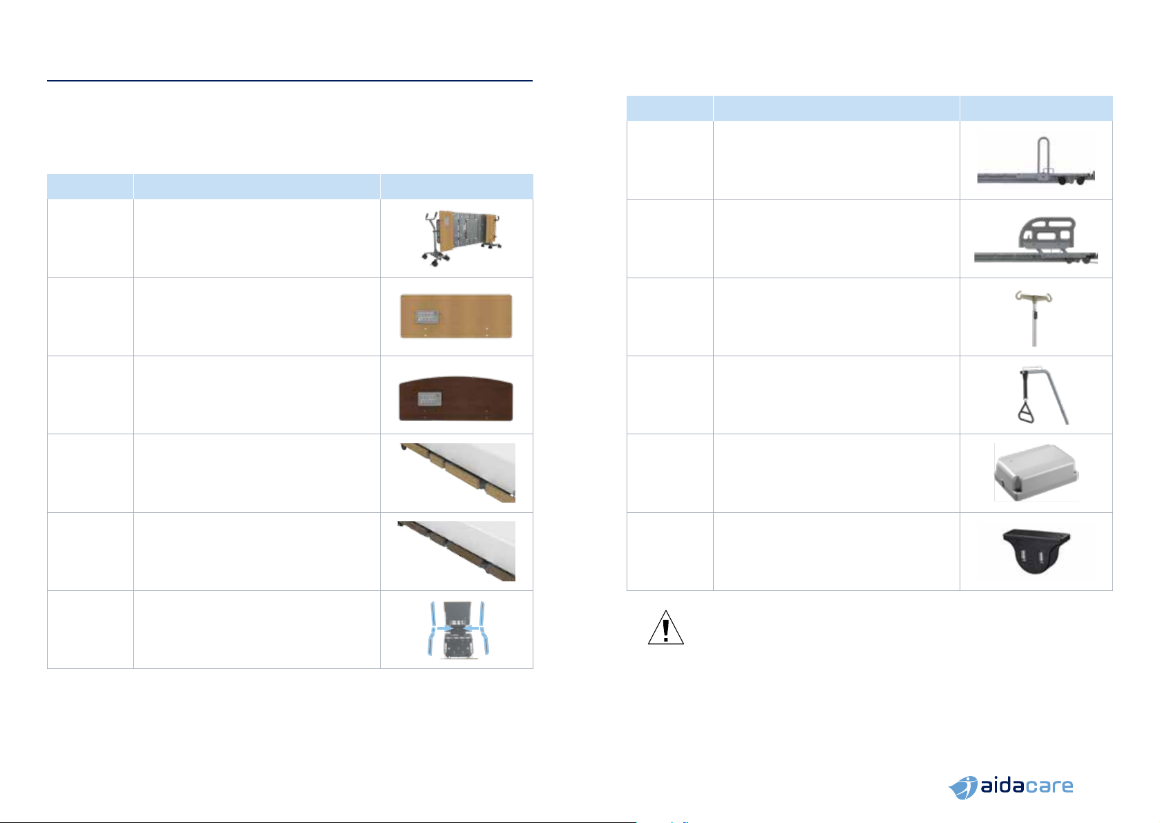
KEY FEATURES
Maximum safe working load (SWL) of the bed is 250kg
with a suggested maximum user weight of 200kg which
conservatively takes into account common accessories
used with care beds such as alternating pressure
mattresses, assist bars and foam mattresses
• ExitSafe single button
ingress / exit height
• BrakeFirst automatic safety brake
activation at lowest height
• SmartDescent automatically slows
lowering speed from 300mm
above floor level to lowest position.
Designed to improve resident
and carer safety whilst reducing
potential for damage to equipment
such as air mattress pumps
becoming trapped under the bed
• EasyMove Transport System
– transport the FL250 bed
with zero lifting for a truly safe
manual handling process
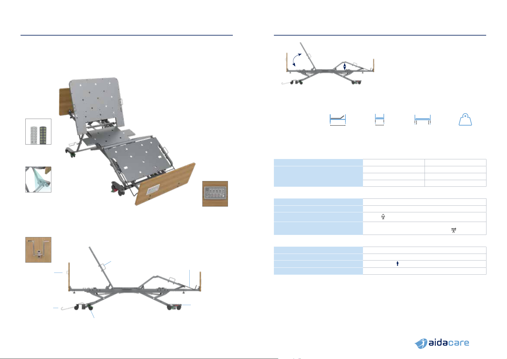
• Electrically adjusted height
range from 110mm to 740mm
• 75mm twin castors with
single activation locking
mechanism for ease of use
• Four section electrically operated
mattress platform with independent
adjustment of backrest angle
(maximum 60°) and knee
section angle (maximum 35°)
• Bi-lateral mattress retainers
with length adjustable mattress
extension retainer at foot end
• Integrated foot end
extension. Extends the bed
by 100mm or 200mm
• Large range of feature
enhancing accessories
• Removable bed ends
• Automatically adjusting
wall protection system
• Auto-regression integrated into
backrest and leg section reduces
sacral pressure, shear forces
and abdominal compression
during bed profiling
The symbols below are used throughout this owner’s manual and on the
product to identify warnings and important information. It is very important
for you to read them and understand them completely.
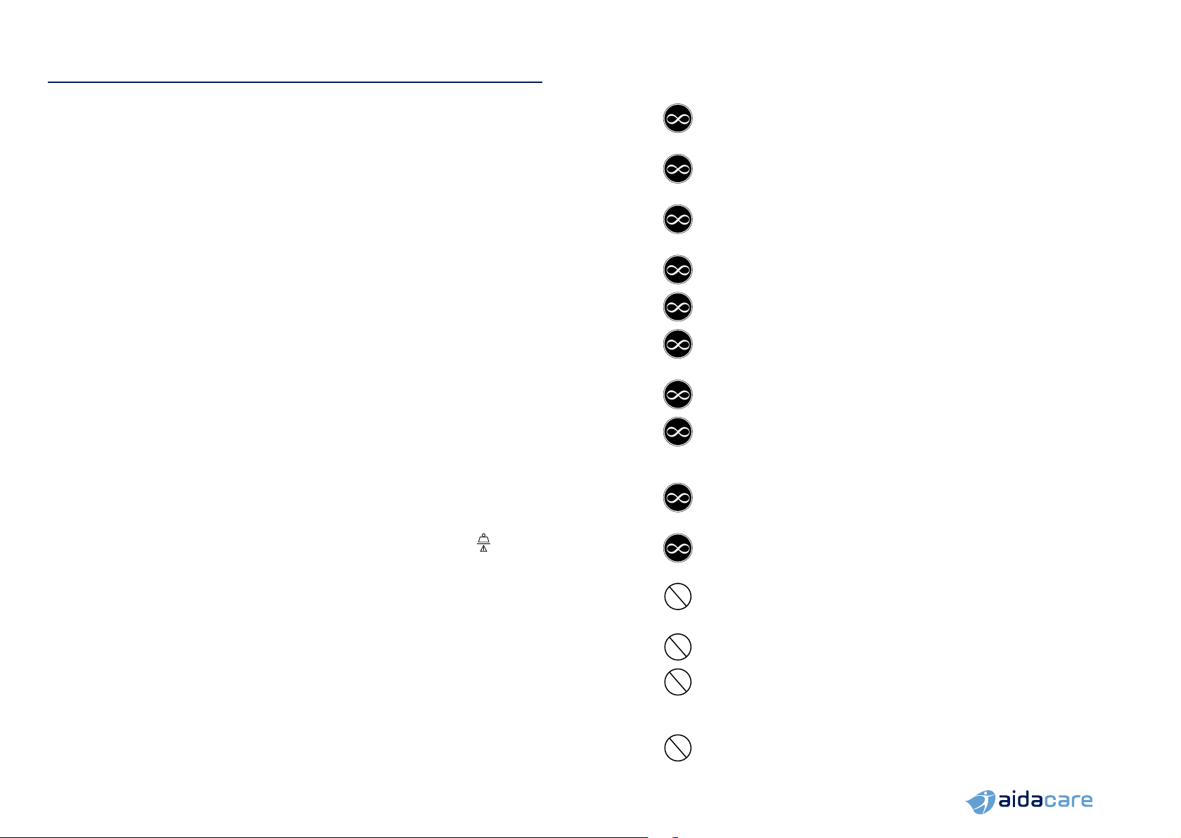
WARNING
Indicates a potentially hazardous condition/situation.
Failure to follow designated procedures can cause either
personal injury, component damage or malfunction. On
the product, this icon is represented as a black symbol on
a white triangle with a black border.
ALWAYS! These actions should be performed as specified.
Failure to perform mandatory actions can cause personal
injury and/or equipment damage.
On the product, this icon is represented as a white infinity
symbol on a black dot with a white border.
DO NOT! These actions are prohibited. These actions
should not be performed at any time or in any
circumstances. Performing a prohibited action can
cause personal injury and/or equipment damage. On the
product, this icon is represented as a white symbol with
a black circle and black slash.
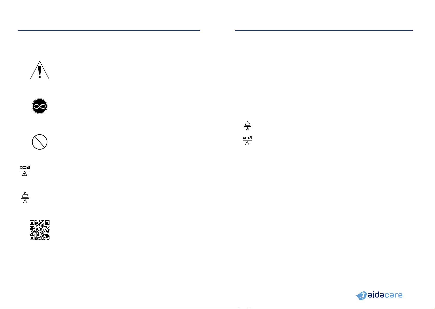
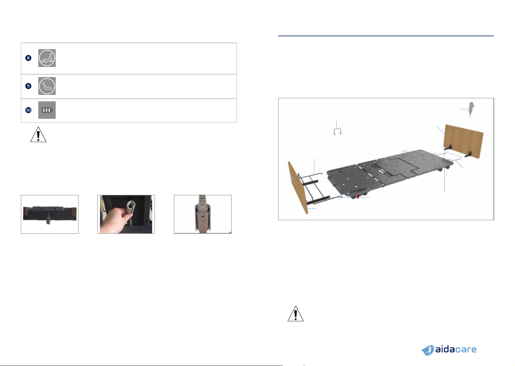
= 200kg MAXIMUM PATIENT WEIGHT. This weight represents
the total maximum weight of a patient on the bed. This
weight (200kg) should not be exceeded at any time.
= 250kg
SAFE WORKING LOAD (SWL). This weight represents
the total maximum weight that the bed can carry,
including patient, mattress, bedding, bed ends and
accessories. This weight (250kg) should not be exceeded
at any time.
Please scan the QR code or visit our website aidacare.com.au
and search ‘Aidacare FL250 (BEB046100 or BEB046150)’
to access product marketing and technical documentation.