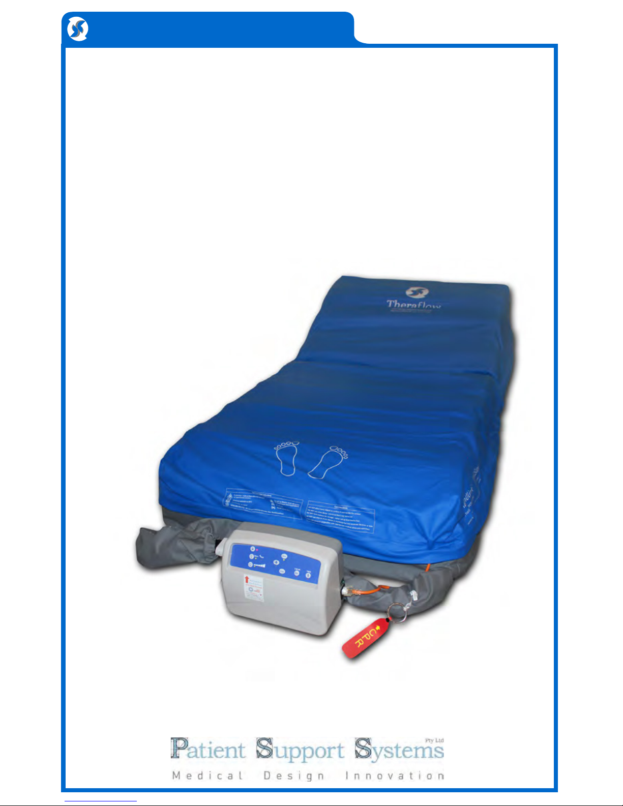
System Descripton
Congratulations on your hire or purchase of a Theraflow alternating
mattress replacement system. The Theraflow with its Dynam-U-link
cell technology and Cellstay ultra-stretch coverlet represents one of the
greatest advances in alternating support technology since its inception.
Dynam-U-link cells use elastic transfer straps so that inflating cell sets
literally pull down the deflating sets beside them. This results in faster,
more sustained pressure release.
The Cell Stay coverlet positioned between the cells and top cover comforts
and insulates the patient from the colder cells without compromising
therapy. This coverlet also guards against reperfusion injury in patients with
delicate vasculature and tissue.
Your mattress system has the following features.
Control Unit:
• Powerful yet quiet 20 LPM compressor with non-continuous operation
• Auto startup with choice of three modes - Static, Active and Care
• Choice of three comfort settings
• Incline mode for adding extra support pressure
• Simple tamper resistant control interface with audio visual diagnostics
• Easy to reach CPR side disconnection
Mattress:
• Fully welded top cover and base for complete infection control
• Removable cell section for easy separation of base for cleaning
• Four static head cells to prevent dizzyness and disorientation
• Clear PVC base bonds to any metal bed base avoiding need for straps
• Fourteen alternating Dynam-U-link cell pairs for faster, lower and
longer cell deflation
• Cell Stay insulating hi-stretch Coverlet
• Internal power cord removes chance of damage underneath the bed
System Specifications
Control Unit
Dimensions: W 25 x H 25 x D 17cm
Weight 3kg
Mode of Operation Non-Continuous
Power Rating 240V 50Hz 12VA
Transport Function Hose End Cap
Air Flow 20 Litres per Minute
Auto Startup 3
Comfort Override Control 3
Self Diagnostics 3
Audible/Visual alarm 3
Mute Function 3
Static Mode - timeout after 1 hour 3
Care Mode - timeout after 20 mins 3
Incline Mode 3
Auto Anti Tamper 3
CE Certification and C-Tick Listed
N27882
Mattress Replacement
Dimensions L 200 x W 90 x H 25cm
No. of Cells 28 (paired)
Static Head Cells (included) 4
Cell Material TPU, High Density
Top Cover Dartex/Equivalent - welded
Base Assorted PU and PVCs, welded
Cell Cycle Paired 1 in 2
Alternating Mode 14 minute cycle
Infection Control:
Welded Top Cover and Base
Internal infection control coverlet
Positioning Handles 2 aside
ARTG Certification 175810
Problem Cause Solution
Troubleshooting & FAQs
Control Unit
does not
operate or fault
light flashes &
alarm sounds
The fault light
below flashes
and alarm
sounds
Cell or Cells
rising up above
adjoining cells
There may be a
disconnection in the
power supply
There is a leak
somewhere in the
cell or air hose
connection system
A cell end press stud
has disconnected.
1. Ensure all cord connections from wall
plug, breakaway connection at head
end and pump connector are properly
seated in their sockets.
2. Check Control Unit fuse under power
socket - flick open with small flat
head screwdriver and replace fuse if
necessary.
Only use fuse type 10Amp 250Volt
1. Ensure that the CPR hose connector
is properly attached to the side of the
control unit.
2. Remove the top cover and listen for
any hiss of air from the cells. The
powerful 20 litre pump should ensure
that you can hear where there is a cell
leak. If you still cannot hear - remove
the coverlet and or run the back of
your hand along the top of the cells to
find the air leak.
Also look for any deformed cells as
these may have internal weld failures
leading to leaks of air between
separate internal chambers.
Once the faulty cell is found - remove
and replace with the same type.
3. Look for any disconnection between
hoses and their T or L connectors.
Don’t forget to also check whether the
air hoses are correctly connected to
each of the cells.
1. Open top cover and check along the
sides of the inside base section. It is
easy to see immediately if any of the
external press studs have become
disconnected.
One press stud set connects two cells
- if the studs are faulty - replace those
cells.
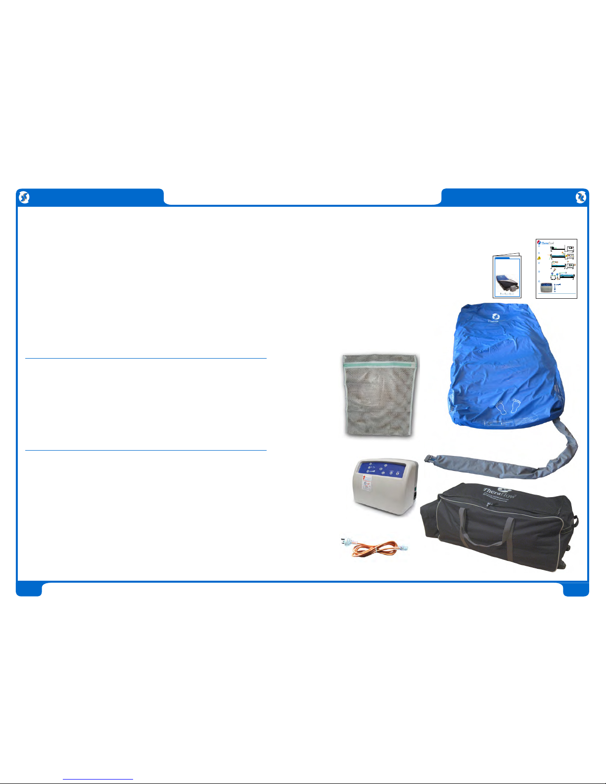
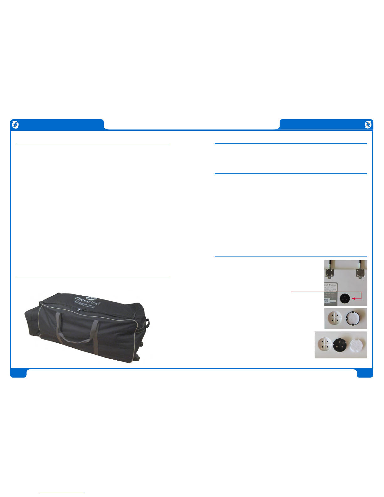
The Theraflow alternating mattress replacement system is provided with
the following standard components.
1 Alternating Mattress Replacement
with internal power cord.
2 Digital Control Unit
3 Break-Away Power Cord
4 Theraflow Operating Manual
5 Theraflow Quick Setup Guide
6 Wash Bag
7 Wheeled Carry Bag
AlternatingMattress Replacement System
Auto Quick Setup Guide
1
2
3
4
40mins
20mins
Removemattress roll
fromcarry bag and lay on
bedbase at foot end.
Tryto avoid hanging the
controlunit in an exposed
positionif a lower hang
pointis available.
Connectair hose to control
unit(Connector can attach
eitherway around)
ConnectSensor Jack to its
Portunderneath air hoses.
(ControlUnit will NOT
operatewithout sensor!)
Connectmale power cord to control unit as shown.
Connectbreakaway power
cordinto wall socket.
Turnon control unit at
switchnear power socket.
Mattresswill take up to
40minutes to inflate.
Pressand hold Unlock
buttonfor 2 seconds to
activatecontrol panel.
EngageCare Mode for
patienttransfer onto
mattress.
CareMode will auto
disengageafter 20 mins.
2secs
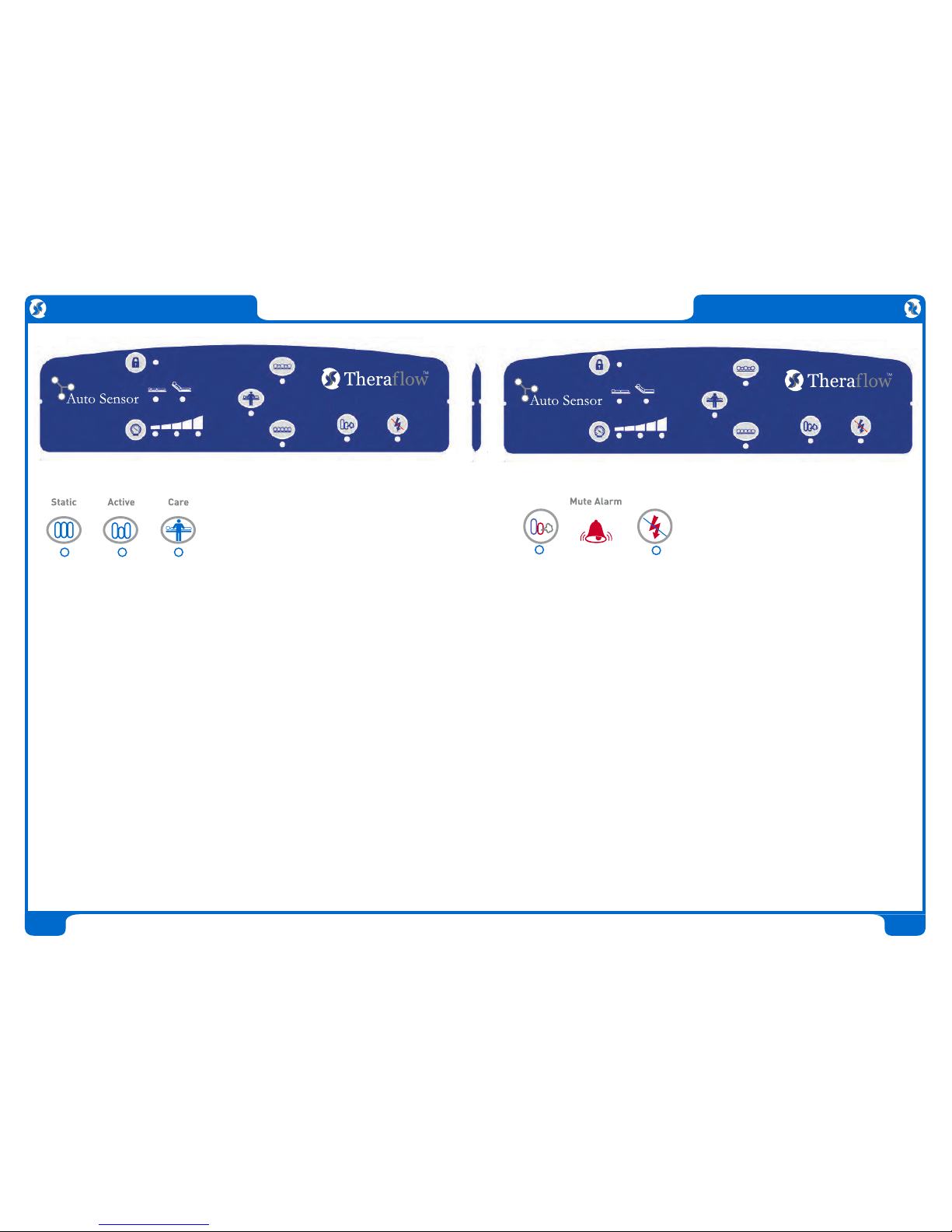
ControlUnit Operation
PatientSupport SystemsPty Ltd: Suite1A, Level 2, 802Pacific Highway,Gordon Sydney NSW Australia 2072
Tel:+61 2 9844 5456 Fax:+61 2 9844 5445 Email: info @patientsupportsystems.com
5
TheTheraflow Automatic Sensor System is designed to
automaticallyadjust to patient weight, position & profile
Pressthe pressure setting button at left
Allthree lights will flash. The system takes
8minutes to adjust to the patient’s weight
LockedMode: Press for 2 seconds to unlock all controls
ActiveMode: DefaultMode for active alternation therapy
CareMode: Maximum pressure forpatient transfers
Willdefault to Active Mode after 20 minutes
StaticMode: Engage for transport or meals for comfort
Willchange back to alternation after 1 hour
CPR
EnsureCPR tag is closed!
OperatingManual
Theraow™
AlternatingMattress Replacement Systems
ModelMRS-TFW-001 Standard
ModelMRS-TFW-001P with battery backup
ModelMRS-TFW-002P Bariatric with battery backup
7
2
4
5
3
6
1
System Components