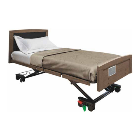
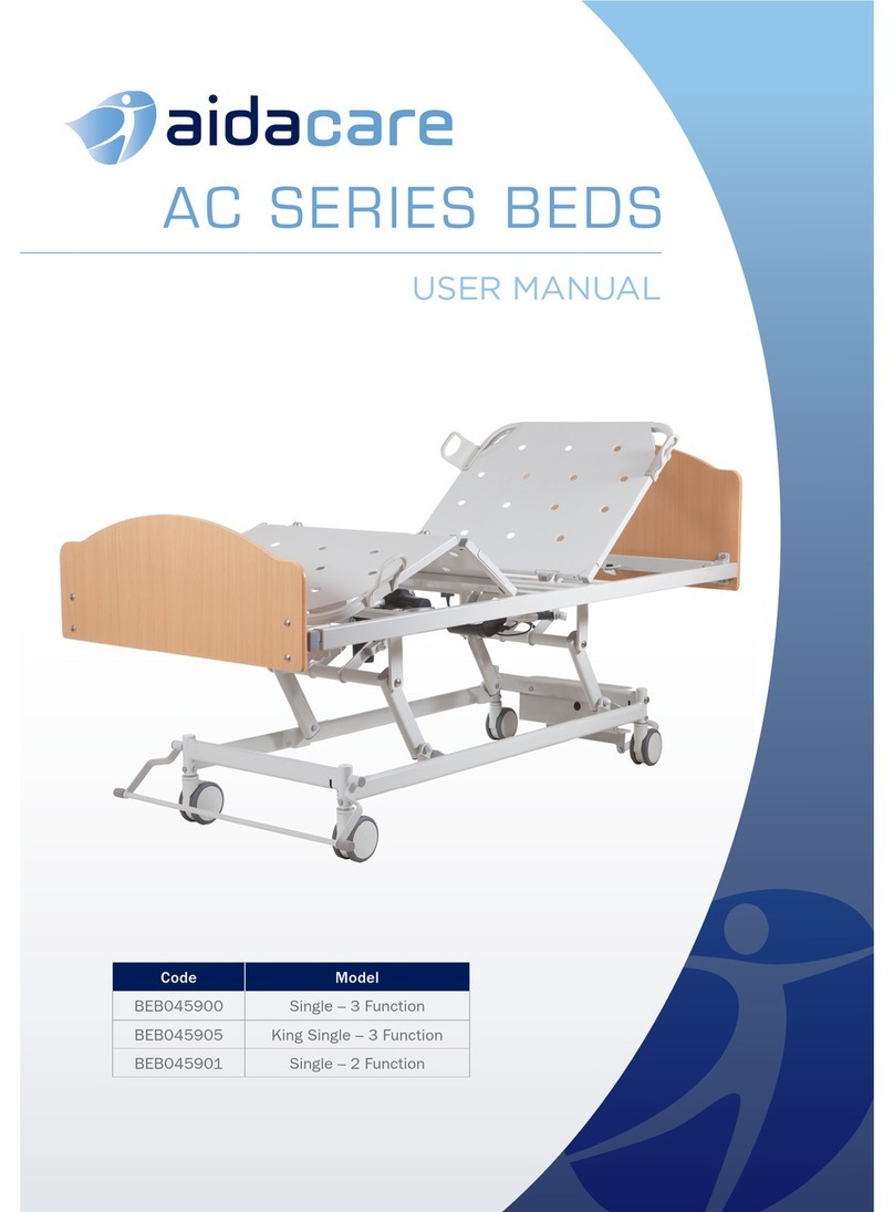
aidacare AC4 BED Single User manual

AC4 BED
Single | King Single
USER MANUAL

2 3aidacare.com.au
TABLE OF CONTENTS
1. Introduction 4
2. Safety Precautions 5
3. Electronic Functions 7
4. General Bed Operation 9
5. Specifications 14
6. Cleaning 15
7. Maintenance 15
8. Transportation and Storage 17
9. Accessories 17
10. Warranty and Service 18
Thank you for choosing this Aidacare
AC4 Bed.
This product has been specifically designed
to offer comfort, support and safety.
It is important that you read this user
manual carefully before using your
new bed.

4 5aidacare.com.au
1. INTRODUCTION
The Aidacare AC4 Bed is an electrically operated Care Bed. It has a range
of functions and positional movements that assist caregivers and provide
for patient comfort. Ease of use, functionality, serviceability and cleaning
practicality are key features of the bed. The bed has a fabricated steel
structure with a powder coated finish. The plastic components are made
from urethane, PP and POM nylon and ABS plastic.
CLINICAL APPLICATIONS AND AREA OF USE
The bed is appropriate for adult patient care under supervised
medical monitoring.
KEY FEATURES
• Maximum safe working load (SWL) of the bed is 220kg
• Electrically adjusted height range of 300mm to 750mm
• 125mm diameter twin castors with central locking brakes and steering
• Four section electrically operated mattress platform with independent
adjustment of backrest angle (maximum 70°) and knee section angle
(maximum 40°)
• Mattress retainer handles
• Integrated foot end extension. Extends the bed by 195mm
• Clamp on ¾ length folding side rails (optional accessory)
• Removable bed ends
• Wall protection system
2. SAFETY PRECAUTIONS
It is important that this User Manual is read in its entirety prior to
operating the bed. The manual is designed to ensure that users are
equipped with the information required to competently and responsibly
operate the bed and its accessories.
It is recommended that the User Manual be kept in an easily accessible
place for quick reference. If required Aidacare product specialists can
provide additional training.
All warnings and cautions within this manual should be strictly adhered
to. Failure to do so could result in harm to the patient or operator.
Warnings highlighted throughout this manual identify possible hazards
in procedures or conditions which if not followed correctly could result in
serious injury, or fatality.
Cautions highlighted throughout this manual identify possible hazards
in procedures or conditions, which if not followed correctly could result in
equipment damage, or failure.
GENERAL
• Electrical equipment can be hazardous if used incorrectly.
• Residual current devices (RCD) are not supplied with the AC4 beds.
Please consult with your Biomedical Engineer/advisor concerning
RCD requirements.
• The clinically qualified person responsible should consider the age, size
and condition of the patient before using the bed and its accessories.
• The maximum safe working load of the AC4 beds of 220kg includes the
mass of the patient, mattress and any accessories fitted to the bed.
• Maximum mattress thickness that can be used on the AC4 beds is 170mm.
• Side rails must only be used with a mattress of appropriate size, which
is approved for use with the bed.
• If a patient’s condition could lead to a possible entrapment the mattress
support platform should be left in the flat position whilst unattended.

6 7aidacare.com.au
• ALWAYS position the bed at its lowest height when unattended by
caregivers to minimise the risk of patient injury from falls when getting
in and out of the bed.
• ALWAYS use a mattress of appropriate size and type. A range of
suitable pressure reducing and pressure relieving mattresses are also
available from Aidacare.
• ALWAYS make sure that the patient is safely positioned to avoid
entrapment before operating the bed.
• ALWAYS ensure that attendant and patient limbs are free from
potential entrapment areas before operating any functions.
• ALWAYS ensure that the bed is at a suitable height to avoid stooping
or straining before transporting.
• ALWAYS apply the brakes when the bed is stationary.
• ALWAYS store the handset when not in use to avoid accidental
operation of the beds functions. The handset can be stored by hooking
it on to the side rail of the bed.
• ALWAYS ensure that all hospital lines and power cables are free from
possible entanglement with mechanical parts of the bed.
• DO NOT place the handset, or power cord across the mattress surface
of the bed when the bed is not connected to mains power. Always store
the power cord within the power cord fixtures fitted to the bed.
• DO NOT use electrically operated beds in operating theatres.
• DO NOT use electrically operated beds in the presence of flammable gases.
• DO NOT use the bed to support more than one patient. AC4 beds
are intended for single person use and may become unstable if
used incorrectly.
• DO NOT use accessories that are not designed, or approved for use
with AC4 beds.
3. ELECTRONIC FUNCTIONS
WARNING
• Ensure that the patient, caregivers and or other equipment
is not positioned to become either trapped or crushed during
bed adjustment.
• Ensure that the coiled power lead is not stretched excessively.
• Ensure that the handset and electrical supply cables cannot become
entangled with moving parts of the bed.
• DISCONNECT the electrical power cable from the mains and store
before transporting the bed.
• If the power cable shows any sign of damage, replace immediately.
CAUTION
• Do not operate the bed controls for more than the prescribed duty
cycle of the control system. (See rate load page 11)

8 9aidacare.com.au
4. GENERAL BED OPERATION
4.1 CASTOR SYSTEM – BRAKES & STEERING
4.1.1 CENTRAL LOCKING CASTORS
AC4 Series beds have a central locking castor system that is operated with
a full width foot pedal.
• With the pedal in the down Brake position, the brakes are applied to
three castors of the bed simultaneously and the bed is immobilised.
• With the pedals in the horizontal Free position, the brakes are released
and the bed can be moved in any direction.
• With the pedals in the raised Steer/Track position, one steering castor
at the head end of the bed is engaged to provide better control when
pushing the bed in a straight line.
CENTRAL LOCK PEDAL POSITIONS
Brake Free Steer/Track
CAUTION:
• Disconnect the bed power cord before moving the bed.
• Do not remove the power cord from the source by pulling on the cord.
• Do not use the beds side rails to manoeuvre the bed.
• Do not pull on the power cord, or handset cord to manoeuvre the bed.
• Always apply the brakes when the bed is in a stationary position.
3.1 HANDSET BUTTON OPERATION
AC4 beds are powered by three electric actuators, which are controlled
by the buttons on the handset. Adjustment occurs only while a button
is pressed. Adjustment will stop when the button is released, or the
movement selection reaches the end of its range of adjustment.
1
Backrest Adjustment
To move the backrest up or down, press and hold the appropriate
button on the handset. The backrest can be adjusted through a
range of between 0° and 70°.
WARNING: Care should be taken whilst operating the backrest
function to ensure hands and fingers are free from potential
squeeze hazards.
2
Mattress Platform Height Adjustment
To move the mattress platform up or down, press and hold the
appropriate button on the handset. The platform height can be
adjusted from a low of 300mm to a high of 750mm.
3
Knee Positioning Adjustment
To move the knee positioning section up and down, press and
hold the appropriate button on the handset. The knee section is
adjustable through a range of 0° to 40°.
1
2
3

10 11aidacare.com.au
4.2 BED EXTENSION
The integrated bed extension can add an extra 200mm of length
to the mattress platform.
MOVING BED EXTENSION FROM CLOSEDSTANDARD
BED POSITION
1. The bed extension is held in position by two threaded hand wheels
on either side of the bed. Unscrew (anti clockwise) the hand wheels on
both sides. It is not necessary to remove the hand wheels completely,
unscrewing them by approximately 10mm of thread length will allow for
the internal lock nut to travel freely past the thread of the hand wheel.
2. With both hand wheels now unscrewed, gently pull with an even
force on both sides of the bed end. (2) Indicates the best position for
easier extension if used on both sides of the panel at the same time.
3. Lock hand wheels in place on either side to lock bed end in.
4. Return the hand wheels back to their locked position (1)
To reposition the bed end back to the closed/standard bed position
use the same technique as above.
1
2
WARNING: The bed extension is designed for use as a bed extension
only and is not meant to support the body weight of a person sitting.
The extra length of the bed with extra load can also make the bed
unstable potentially resulting in injury to the user and patient.
4.3 FOLD DOWN SIDE RAILS (OPTIONAL)
Bed rails (optional) are easily fitted by clamping to the bed frame.
When fitted correctly, AC4 bed rails meet the requirements of Medical
equipment international standard IEC 60601-2-52, which includes specific
rail requirements.
4.3.1 FITTING THE SIDE RAILS
NOTE: The rails are a left and right hand set and when fitted correctly fold
down towards the foot end of the bed.
1. Before fitting the rails unscrew the hand wheel to bring the locking
clamp into an open neutral position which will allow the rail to fit over
the side rail of the bed.
Closed Position Open Position
2. With both hand wheels now unscrewed, lift the rail into position. It
is important that the rails are fitted to a specific position on the bed,
which is indicated by the bolt on top of the bed frame. Position the
rail over the bolt and tighten the hand wheel to the closed position.

12 13aidacare.com.au
4.3.2 SIDE RAIL OPERATION
The rails are either fully raised, or folded down closed. When the side rail is
raised to its full height position it will automatically lock in the positioning
hole on the rail clamp plate. The release/lock knob feature can be both
visually and audibly confirmed.
WARNING: Do not operate side rails when there is potential of entrapment
or crushing to the patient, caregivers, visitors and/or other equipment.
Side Rail Operation
To raise the side: Lift the top rail until the locating
pin/knob automatically clicks into its locked
position at maximum height.
To lower the side: Hold the top rail near the foot
end of the bed (1) and gently pull out the red
operating knob (2) lowering the side towards
the foot of the bed whilst controlling the descent
speed. As the side begins to be lowered the
operating knob can be released.
WARNING: Care should be taken whilst operating
the side rails to ensure hands and fingers are kept
away from potential squeeze hazards. Side rails
should only be used after clinical assessment and
within organisational policy and guidelines.
4.3.3 SIDE RAIL SAFETY LOCK INDICATOR
The side rail locating pin has a yellow coating
that allows for visual inspection of the locking
device. When the side rail is in the raised position,
viewing the release knob from the side there
should be no yellow shaft visible. If there is yellow
shaft visible the safety side is NOT securely locked
in the upright position and needs to be adjusted.
The yellow coating should NOT be visible from
above when the safety side is correctly locked
in position.
Side rail release and lock knob shown
in unlocked and locked positions
Unlocked
Locked
WARNING: After adjustment of the side rail visually check the locking
pin location. There should be no yellow shaft on the locking pin visible if
locked correctly. DO NOT use other manufacturer’s side rails on AC4 beds.
4.4 KING SINGLE EXTENDABLE FOOT END MATTRESS RETAINER
AC4 beds come standard with an extendable foot-end mattress-retainer
that is used in conjunction with the bed extension.
To extend the mattress retainer hold vertically and insert ends into 1 of
the 3 receiving keyhole mounts which are 100mm spaced at the foot end
of the mattress platform to match the desired bed extension (nil, 100mm,
200mm). Lower the retainer to the mattress platform. It will now be locked
in place at the mount keyholes.
Retaining Pin
1
2

14 15aidacare.com.au
5. SPECIFICATIONS
SIZE SINGLE KING SINGLE
BASIC DIMENSIONS
Overall Length 2100–2300 mm
Overall Width 920 mm 1070 mm
Overall Width (rails fitted) 1030 mm 1200 mm
Mattress Surface Length
(between panels) 2000–2200 mm
Bed Platform Height
Range 300–750 mm
Back Rest Angle
Adjustment 0° to 70°
Knee Bend Angle
Adjustment 0° to 40°
MATTRESS SIZE
Recommended
Mattress Size
Maximum Mattress Depth
Width = 900 mm Width = 1050 mm
Length = 2000 mm
Depth = 150 mm
BED WEIGHT & SAFE WORKING LOAD
Without Side Rails 112 kg 116 kg
SWL 220 kg
ELECTRIC PARAMETER
Power Input 100–240V AC 50Hz, Max current 1A
Rate Load Interruption 10%, Max 2 minutes / 18 minutes
Leakage Protection Class 1 Type B
Waterproof Grade IP54
STANDARD
Aidacare AC4 beds are designed and manufactured in compliance
with International Standard IEC 60601-2-52.
WARNING
Before cleaning always disconnect the bed from the mains power source.
Note: It is strongly recommended that protective clothing be used
when cleaning.
Note: The following procedure also applies to the beds accessories,
but does not include mattresses.
• Wipe the beds surfaces with a soft cloth moistened with hot water
and mild detergent (or the facilities recommended cleaning solution).
It is recommended that the cloth be a white material to prevent
bleeding of die colours to the bed. Take extra care in areas that can
harbour dirt or dust.
• Rinse with clean water and a dry clean cloth.
• To remove potentially infectious materials such as body fluids, or when
the bed has been used by someone with a known infection. Clean with
NaDCC (e.g. Presept, Actichlor) at 10,000 ppm of available chlorine.
Rinse and dry.
• Allow the cleaned parts to dry before replacing the mattress.
CAUTION
Do not use abrasive Hypocarbonate or Phenolic compounds or pads.
7. MAINTENANCE
To prolong the working life of the bed and for trouble free operation it is
recommended that routine inspections should be performed by a person
who is suitably qualified and well acquainted with the design, use and care
of AC4 beds.
If inspection reveals that the safety of the bed is jeopardised in any way,
it should be IMMEDIATELY WITHDRAWN FROM SERVICE, tagged as such
and the owner notified.
6. CLEANING

16 17aidacare.com.au
The following preventative maintenance procedures should be carried out
every 12 months.
Electrical test & tag – where lifters are in use in a commercial environment
then the testing regime applied should align with the risk assessment
made by the owner for safety and other compliance requirements.
NOTE: Other than general maintenance activities all other service or
repair work must be performed by qualified and trained persons who
are approved by Aidacare.
WARNING: The bed must be disconnected from the mains power supply
before starting any maintenance activity.
General
1
Examine all the warning signs on the bed, examine the bed for
obvious signs of damage. All aspects of the equipment should
operate as intended. Check that all nuts, bolts and other fasteners
are tight and are not missing.
2Examine flexible cables and conduits for cuts, cracks, abrasions
or other deterioration.
3
Check that the power supply plug is not damaged. If either the
power cable or plug is damaged then both the cable and plug
must be replaced as a complete assembly by an approved service
agent.
Central Locking System
1Apply the brakes and push the bed forwards. If any of the four
braking castors rotate the brake is not fully effective.
2Check the two steering lock castors for correct operation.
3If either the brakes or the steering locks are not working
correctly contact an approved service agent.
Side Rails (if fitted)
1
The locking pin mechanism and striker plate arrangement should
be checked every three months.
Inspect the side rails for general wear and tear on fittings and
pivot joints every six months.
Check for rust, structural integrity of welds and paint finish every
twelve months.
2
Raise the side rail to the upright position until the locking
mechanism clicks into place. Refer to the operating procedures
starting on page 10 of this manual for further instruction.
3
Check that the there is no yellow shaft visible. In the locked
position the red on the locking pin shaft should not be visible
from above
4If the red shaft is visible when the side rail is in the raised and
locked position, contact Aidacare for service advice.
5
Check that the rails pivot axles are securely fitted to the bed. The
pivot axles are locked into place by the manufacturer by a 10mm
lock nut.
8. TRANSPORT & STORAGE
Handle With Care.
AC4 beds should be stored in a clean, dry, well ventilated area.
Do not drop and avoid shock or violent impact when transporting.
The following limits apply during transport and or a storage period
of up to 15 weeks duration:
Ambient temperature -25°C – 70°C
Relative humidity 10% – 75%
Air pressure 50 kPa – 106 kPa

18 19aidacare.com.au
The following limits apply to normal operating conditions and or
periods of storage longer than 15 weeks:
Ambient temperature 10°C – 40°C
Relative humidity 30% – 75%
Air pressure 70 kPa – 106 kPa
9. ACCESSORIES
A range of AC4 accessories are available. In addition to the below listed
accessories, Aidacare specializes in other complimentary products such as
foam mattresses, pressure care surfaces, over bed tables, side lockers and
adjustable day chairs. Please contact Customer Service on 1300 133 120 for
further information.
Product code Description
BEA829100 3/4 Folding Side Rails
BEA829140 Self Help Pole
BEA029710 IV Pole
BEA829150 Padded Surround (Single)
BEA829160 Padded Surround (King Single)
WARNING: Do not use accessories that have not been designed for use
with the AC4 beds.
7. WARRANTY & SERVICE
Aidacare AC4 beds carry a comprehensive warranty as detailed below.
Please keep proof of purchase for proof of warranty commencement.
YEARS WARRANTY
FRAME
10
YEARS WARRANTY
ELECTRONICS
3
YEAR WARRANTY
HANDSETS & CABLE
1
Consumer Warranty Against Defects:
Aidacare is bound by Australian Consumer Law in respect to Warranty
Against Defects. A copy of the Aidacare Warranty Against Defects
statement is available on the Aidacare homepage at aidacare.com.au. All
warranty matters should be directed to Aidacare Customer Service on
1300 133 120.
Aidacare does not warrant against excessive or incorrect use, modification
or any situation that could not be deemed as fair wear and tear. This is a
back to base warranty and does not cover freight costs pertaining to the
return of any items under warranty. Aidacare acknowledges and conforms
to all ACCC guidelines around consumer rights. For further information
Aidacare will not warrant the safety and or correct functioning of products
where any original components have been changed or modified by
non-Aidacare approved and trained service & maintenance staff or external
providers. Furthermore, safety is not guaranteed where components have
been replaced with non-original Aidacare approved parts. If any faults
are detected upon receipt of this product please phone Aidacare. Any
faults that are detected during normal use should be reported to Aidacare
immediately to determine if warranty conditions apply and if so, the
necessary repair or replacement work to be completed.
Spare parts list is available upon request.
For servicing, preventative maintenance and any other questions
regarding this or any other Aidacare product please contact:
Aidacare Pty Ltd
Building 3A, 1 Moorebank Avenue, Moorebank NSW 2170
T: 1300 133 120
W: aidacare.com.au
E: produc[email protected]

ABUM18.10 050822
AIDACARE PTY LTD
Building 3A, 1 Moorebank Avenue,
Moorebank NSW Australia 2170
1300 133 120 | aspirecare.com.au
MADE IN PRC
This manual suits for next models
1
Table of contents
Other aidacare Medical Equipment manuals
Popular Medical Equipment manuals by other brands

Zimmer
Zimmer enPulsPro Instructions for use

Kodak
Kodak HEALTH SCIENCES MINILOADER 2 Plus Low Voltage... installation instructions

THERMODx
THERMODx Warm Blocks 360 user manual

Schick Dental
Schick Dental G1 Concept operating instructions

Danmeter
Danmeter elpha ii 1000 Practical guide

Otto Bock
Otto Bock Genium Protector 4X880 Series Instructions for use

Thought Technology
Thought Technology eVu TPS user guide

ALSA
ALSA EXCELL MCDSe Series Service manual

Bodypoint
Bodypoint Ankle Huggers FT210 Installation and user instructions

Teesa
Teesa PX50 owner's manual

Ametek
Ametek Reichert ClearChart2 user guide

Terragene
Terragene BIONOVA IC10FRLCD Instructions for use