Aim MXL Pista User manual

MXL
USER MANUAL

MXL
User manual
Release 1.13
MXL, with all its versions (Strada, Pista, Pro, Pro05) belongs to the new generation
of AIM data acquisition systems for car/bike races.
Equipped with a beautiful and wide display, easy to use, multi-functional and fully
configurable, it fits any need and can record in detail driver’s and vehicle
performances.
MXL is part of AIM Total Racing Solution, that includes also Race Studio 2 software
to configure the logger and download its data.
MXL allows to monitor and show RPM, speed, engaged gear, lap/split times and data
sampled by other custom sensors.
MXL has also a backlight, very useful during night races or in low light conditions.
Moreover, thanks to the lateral g-sensor or to the external gyroscope it is possible to
create the track map to relate sampled data to the position on the track.
Always versatile, MXL is available with different non volatile internal RAM memory
dimensions: 128kb (Strada), 8Mb (Pista/PRO) or 16Mb (PRO 05). The memory is
saved also when the logger is switched off.
The logger has a lateral USB port used to connect it to a PC. Thanks to MemoryKey,
moreover, it is possible to download data with no need of a PC on the track.
MXL is a modular system that, using the CAN bus, can increase every day its
potentialities. It is possible to connect it not only to a series of channels multipliers
(Data Hub, TC Hub, etc), but also to a Lambda Controller, to the GPS Module with
lap timer function as well as to a Video system (DaVid).
Warning: any documentation mentioned in this user manual can be freely
downloaded from AIM corporate website at www.aim-sportline.com.
Thanks for choosing an AIM product!
www.aim-sportline.com 1

MXL
User manual
Release 1.13
INDEX
1 – MXL kits, optional and part numbers................................................................ 3
1.1 – MXL Strada kit, optional and part numbers ........................................................................ 3
1.2 – MXL Pista kit, optional and part numbers........................................................................... 3
1.3 – MXL Pro05 kit, optional and part numbers.......................................................................... 4
1.4 – MXL Expansions .................................................................................................................... 4
2 – MXL installation and power ............................................................................... 5
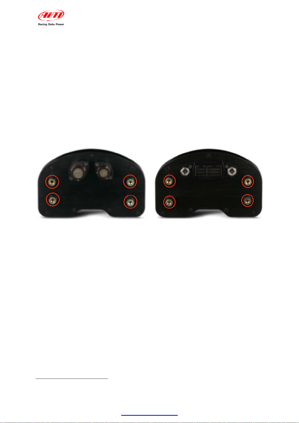
2.1 – How to install MXL................................................................................................................. 5
2.2 – How to power MXL................................................................................................................. 5
2.2.1 – the GND.......................................................................................................................... 6
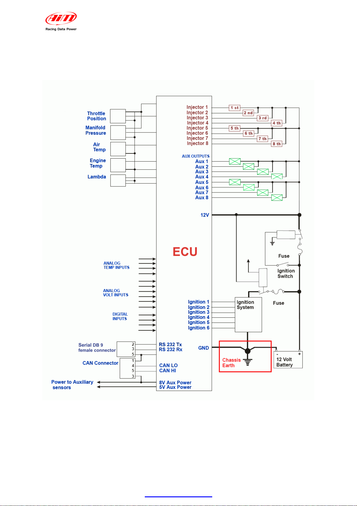
2.3 – How to connect MXL to the ECU.......................................................................................... 7
2.4 – How to sample the RPM signal............................................................................................. 8
2.4.1 – Sampling the RPM via CAN bus/RS232 ........................................................................ 8
2.4.2 – Pre-condition to sample the RPM in another way.......................................................... 8
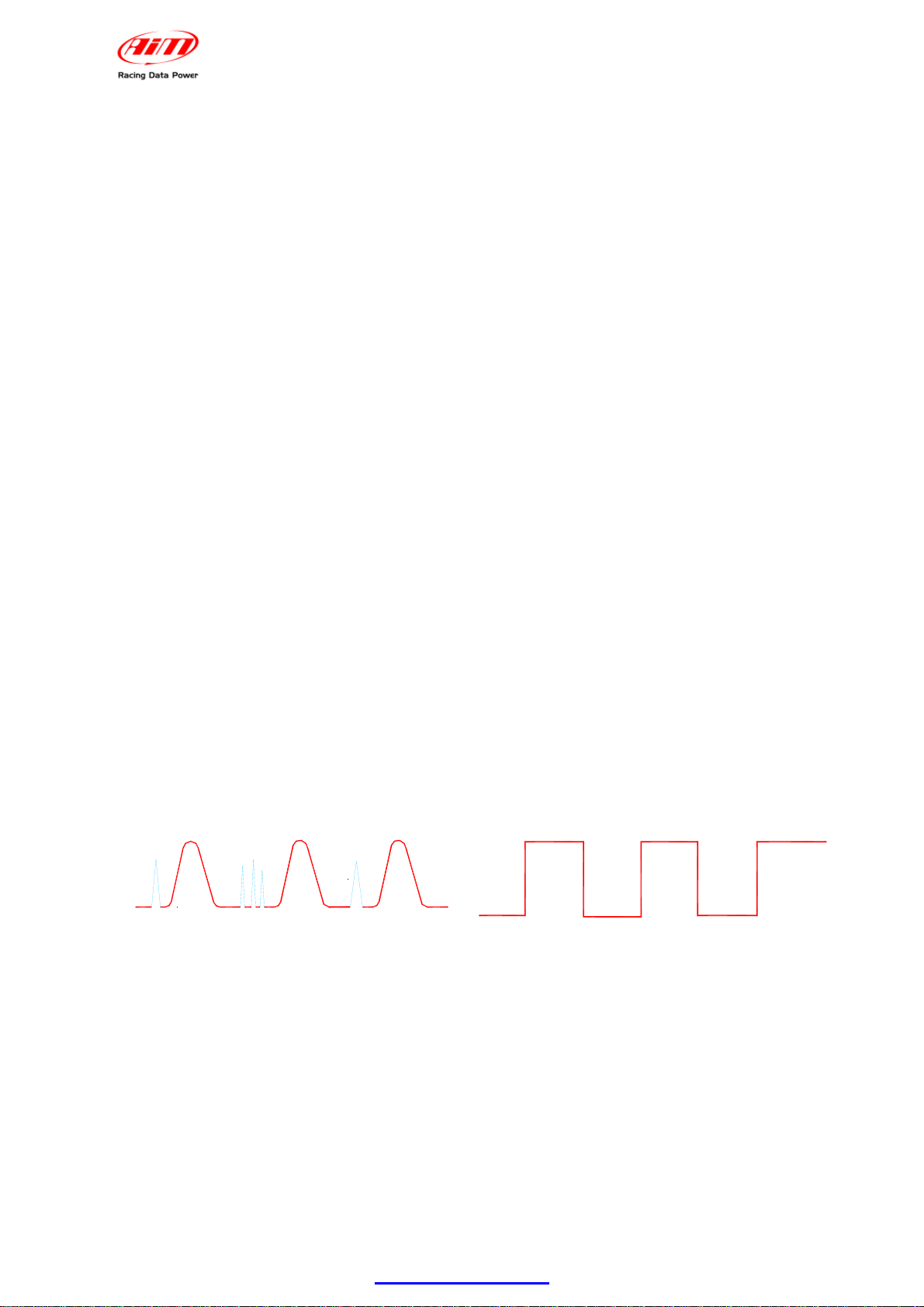
2.4.3 – Sampling the RPM from the ECU through a square wave signal .................................. 8
2.4.4 – Sampling the RPM from the coil: low voltage RPM input............................................. 10
2.5 – How to connect MXL analog channels.............................................................................. 11
2.6 – How to install and power transmitter and receiver .......................................................... 12
2.6.1 – Infrared transmitters ..................................................................................................... 12
2.6.2 – The infrared transmitter................................................................................................ 14
2.7 – How to connect MXL to the GPS Module .......................................................................... 15
2.7.1 – GPS Module and the Lap timer function...................................................................... 16
2.7.2 – GPS Manager Software................................................................................................ 16
2.8 – How to connect MXL to the MemoryKey ........................................................................... 17
3 – MXL display....................................................................................................... 18
3.1 – Forecast Lap time................................................................................................................ 19
3.2 – Alarm led and shift light...................................................................................................... 20
3.3 – Other useful information..................................................................................................... 20
4 – MXL: software, driver, configuration, transmission, download, online....... 21
5 – MXL keyboard function.................................................................................... 22
5.1 – Data recall............................................................................................................................. 22
5.2 – Other keyboard functions................................................................................................... 24
5.2.1 – Backlight....................................................................................................................... 24
5.2.2 – Setting GPS lap timer laps and splits........................................................................... 24
5.2.3 – Total running................................................................................................................. 24
5.2.3 – Odometer (not resettable) ............................................................................................ 24
5.2.4 – Date and time............................................................................................................... 25
5.2.5 – Shift lights..................................................................................................................... 25
5.2.6 – System Information....................................................................................................... 26
5.2.7 – Demo mode.................................................................................................................. 26
6 – MXL memory..................................................................................................... 27
6.1 – Memory architecture: .......................................................................................................... 27
6.2 – Memory working way........................................................................................................... 27
7 – MXL maintenance............................................................................................. 28
Appendix “A” – Technical drawings..................................................................... 29
A.1 – Loggers pinout .................................................................................................................... 29
A.2 – MXL Strada/Pista wirings ................................................................................................... 33
A.3 – MXL Pro05 wirings.............................................................................................................. 37
A.4 – USB Cable............................................................................................................................ 42
www.aim-sportline.com 2

MXL
User manual
Release 1.13
01 – MXL kits, optional and part numbers
AIM developed different MXL kits to fit any situation. Here below a description of
each standard kit with the related optionals.
Warning: MXL Pro is out of production, replaced by MXL Pro05.
81.1 – MXL Strada kit, optional and part numbers
MXL Strada standard kit: X10MXLS000000
•MXL Strada
•Power wiring
•ECU CAN/RS232 interface cable
•USB cable for PC interface
•Race Studio 2 software CD
MXL Strada Optional:
•Kit basic sensors (RPM, speed, water temperature) + wiring: X10MXLKS00000
•Infrared receiver with 90 cable: X41RX12090
•Infrared lap transmitter: X02TXKMA01
•Infrared split transmitter: X02TXSPLIT0
•Expansions (see related paragraph)
91.2 – MXL Pista kit, optional and part numbers
MXL Pista standard kit: X10MXLC000000
•MXL Pista
•Complete wiring including power and ECU CAN/RS232 interface
•USB cable for PC interface and data download
•1 speed sensor + cable
•2 temperature sensors + cable
•1 RPM sensor + cable
•Infrared lap transmitter
•Infrared receiver with 90 cm cable
•Race Studio 2 Software CD
MXL Pista optionals:
•Infrared split transmitter: X02TXSPLIT0
•Expansions (see related paragraph)
www.aim-sportline.com 3

MXL
User manual
Release 1.13
181.3 – MXL Pro05 kit, optional and part numbers
MXL Pro05 standard kit: X15MXLP000000
•MXL Pro05
•one 22 pins not cabled Deutsch type connector
•one 37 pins not cabled Deutsch type connector
•USB cable for PC interface and data download
•1 speed sensor + cable
•2 temperature sensors + cable
•1 RPM sensor + cable
•Infrared lap transmitter
•1 infrared lap transmitter with 90 cm cable
•Race Studio 2 software CD
MXL Pro05 Optional:
•Wiring for 22 pins Deutsch type connector: V02554200
•Wiring for 37 pins Deutsch type connector: V02554240
•Infrared split transmitter: X02TXSPLIT0
•Expansions (see related paragraph)
101.4 – MXL Expansions
•CAN Extension: X08EXCAN00
•Channel expansion X08CHEXUC
•Data Hub with 40 cm cable: X08HUB010
•Data Hub with150 cm cable: X08HUB150
•DaVid Slave Expansion: X01DVMKSE000
•DaVid Slave Expansion cameras PAL protocol: X01CAMPAL
•LCU-ONE CAN: X08LCU03K0
•LCU-ONE CAN+Analog X08LCUKAOCRS
•MemoryKey (except for MXL Strada): X50MEPC00
•GPS Module with 125 cm cable: X40GPS3BM125
•GPS Module with 400 cm cable: X40GPS3BM400
•TC Hub (CAN): X08UTCCTC
WARNING: visit www.aim-sportline.com for further information concerning
expansions and/or to download the documentation.
www.aim-sportline.com 4

MXL
User manual
Release 1.13
www.aim-sportline.com 5
12 – MXL installation and power
112.1 – How to install MXL
To install MXL follow these instructions:
•choose a place where the display is not in contact with oil or fuel.
•be sure that the logger is not installed close to heat sources.
•to correctly measure lateral acceleration through the internal lateral
accelerometer1install MXL vertically and with the display perpendicular to the
vehicle speed;
•avoid rigid connections between the logger display and the vehicle chassis and
protect the logger from vibrations using the stock anti-vibration mountings
highlighted in the images below.
122.2 – How to power MXL
To power MXL:
•connect the logger to an external 9-15 VDC power source (the vehicle battery
for example). Warning: do not exceed these limits.
•connect the red cable to the battery positive pole (+) and the black cable to the
battery negative pole (-).
To save the battery charge it is suggested to power MXL through the vehicle master
switch.
1Included in the standard kit except for MXL Strada that does not support it.

MXL
User manual
Release 1.13
432.2.1 – the GND
For a correct powering and signal stability it is suggested to connect the cable
labelled GND out coming from MXL power wiring to the vehicle chassis earth.
www.aim-sportline.com 6

MXL
User manual
Release 1.13
192.3 – How to connect MXL to the ECU
MXL can sample data out coming from the ECU using the proper CAN/RS232
interface cable.
To know if the vehicle ECU is supported by MXL - and for further information
concerning ECU and AIM loggers connection - refer to the related documentation
freely downloadable from AIM corporate website at:
http://www.aim-sportline.com/pages/download/section_documentation_ecus.htm
In case the conversion of non-standard CAN or RS232 lines is needed, contact our
technical support.
It is suggested to always refer to the ECU user manual for any further information
concerning pins and cables connection. Moreover - considering that ECU
manufacturers constantly improve their products - refer to their websites for more
updated information.
To connect MXL to the ECU use a serial RS232 or a CAN cable and connect it to the
corresponding non cabled wirings of the logger wiring.
In case an AIM wiring is used all cable are labelled, otherwise it is necessary to
identify the cables.
www.aim-sportline.com 7

MXL
User manual
Release 1.13
www.aim-sportline.com 8
202.4 – How to sample the RPM signal
MXL can sample the RPM signal in different ways:
•from the ECU via CAN bus or RS232;
•from the ECU through a square wave signal (from 8 to 50 V);
•from the coil: low voltage input (from 150 o 450 V).
312.4.1 – Sampling the RPM via CAN bus/RS232
To sample RPM via CAN bus/RS232 refer to the chapter concerning the ECU
connection.
322.4.2 – Pre-condition to sample the RPM in another way
To sample RPM signal from the ECU through a square wave signal or through the
coil it is necessary:
•MXL Strada + kit basic sensors (optional – part number X10MXLKS00000;
draw code 04.554.02);
•MXL Pista standard kit;
•MXL Pro05 + 22 pins Deutsch type connector wiring (optional – part number
V02554540; draw code 04.554.24) + 37 pins Deutsch type connector wiring
(optional – part number V02554240; draw code 04.554.20).
332.4.3 – Sampling the RPM from the ECU through a square wave signal
To sample the RPM from the ECU using a square wave, connect:
•the white cable labelled “RPM” (MXL Strada/Pista) of the logger wiring to the
ECU RPM signal;
•the blue cable labelled “RPM 8-50 V” of the 37 pins Deutsch type connector
wiring (MXL Pro05) to the ECU RPM signal.
Always refer to the ECU user manual for further information.
In case ECU output signal is not a steady square wave, an RPM adaptor (optional) is
needed. The images here below show a not square RPM signal on the left and a
filtered one on the right.
ECU
0 V
12 V

MXL
User manual
Release 1.13
To connect the filter, follow this procedure.
•Connect the blue cable labelled “RPM form” to the cable labelled “RPM” of MXL
Strada/Pista wiring.
•Connect the blue adapter cable, labelled “RPM form” to the blue cable labelled
“RPM 8-50V” of MXL Pro05 wiring – pin 12 of 37 pins Deutsch type connector.
•Connect the red interface cable labelled “V battery” to positive pole of the
vehicle battery. It is suggested to connect the red cable downstream the vehicle
master switch.
•Connect the interface black cable - labelled GND - to the vehicle chassis earth
(refer to GND paragraph of this user manual for further information).
•Connect the adapter cable labelled “RPM-ECU 4-50 V” to the RPM signal out
coming from the ECU.
www.aim-sportline.com 9

MXL
User manual
Release 1.13
www.aim-sportline.com 10
442.4.4 – Sampling the RPM from the coil: low voltage RPM input
To sample the RPM signal from the coil on a low voltage input (from 150 to 400 V),
connect:
•cable labelled “RPM” (MXL Strada/Pista) to the ECU RPM output that
manages the coil;
•cable labelled “RPM 150-450V” (MXL Pro05) to the ECU RPM output that
manages the coil.
In case the vehicle is not equipped with an ECU take the signal directly from
the low tension coil control of the coil.
MXL may not sample correctly the coil signal because this looks unstable. The
images below show on the left a non filtered unstable coil signal and on the right a
filtered one.
Bobina
12 V
250 - 400 V
0 V
0 V
V12
To filter the signal use an “RPM coil-ECU” adaptor (optional shown here below). It is
a double purpose filter that allows to sample the RPM from the coil and squares the
signal wave form.
•connect the blue adaptor cable labelled “RPM form” to the cable labelled “RPM”
of MXL Strada/Pista wiring.
•connect the blue adapter cable, labelled “RPM form” to the blue cable labelled
“RPM 8-50V” of MXL Pro05 wiring – pin 12 of 37 pins Deutsch type connector.
•connect the red interface cable labelled “V battery” to the positive pole of the
vehicle battery. It is suggested to connect the red cable downstream the vehicle
master switch.
•connect the black interface cable - labelled GND - to the chassis earth of the
vehicle wiring (refer to GND paragraph of this user manual for further
information).
•connect the adapter cable labelled “RPM-Coil 150-400 V” to the coil control.

MXL
User manual
Release 1.13
212.5 – How to connect MXL analog channels
MXL is equipped with numerous analog and digital channels and their number
changes depending on the model.
MXL Strada/Pista models have 8 analog channels and 3 digital channels:
•RPM
•1 speed channel
•Lap Time.
MXL Pro model has 8 analog channels and 6 digital channels:
•RPM
•4 speed channels
•Lap times
MXL Pro05 has 12 analog channels and 6 digital channels:
•RPM
•4 speed channels
•Lap time
To connect the analog channels use the logger wiring. All cables are labelled with the
channel number.
Warning: digital channels have to be connected to a sensor and configured.
Refer to each wiring user manual to know which sensor can be connected to each
channel.
Please note: not all channels have a +Vb.
•MXL Strada/Pista: +Vb on channels 8, 9, 10 and 11
•MXL Pro05: +Vb on channels 4, 5, 6, 7 and 8.
Refer to Race Studio Configuration user manual to know how to configure each
channel and how to manage possible custom sensors not included in the software
database.
www.aim-sportline.com 11

MXL
User manual
Release 1.13
222.6 – How to install and power transmitter and receiver
AIM provides a range of devices for lap time detection. MXL works only with infrared
transmitters and a receiver.
342.6.1 – Infrared transmitters
AIM provides two kinds of infrared transmitters.
•the lap transmitter;
•the split transmitter; this one emits a different signal and MXL recognizes it.
The transmitter can be internally or externally powered:
•internally: with 8 AA batteries (placed in the transmitter case); when battery
charge status is low, Power led starts blinking each second (1 Hz);
•externally: with an external 12V power cable; when battery charge status is low,
Power led starts blinking each second.
The transmitter has two working mode:
•Low power mode: for tracks less than 10 m (30 ft) wide;
•High power mode: for tracks more than 10 m (30 ft) wide; in this second case
12V external power is required and both led switches on when the transmitter is
switched on.
www.aim-sportline.com 12

MXL
User manual
Release 1.13
To activate High/Low power mode:
•unscrew the back of the case;
•place the clip, circled in the figure below, beside one of the connectors for low
power mode and beside both of them for high power mode.
Note: when the transmitter is in high power mode, both power led switch on when the
transmitter is switched on.
WARNING: it is recommended to verify the number of transmitters installed on the
track before installing one’s own. It is in effect possible that transmitters - additional
to the one placed on the start/finish line - are installed on the track. The simplest way
to mark laps and splits is using the same transmitter(s) for all drivers.
Use obscuring time function (to be set in the software configuration of the logger) to
be sure that MXL reads only the desired transmitter(s).
Refer to Race Studio Configuration user manual for detailed information
concerning the system configuration.
www.aim-sportline.com 13

MXL
User manual
Release 1.13
452.6.2 – The infrared transmitter
The infrared receiver has to “see” the transmitter installed on the side of the track.
Install it with the receiver eye looking at the transmitter. The figure here below shows
the receiver eye
Be sure that the receiver has a continuous line with the transmitter on the right side
of the vehicle as shown on the image here below.
www.aim-sportline.com 14

MXL
User manual
Release 1.13
232.7 – How to connect MXL to the GPS Module
MXL can be connected via CAN bus with AIM GPS lap timer. It allows to record lap
and split times with no need of infrared transmitter/receiver. Connection has to be
made following these instruction:
•MXL Strada/MXL Pista: connect the GPS to 5 pins female 712 Binder
connector on the back of the logger (pin 1 = CAN+ ; pin 4 = CAN-)
•MXL Pro/MXL Pro05: connect the GPS to 22 pins Deutsch type connector on
the back of the logger using the proper cable labelled CAN Exp (pin 1 = CAN+;
pin 4 = CAN-).
Refer to:
•Appendix “A.1” for further information concerning the loggers pinout;
•logger wiring user manuals for further information concerning MXL wiring;
•GPS Module user manual for further information concerning its installation on
the vehicle.
The figure below shows a CAN network where MXL is connected also to GPS
Module. In case Data Hub is not available, plug the Module directly into MXL as
explained before.
www.aim-sportline.com 15

MXL
User manual
Release 1.13
462.7.1 – GPS Module and the Lap timer function
This new MXL expansion allows to show and record lap and split times without
infrared receivers and transmitters. A GPS Module (with firmware version 35.13 or
later) connected to an MXL (with firmware version 14.86.22 or later) is all you
need.
The first thing to do is fixing lap and split points giving the GPS Module instructions
that are correct and coherent with the configuration set. This allows it to record lap
times.
Note: this operation has to be performed before going on the track and has to be
done once for each track.
The GPS Module can record up to 50 tracks configurations. Once saved, the circuit
will be automatically recognised when entering that track with that GPS Module
connected to MXL.
Warning: MXL with GPS lap timer function manages also signals out coming
from infrared receiver. It is suggested to unplug the infrared receiver to avoid
risks of lap times duplication.
GPS Module, like any other AIM expansion, has its own user manual, downloadable
from www.aim-sportline.com download/documentation area. Refer to that document
for any further information concerning GPS Module use and its working way.
352.7.2 – GPS Manager Software
GPS Manager is the software properly developed to manage GPS Module memory
and the configurations there stored. It permits to move configurations from the
Module to the PC and vice versa as well as moving them from one module to another
or delete them both from the PC or physically from the GPS Module memory. It can
be freely downloaded from www.aim-sportline.com download/software area.
Refer to GPS Module user manual for any further information concerning GPS
Manager software.
www.aim-sportline.com 16

MXL
User manual
Release 1.13
242.8 – How to connect MXL to the MemoryKey
MXL can be connected via CAN bus to MemoryKey. It allows to download data
without connecting the logger to a PC. The connection has to be done as follows:
•MXL Pista: connect the MemoryKey to 5 pins Binder 712 female connector on
the back of the logger (pin 1 = CAN+ ; pin 4 = CAN-)
•MXL Pro/MXL Pro05: connect MemoryKey to 22 pins Deutsch type connector
using the proper cable labelled CAN Exp (pin 1 = CAN+; pin 4 = CAN-).
Note: it is not possible to connect MemoryKey to MXL Strada.
See:
•Appendix “A.1” for further information concerning the loggers pinout;
•loggers wiring user manuals for further information concerning MXL wiring;
•MemoryKey user manual for information concerning its installation on the
vehicle.
The figure below shows a CAN network where MXL is connected to a MemoryKey
too. In case Data Hub is not available plug MemoryKey directly into MXL as
explained before.
www.aim-sportline.com 17

MXL
User manual
Release 1.13
www.aim-sportline.com 18
23 – MXL display
Here below explanation of the which information are provided by MXL display, and
where.
WARNING:
refer to Race Studio Configuration user manual, available in download/software
area of www.aim-sportline.com for any information about MXL configuration.
GEAR
MENU
<< >>
SPEED
km/h
quit
MEM
ok
rpm
VIEW
Forecast Lap Time/Real Time Split
Lap/Split Time
Battery voltage
Digital RPM value
Time
Odometer
Welcome text
Static String
4 channels between these sampled shown 2 by 2
(fields 3 and 4 withrelated pages 1 and 2)
Date
GPS Information
(N° satellites, signal quality, track recognition status)
2 analog inputs
(Field 1 and Field 2 of
system configuration)
6 alarm led
RPM Bar graph with
configurable scale
10 configurable shift lights
Speed
Engaged gear number
Most of the information shown by the display are set only via software and more
information are shown in the same field of the display.
Use VIEW button to scroll the information shown in the same field of the display.
Use “>>” button to see - two by two - the four channels shown on the bottom of the
display.
In case welcome message or static text have been enabled, they appear in this order
at logger switch up and the static string remains steady. When the logger records the
best lap time, display shows “best lap time” for some seconds on the static string and
after the static string comes back steady.

MXL
User manual
Release 1.13
253.1 – Forecast Lap time
Forecast Lap Time is an algorithm predicting, in real time, current lap time before the
lap is completed. MXL compares each 0.1 km (0.16 miles) the current lap with a
reference one and - using this information - foresees the final lap time. Forecast Lap
Time is updated on the display as soon as a new value is computed and has these
characteristics:
•uses best lap time as reference lap;
•needs a speed channel and a lap sensor;
•appears in the field dedicated to lap time;
•is visible on the display during the race pressing “VIEW” button;
•produces two values shown in two display pages:
o“FORE” o Forecast Lap Time (figure below on the left) that - using best
lap time as reference - shows the foreseen lap time;
o“RTSPL” o Real Time Split (figure below on the right) that - using best
lap time as reference - shows the gap between current lap and best lap
time.
•is always enabled and it is only required to choose which page to see.
www.aim-sportline.com 19
This manual suits for next models
4
Table of contents
Other Aim Automobile Accessories manuals