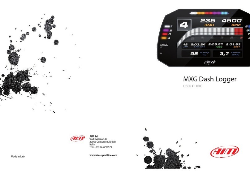
Aim MXL2 User manual

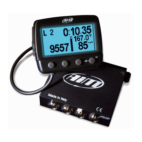
MXL2 Dash Logger
USER GU DE
1.02
MXL2 MANUALE ENG OK 2016. xp_Layout 1 28/10/16 14:36 Pagina 2

02
04
06
08
10
11
12
12
12
14
14
14
14
15
16
18
20
25
28
30
31
34
35
36
37
38
39
40
41
44
45
46
47
47
48
49
50
50
52
54
54
55
56
56
57
58
MXL2 Dash Logger
01 INTRODUCTION
02 WHAT IS IN THE KIT
03 LAYOUT AND PUSHBUTTONS
04 GEAR FLASHES AND ALAR LEDS
05 ECU CONNECTION
06 RP
6.1 RPM FROM ECU
6.2 RPM V A A 550 V SQUARE WAVE S GNAL OR CO L 150400V
07 SPEED
7.1 SPEED READ FROM THE ECU
7.2 SPEED READ FROM THE GPS RECE VER
7.3 SPEED READ FROM WHEEL SENSOR
08 ANALOG INPUTS
09 DIGITAL OUTPUTS
10 WIFI CONFIGURATION
10.1 CONF GUR NG YOUR DEV CE AS AN AP
10.2 JO N NG YOUR MXL2 TO AN EX ST NG NETWORK
10.3 H GH PERFORMANCE WLAN SETUP
10.4 ABOUT NTERNET CONNECT V TY
10.5 WORK NG W TH MACTM OS AND V RTUAL ZED W NDOWS TM
11 RACESTUDIO3 SOFTWARE
11.1 CONF GURAT ON
11.1.1 CHANNELS CONF GURAT ON
11.1.2 ECU STREAM CONF GURAT ON
11.1.3 CAN2 STREAM
11.1.4 MATH CHANNELS
11.1.5 PARAMETERS
11.1.6 SH FT L GHTS, ALARMS AND OUTPUT S GNALS
11.1.7 D SPLAY CONF GURAT ON
11.1.8 CAN OUTPUT
11.2 MOD FY OR DELETE AN EX ST NG CONF GURAT ON
11.3 CONNECT YOUR SYSTEM TO A PC
11.3.1 CONF GURAT ON TRANSM SS ON
11.3.2 L VE MEASURES AND CAL BRAT ON
11.3.3 DATA DOWNLOAD
12 GPS AND TRACK ANAGE ENT
12.1 TRACKS FEATURE
12.2 TRACKS COLLECT ONS
12.3 HOW TO MOD FY TRACK DATA N THE PC DATABASE
12.4 HOW TO DELETE A TRACK FROM THE PC DATABASE
12.5 HOW TO TRANSM T TRACK NFORMAT ON TO THE SYSTEM
13 DATA RECALL
14 EXPANSIONS
15 XL2 PINOUT
16 TECHNICAL DRAWINGS
MXL2 MANUALE ENG OK 2016. xp_Layout 1 28/10/16 14:36 Pagina 3

Thanks.
Dear Customer,
First, we would like to thank you for choosing
the MXL2 dash logger as the tool for
improving your racing craft setup and
on-track performances.
The MXL2, with its high contrast display,
advanced expansions and sampling
capabilities, gives you the flexibility for
reviewing your data in your preferred way
and recording them from a variety of
sensors and sources.
Please, before digging into your new data
system, keep in mind that we are constantly
working on bettering our software and
firmware.
So, be sure to check our website
periodically for any updates.
www.aim-sportline.com
03
MXL2 MANUALE ENG OK 2016. xp_Layout 1 28/10/16 14:36 Pagina 4

CHAPTER 1
04
What is XL2?
Which data does it
manage?
MXL2 is a color, high-contrast brilliant
traditional LCD dash logger developed
for race car installations.
t is fully customer configurable.
You can configure alarm LEDs
choosing color, blinking frequency and
defining the logic for turning them on
or off.
You can use a WiFi connection for
transmitting the data of your test,
sending data online and for
configuring the system.
Yes, MXL is used to produce data in
.DRK format. MXL2 offers an improved
data management and produces .XRK
format that only RaceStudio3 can read.
Nevertheless, the last releases of
RaceStudio2 can detect .XRK files and
transform them into old .DRK files that
are compatible with MXL1 and EVO4
files.
Data come from a wide range of sources,
including your vehicle ECU, the internal
accelerometers and gyro, the GPS
module included in the kit, the
analog/digital inputs, the external
expansions as well as predefined math
channels.
You can choose among a wide library of
page styles, defining the data to be
shown. Also end of scales and units of
measure can be easily configured, using
the Race Studio 3 software, included in
the kit.
Is it possible to configure
the pages?
You can define up to eight different
fully customizable pages.
How many pages does
it show?
How do alarm LEDs
work?
What is it possible with
WiFi?
Are the data recorded
by XL2 compatible
with the old
XL/EVO4 data?
MXL2 MANUALE ENG OK 2016. xp_Layout 1 28/10/16 14:36 Pagina 5

05
.XRK, taking advantage of GPS
technology, associates absolute time
and GPS position to each data with the
precision of 1 millisecond.
n this way, it is possible to better
compare different laps and tests.
Race Studio 3 is the new software for
managing configuration, data
download and data analysis for all the
future AiM systems.
t is going to substitute Race Studio 2,
which has accompanied us for almost
15 years.
Based on a totally new and much more
flexible architecture, it is a work in
progress as some features are conti-
nuously improved.
We are going to upgrade it very often,
What is the difference
between the old .DRK
format and new .XRK?
What about
Race Studio 3?
What are the
differences between
the old .DRK format
and new .XRK?
INTRODUCTION XL2
so, please, don’t forget to check our
web site at www.aim-sportline.com.
MXL2 MANUALE ENG OK 2016. xp_Layout 1 28/10/16 14:36 Pagina 6

CHAPTER 2
06
Harness
2. What is in the kit
MXL2 dash logger
The MXL2 kit includes:
GPS08 Module Software
MXL2 MANUALE ENG OK 2016. xp_Layout 1 28/10/16 14:36 Pagina 7

WHAT IS IN THE KIT XL2
MXL2 MANUALE ENG OK 2016. xp_Layout 1 28/10/16 14:36 Pagina 8

CHAPTER 3
08
Configurable Alarm LEDs 1-3 Configurable Alarm LEDs 4-6Shift Lights
MXL2 Dash Logger
ultifunctional Pushbuttons
MXL2 MANUALE ENG OK 2016. xp_Layout 1 28/10/16 14:36 Pagina 9

09
otorsport Connectors
Aluminum Body
-6
LAYOUT AND PUSHBUTTONS XL2
MXL2 MANUALE ENG OK 2016. xp_Layout 1 28/10/16 14:36 Pagina 10

4. Gear Flashes and Alarm LEDs
The system features 10 RGB gear flash LEDs
that can be freely configured in a very fle-
xible way. For each LED, you can define the
CHAPTER 4 GEAR FLASHES AND ALAR LEDS
10
The system has 6 different alarm LEDs too,
that you can configure in order to turn
them on or off depending on the value of
the analog or digital inputs, ECU values, ex-
pansion values, GPS information or math
channels.
You can associate an alarm LED, a message
and a digital output with each event.
RPM value that turns it on and the colour.
You can also define different RPM values of
each gear number.
You can configure them in order to be
turned off when the condition disappears,
when you push a pushbutton, when the test is
finished or when the data are downloaded
after the test.
Please refer to the related paragraph in order
to see how to manage gear flashes and alarm
LEDs.
2 2
1
1
2
MXL2 MANUALE ENG OK 2016. xp_Layout 1 28/10/16 14:36 Pagina 11

CHAPTER 5 ECU CONNECTION
11
XL2
The steps to manage the data coming from
the ECU are the following:
1. Determine which hardware connection
is available for your ECU.
2. Read the documentation about your ECU
at www.aim-sportline.com and identify the
name of the proper software driver to be
specified.
3. Using Race Studio 3, configure the
system setting your ECU driver with the
menu shown here below, that appears
when you create a new configuration.
The ECU has to be set when configuring
your system with RS3 configuration soft-
ware. The steps are explained in the related
section.
5. ECU connection
The system can acquire data from the ECU
of your vehicle. The list of the available ECU
protocols is published on our site:
www.aim-sportline.com/download area,
ECU connections.
This list includes more than 1000 different
protocols and is constantly updated with
new protocols.
When possible documents explaining how
to configure your ECU to ensure compati-
bility between the data flow transmitted
are available, too.
From an hardware point of view, the system
is compatible with all currently available
connections: CAN, RS232 or K Line.
MXL2 MANUALE ENG OK 2016. xp_Layout 1 28/10/16 14:36 Pagina 12

CHAPTER 6
12
6. RP
The system can receive the RPM signal from three different sources:
n from ECU
n through a square wave signal (8 to 50 V)
n from the low voltage (from 150 to 400 V) of the coil
6.1 RP from ECU
To get RPM from the ECU, please configure your device and enable RPM channel. RPM is one
of the many data flowing from your ECU.
6.2 RP via a 5-50 V square wave signal or coil (150-400 V)
n case your engine is not managed by any ECU, the device can read the signal from the low
voltage of the coil (whose peak can be from 150 to 400 V) or from a possible square wave (the
peak can be from 5 to 50V). The pin labelled "RP " reported in appendix “Pinout” receives
the signal:
The image shows an example of wiring for the ignition system.
The output, labelled “GRAY TACH” gives a 5-50V output that can be directly acquired. f the
output is not available from the ignition system, the system has to be connected to the low
voltage of the coil, as shown in the following schematic.
MXL2 MANUALE ENG OK 2016. xp_Layout 1 28/10/16 14:36 Pagina 13

RP
13
XL2
Point 1: low voltage of the coil
Point 2: connected to the spark plug
Point 3: connected to the +12V of the battery
After connecting the RPM signal, please use the software Race Studio 3 for enabling
the RPM channel.
1
2
3
1
2
3
MXL2 MANUALE ENG OK 2016. xp_Layout 1 28/10/16 14:36 Pagina 14

7.3 Speed read from wheel sensors
MXL2 has four wheel speed inputs, one in
the 37 pins connector and the other three
in the 22 pins connector.
The digital sensor X02SNVM00 detects the
presence of a metallic tooth placed at a
distance between 0.5 and 2 mm.
Please use the software RaceStudio3 to
load the sensor in the system configuration.
Just enter the program configuration panel
and, after enabling the desired speed
channels, set the wheel circumference and
the number of pulses per revolution.
7. Speed
The system can receive the speed signal
from three different sources:
n from the ECU
n from the GPS receiver included in the kit
n from the wheel sensors
(digital channels)
t is therefore possible to receive and store
different values of speed at the same time;
the more powerful ECUs
transmit up to four wheel speed values.
7.1 Speed read from the ECU
f your ECU sends the value of speed in its
data stream, it is obviously possible to read,
record and show that value.
Simply enable it using RaceStudio3
software when setting the channels.
7.2 Speed read from the GPS receiver
The GPS receiver you find in the kit
is configured in order to obtain the best
performance in term of reactivity and
accuracy.
For getting GPS speed you don't need any
configuration.
Simply connect the GPS08 Module to your
system and after a setup period of some
seconds the data will be received and
automatically recorded.
CHAPTER 7
14
MXL2 MANUALE ENG OK 2016. xp_Layout 1 28/10/16 14:36 Pagina 15

SPEED
15
XL2
8. Analog inputs
MXL2 has 8 analog inputs, recorded up to
1000 times per second each.
You can connect:
n 0-5 Volt signals
n ratiometric potentiometers
n pressure sensors
n thermo-resistances
n K-type thermocouples
Please follow these steps, using the
software RaceStudio3 to set the channels:
n connect the sensor to the desired input
n enable the channel in the Channels table
n select the proper sensor type; sensors of
many different types are properly handled
n set the sampling frequency
n set the unit of measure.
MXL2 MANUALE ENG OK 2016. xp_Layout 1 28/10/16 14:36 Pagina 16

16
CHAPTER 9 DIGITAL OUTPUTS
The system features two digital inputs on
the 22 pins connector.
Each of them can give an output of 1 amp
at 12 volts.
9. Digital outputs
Connecting examples
The digital output (Dout) is a LOW-S DE
type with internal 10 Kohm weak pull-up
resistor.
Here below are some connecting examples.
MXL2 MANUALE ENG OK 2016. xp_Layout 1 28/10/16 14:36 Pagina 17

17
XL2
You can configure them in order to turn
them on or off depending on the value of
the analog or digital inputs, ECU values,
expansions values, GPS information or
math channels.
To each event you can associate an alarm
LED, a message and a digital output.
You can configure it in order to turn them
off when the condition disappears, when
you turn the system off, when you push a
pushbutton or when the data are
downloaded.
Please refer to the related section in order
to see how to use RaceStudio3 to manage
the Output Signals.
MXL2 MANUALE ENG OK 2016. xp_Layout 1 28/10/16 14:36 Pagina 18

CHAPTER 10
18
10. WiFi Configuration
WiFi connectivity is set on AUTO by default. This means that if the vehicle is stopped WiFi is on
and goes OFF as the vehicle speed increases. Your system can be configured for WiFi commu-
nication in one of two ways.
1) As an Access Point (AP)
This is ideal when you have one device and one computer.
n this configuration your AiM device creates its own WiFi network, which acts as an AP to
which you can connect your PC.
MXL2 MANUALE ENG OK 2016. xp_Layout 1 28/10/16 14:36 Pagina 19

WIFI CONFIGURATION
19
XL2
n WLAN mode there are two layers of security available:
n network authentication: the network password
n device authentication: a unique device password
Using both network and device authentication allows for various security strategies where
multiple people, PCs and AiM devices are involved. For example a PC on a WLAN may see se-
veral AiM devices but can only communicate with AiM devices for which it has the password.
2) To join an existing Wireless Local Area Network (WLAN)
This is more complex and requires an external AP but is more flexible and powerful. n this way
you can communicate with more than one PC on the same network.
n this configuration both your device and your PC have to join a pre-existing WiFi network,
called WLAN, in order to communicate with one another. The network is now created by a net-
work device, which is acting as an external AP by permitting the device connectivity.
MXL2 MANUALE ENG OK 2016. xp_Layout 1 28/10/16 14:36 Pagina 20

20
CHAPTER 10
Follow these steps to create an AP, allowing
you to connect your PC to the device via
WiFi.
This is the most simple and direct WiFi con-
nection method and is ideal when you wish
to communicate with only one device
using one PC.
By default AiM system is configured as an
Access Point and creates a network without
a password completely accessible to eve-
ryone.
So, for establishing the WiFi connection:
nbe sure your AiM system has the WiFi
enabled.
nread its name in the lower part of the
Live Measures page.
nclick the WiFi icon of RaceStudio3 and
select your AiM system.
10.1 Configuring your device as an AP
MXL2 MANUALE ENG OK 2016. xp_Layout 1 28/10/16 14:36 Pagina 21
Table of contents
Other Aim Data Logger manuals
Popular Data Logger manuals by other brands

Dickson
Dickson PR125 USER MANUAL & PRODUCT GUIDE

MadgeTech
MadgeTech TSR101 Series Product Information Card

Omega
Omega OM-DLAV instructions

Ingersoll-Rand
Ingersoll-Rand Thermo King TouchPrint Series installation manual

Crane
Crane IQVu quick start guide

MadgeTech
MadgeTech MadgeNET RFTemp2000A Product user guide