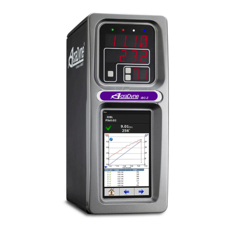
Aimco iEC User manual

AcraDyne
iEC DC Tool Controllers
User Guide

2
Thank you for your purchase of an AcraDyne iEC DC Tool Controller from AIMCO. The iEC represents
the most advanced controller for AcraDyne series electric controlled assembly tools and is capable
interfacing with all series of AcraDyne tools.
This manual is designed to provide the user of the AcraDyne iEC Controller with a guide to
understanding the features and functions of the controller. Programming this controller using
AcraDyne’s ToolWare software package provides a broad range of operating choices to tackle the most
difficult assembly projects with ease. Statistical analysis, communication and system diagnostic
features are also built in.
For more detailed programming, data analysis and system monitoring information please refer to the
AcraDyne ToolWare Operations section at the back of this manual.
For additional service and support, please contact your AIMCO distributor or contact AIMCO
at 1-800-852-1368 between the hours of 7:00 AM—4:00 PM Pacific Time.
Table of Contents
Safety Information ···········································································3
Front Panel Diagram (Figure 1) ·························································4
Bottom Panel Diagram (Figure 2) ······················································4
Top Panel Diagram (Figure 3) ···························································4
Main Display Panel Diagram (Figure 4) ··············································5
Dimensions ····················································································5
Initial Setup ···················································································6
Main Display Functions
Changing Parameter Sets ······················································8
Programming the Display Options (Steps 1-3) ··························8
Display Optional Values for Individual Rundowns (Steps 1-2) ·····10
Using the Optional Keypad Display Module (KDM)
KDM Diagram ·······································································11
Parameter Set Terms·····························································11
Turning the KDM On / Off·······················································12
Main Menu: 1) Parameter Setup
Setting Up Parameter Sets ··········································12
Accessing Quick Start Parameter Sets··························13
Editing Quick Start Parameter Sets ······························13
Configuring New Quick Start Parameter Sets·················14
Configuring a Complete Parameter Set ·························
Entering / Editing Values in the KDM ····························15
Main Menu: 2) Calibration ······················································16
Main Menu: 3) Administration Functions
Parameter Set Defaults ···············································17
Security ····································································18
Tool Information ························································19
Reset Factory Defaults ···············································19
Error Codes ······························································20
Filter Frequency ························································20
Adaptive Control························································21
Networking ·····················································································22
Error Proofing·················································································33
Appendix A Error Codes and Descriptions ·····································34
Appendix B Menu Structures of KDM ·············································35
Appendix C I/O Diagram & Definitions············································37
Appendix D Light Assignment for Light Tower and Key Bypass ········41
Appendix E Dual Trigger Lever Functionality for Gen 3-4 tools··········41
Appendix F TUBE NUT Homing Sequence ······································42
Appendix G Frequently Asked Questions ·······································43
Appendix H Toolware Users Guide - Separate Table of Contents ·······45
Introduction
3
SAFETY REQUIREMENTS
READ AND SAVE THESE INSTRUCTIONS
WARNING!
Ensure that owner/operator has read all Safety Requirements and User Manuals prior to operating.
To avoid electric shock, which may result in personal injury and/or death, electrical supply must be
meet the electrical requirements.
Do not operate power tools in explosive atmospheres, such as the presence of flammable
liquids, gases or dust.
To avoid electric shock, which may result in personal injury and/or death, electrical connections
must be properly grounded.
To avoid electric shock, which may result in personal injury and/or death, electrical wiring between
the device, electrical supply and any peripheral equipment must be routed in a secure manner.
Switch device to the “OFF” position and disconnect from any power supply prior to servicing. Lock
Out/Tag Out procedures should be followed.
To avoid electric shock, which may result in personal injury and/or death, cords should be kept from
heat, sharp edges, or any other potentially hazardous conditions.
When operating a power tool outdoors, use an extension cord suitable for outdoor use.
Keep out of reach of children.
DANGER!
Contact with water, solvents, or other liquid substances may result in personal injury and/or death.
Do not operate equipment under the influence of drugs, alcohol or circumstances in which you are
not fully alert.
Use safety equipment. Always wear eye protection.
Ensure the switch is in the off-position before plugging in.
Remove any adjusting key or wrench before turning the power tool on.
Do not wear loose clothing or jewelry. Keep hair, clothing and gloves away from
moving parts.
POWER TOOL USE AND CARE
Do not force the power tool. Use the correct power tool for your application.
Do not use the power tool if the power switch does not turn it on and off.
Safety Information

4
Front Panel
Top Panel
Figure 1
Figure 3
1—Main Display Panel—Annunciation and Display programming (see Page 5 for detail)
2— Power Disconnect Switch— Turns controller on and off
3—Keypad Display Module (KDM)—Onboard Interface for setup and programming (Optional)
Bottom Panel
Figure 2
1—CAN Connectors— For connection of AEC-CIM communication module and peripheral devices
2—System Connector (DB-15 Pin)— For upgrading / changing controller firmware
3—External transducer Connector (DB-25 Pin)— Non active, future feature
4— External I/O Connector (DB-25 Pin)— Input and output of signals for process control
5—Power Cord Connection— IPC-29 Connector
6—Ethernet Connection Access / Light Tower Board Connection/ Bottom Exit Tool Connection (Optional)
7—RS232 Connection (DB-9 Pin)— Serial-data output for communication with peripherals such as bar code
readers
i E C
7
6
5
4
3
2
1
1—Tool Connector (26 Pin) —Standard connection point for tool cable
2—Serial data connection for peripherals
3—Ethernet connection port (2nd connection optional with advanced communication packages)
4—Serial data connection for peripherals
1
23
4

5
Figure 4
Main Display Panel
1—Rundown Feedback Indicators
A—ACCEPT— Green LED indicates OK rundown
B—TORQUE—Steady red indicates HI, flashing red indicates LO
C—ANGLE—Steady yellow indicates HI, flashing yellow indicates LO
D—CYCLE—Blue LED indicates tool is in rundown cycle
2—Primary Display Field—Displays Parameter Set Target or Rundown torque
3—Secondary Display Field—Selectable Display Choices (Angle etc…)
4—Programmable Display Selection Buttons
A—Optional Display Access—Accesses the Programmable Options menu
B—NEXT—Scrolls through the different display options for the Secondary Display
C—SET—Sets the selected display option in the Secondary Display
5—CHANGE PSET—Scrolls upwards through programmed Parameter Sets
6—PSET Indicator—displays PSET that is currently operating
7—IR PORT ENABLED—Future function, not currently enabled
Dimensions
1
2
3
7
6
5
4
ABC
ABCD
Inches / Millimeters

6
INITIAL SETUP
Step 1
Connect the tool cable to the Tool Connection (Figure 3, pg. 4). The cable consists of a male pinset
housed in a molded connection with a notch or a 26-Pin male connector with two opposing locating pins.
Align the notch of the tool cable with the notch of the connector or the male and female locating-pins
and insert the cable. Next, securely thread the connector cover to the controller body.
Step 2
Repeat the above process to connect the cable to the AcraDyne tool that will be used with the controller.
AcraDyne pistol-style tools manufactured prior to January 2011 are hard–wired on the tool side and re-
quire no additional connection.
Step 3
Plug the female end of the power cable into the Power Cable connection (Figure 2, pg. 4).
Step 4
Plug the male end of the power cable into the appropriate power source.
Due to the variety of 220V power outlets worldwide, the standard power cable plug-end provided with
the controller may need to be modified to connect to local 220V power outlets.
The iEC Controller is designed to work with either a 110V or 220V input supply. When operating a
3000 series tool on 120V, the maximum speed of the tool is ½ of its catalog speed. Since speed
parameters are set as a percentage of maximum, the actual speeds of these tools run on 110V
will be ½ of the speed run on 220V.
Step 5
Turn the controller on by rotating the Power Disconnect Switch (Figure 1, pg. 4), to the POWER ON
position, represented by the I symbol.
When an iEC with SCC code 2.0 and higher is powered on, three messages will be shown on the dis-
play:
SYS INIT- indicates the system is initializing
IEC “#.##” - indicates the firmware version that is operating in the controller
SERVO FIRMWARE (A or B) — indicates the firmware of the controller’s servo module
These messages are normal and will clear as the system finishes initializing.
!
!

7
If the controller is powered on without a tool connected the following message will be shown on the
display:
AUT FLT 129
This message is normal and will clear once a tool is connected
Step 6
To turn the controller off, rotate the Power Disconnect Switch to the POWER OFF position, represented
by the 0 symbol
To reboot the controller without turning off the Power Disconnect, press and hold the
buttons simultaneously for 3 seconds.
Factory & Default Parameter Sets
Before the user programs the iEC controller for the first time, or after resetting the controller to factory
default settings, one of three different groups of parameters may be present in the controller:
DEFAULT WITH NO TOOL CONNECTED—These parameters will start at 10 Nm and increase
up to 80 Nm in increments of 10 Nm
DEFAULT WITH TOOL CONNECTED—This will create a group of 3 individual parameter sets,
one each at 30%, 60% and 80% of the connected tools maximum torque capacity
TEST PARAMETER SETS—Because every AcraDyne iEC controller is tested before being
shipped, some parameter sets that were used in this testing may be present in the controller.
If a parameter set is selected that has a target torque above the maximum capability of the tool,
the following message will be shown on the display
EXT FLT 4096
This message will clear when an allowable parameter set is selected or when the out-of-range
parameter set is reprogrammed to be within the capabilities of the tool.
!
!
INITIAL SETUP
+
!

8
Changing Parameter Sets
To change the parameter set that is active, press the CHANGE PSET button (Fig. 4) until the desired
parameter set number is displayed.
With each separate press of the button the parameter set numeral will advance upwards through the
highest parameter set that is programmed and then cycle back to parameter set #1. A maximum of 8
parameter sets can be programmed into the iEC controller.
The display for each type of strategy will vary. The main control parameter (Torque, Angle or both) will be
displayed when the Parameter Set is selected. The different strategies will display as follows:
Note: SCC Firm- ware Version 3.00 extends
the number of parameter sets that can be
programmed to 32. The extended parameter sets can be programmed via Toolware 3.0 or greater. For parameter sets 10 -32, the
numeric Pset LED will flash the first digit, then the second followed by a pause. If any of the parameter sets are “Linked”, the
CHANGE PSET button will automatically skip to the first Pset of the Linked Pset group. (For information on Linked parameter sets,
see the Setting Parameters section in the ToolWare portion of the user manual.)
Programming the Display Options
The Programmable Display Options feature in the iEC allows the user to select the information that will be
displayed in the Secondary Display Field.
Step 1
Press the DISPLAY OPTIONS button (Fig. 4) to access the Display Options Menu.
Immediately a message will appear in the Primary Display Field (Fig. 4) that will indicate which display
option is currently selected.
If no rundowns have been conducted since the most recent Power-On of the controller, the Secondary
Display Field will display the default information relating to the current display option.
If rundowns have been conducted since the controller was last Powered-On, then the Secondary Display
Field will display the value for that option pertaining to the most recent rundown in the current parameter
set.
!
Example: PSET #2, Torque Control
Strategy, 25 ft-lb Target
Example: PSET #3, Angle Control
Strategy, 270 Degree Target
ALTERNATING
Example: PSET #4, Torque Control / Angle Control Strategy,
25 ft-lb Target, 270 Degree Target
Main Display Functions

9
Step 2
To scroll through the available display options, press and release the NEXT button. Repeated presses
will cycle the display options as follows
DFLT > ANGL > BCNT > TOT > OK > NOK > CP > CPK > JTRT
The definition of each Display Option is as follows:
DFLT (Default) Field is blank if a Torque Control Strategy is programmed.
For all other strategies the field will display the angle of
rotation from Threshold to Final Torque
ANGL (Angle) If selected, field will display angle of rotation for the previous
rundown, regardless of strategy for the parameter set
BCNT (Batch Count) Field will display the batch count information for the selected
parameter set. Displayed values are current count
(cc) and batch total (bt), with the information displayed as
cc.bt.
TOT (Total Count) Value shows the total number of rundowns for all
parameter sets from midnight to midnight
OK (OK Count) Value shows the total number of acceptable rundowns for
all parameter sets from midnight to midnight
NOK (NOT OK Count) Value shows the total number of unacceptable rundowns
for all parameter sets from midnight to midnight
CP (Cp Value) Statistical value is Cp for selected parameter set
based on collection of programmed-minimum number of
rundowns. This value is reset upon controller initialization
or new Parameter Set Download or Tool Change
CPK (Cpk Value) Statistical value is Cpk for selected parameter set
based on collection of programmed-minimum number of
rundowns. This value is reset upon controller initialization
or new Parameter Set Download or Tool Change
JTRT (Joint Rate) Displays joint rate of selected Parameter Set based on
previous rundown. The value is displayed in degrees of
rotation from the Joint Rate Threshold (not Parameter Set
Threshold) to final torque. By default, the Joint Rate Threshold is
10% of target torque
Main Display Functions

10
Step 3
When the desired Display Option is selected, press the SET button (Fig. 4) to lock this option as the
visible display. Once the SET button is pressed, the display screens will clear. Upon completing a
rundown cycle, the value for the selected Display Option will be shown in the Secondary Display Field
(Fig. 4).
The selected Display Option will be displayed for all Parameter Sets.
Display Optional Values for Individual Rundowns
By scrolling through the Display Options after a rundown cycle, the value for each option can be quickly
viewed.
Step 1
Immediately after a rundown cycle, the selected Display Option will be shown in the Secondary Display
Field. To view a different Display Option value, press the NEXT button before conducting another
rundown.
Step 2
Continue to press the NEXT button to scroll though the available options. As each option is selected, the
corresponding value will be displayed in the Secondary Display Field.
The Display Option that is last shown before another rundown is conducted will be set as the
programmed display option.
To stop viewing the Display Option for the most recent rundown, simply conduct another rundown or
press CHANGE PSET to select a different parameter set.
!
!
Main Display Functions

11
Using the Optional Keypad Display Module (KDM)
1—KDM Display Screen
2—KDM Power On / Off Button
3—Shift Button—used to access alternate functions on highlighted buttons
4—SEND Button—Used to send new or edited parameter sets to the tool and controller
5—Numerical / Alternate Function keypad
Parameter Set Terms
ANGLE CONTROL / TORQUE MONITOR—Control strategy in which angle is the control parameter, but torque
is monitored.
ANGLE TARGET—Desired value for angle rotation; measured from threshold torque value.
AUTO-SET—Feature that allows manual entry of control parameters, but all others are determined by system defaults.
CYCLE COMPLETE—Torque level that determines the completion of a fastening cycle.
THRESHOLD—The torque value above which the system is, “in cycle” and data points are stored.
DOWNSHIFT TORQUE—Torque level at which the spindle changes from free speed to downshift speed.
ERGO MODE—Ramps the cut-off of power after reaching target torque, providing an ergonomic shutoff during a
hand-held tightening operation. (Can negatively effect cpk calculations)
HI LIMIT—The upper control limit for torque and/or angle.
LO LIMIT—The lower control limit for torque and/or angle. Must be set lower than target parameter. Any torque/angle low-
er than this value will be indicated by a yellow light and with a Lo Torque and/or Low Angle error on KDM.
RPM FREE—Spindle output speed at the beginning of a tightening cycle, entered as a percentage of maximum tool speed.
RPM DOWN—Spindle output speed after exceeding downshift torque; entered as a percentage of maximum tool speed.
SSTART—(Soft Start) Speed of output spindle ramps up at a programmable rate to RPM free speed; allows the operator
or system to engage the socket onto the fastener in a more controlled fashion.
TARGET TORQUE—Torque level which, when achieved, causes the power to the drive motor to be cut off.
TORQUE CONTROL—Control strategy in which torque is the only control parameter.
TORQUE CONTROL / ANGLE MONITOR—Control strategy in which torque is the control parameter, but rotational angle
is monitored. A valuable strategy for controlling torque while also checking for cross threaded or stripped fasteners.
4
3
2
1
5

12
Turning the KDM On
After turning on the iEC Controller (described in Initial Set-up, Pg. 6), press the POWER button on the KDM.
The following text will be shown on the KDM Display Screen:
Turning the KDM Off
1) Turning off the iEC Controller (detailed in Initial Set-up, Pg. 6)
2) Pressing the POWER button on the KDM for 2 seconds.
Note: The KDM does not support Psets above 8, Linked Psets, or Batch Control. These features are available via Toolware 3.0 or greater.
Main Menu: 1) Parameter Setup
Starting from the Main Menu, a variety of functions can be accessed through the KDM. Programming,
calibration, controller set-up, security set-up, and error analysis can all be achieved through properly using the
KDM. The following sections will detail the Menu Structure of the KDM and the various functions within each
area.
Setting Up Parameter Sets
This section will detail how to set up parameter (PSETS) sets for assembly by using the KDM.
There are two methods of programming a PSET—Quick Start or Configure.
QUICK START:
Quick Start Mode only requires the user to select the desired parameter set and target torque.
All other values are set according to the system defaults
(further explained in the ADMIN section—see Page 17).
CONFIGURE:
Configure Mode allows the operator to set up a new parameter set or edit all programmable operating
functions for an existing parameter set.
Using the Optional Keypad Display Module (KDM)
The Optional KDM allows for quick access to the IEC Control programming features. Not all
features are accessible by use of the KDM. For access to higher level features (i.e..Batch
Programming, Button Options, Linked PSet) please use a PC connected to the
controller and the ToolWare software interface program.

13
Accessing Quick Start Parameter Sets
From the MAIN MENU, press 1 for SETUP PSET
Press 1 for QUICK START
The following text will be displayed on the KDM display screen:
Choose from EDIT PSET or CONFIG PSET. See the following sections for instructions on editing or
configuring Quick Start parameter sets.
Editing Quick Start Parameter Sets
Depending on the number of Parameter Sets that have previously been programmed into the iEC Controller,
the user will have the option of choosing from 1 to 8 parameter sets to edit.
Press the number of the Parameter Set that is to be edited. The following text will be displayed on the KDM
display screen:
To change the target torque value in .1 unit increments press
To change the target torque value in 1.0 unit increments press
After the target torque is entered correctly, press
Verify that the correct parameter set is active by observing the PSET Indicator on the Main Display
Panel. If the desired parameter set is not active, press CHANGE PSET to cycle through the available
parameter sets until the appropriate set is displayed.
The tool is now ready to be run to the appropriate target torque value.
Using the Optional Keypad Display Module (KDM)
2
8
or
+2or +
8

14
Using the Optional Keypad Display Module (KDM)
Configuring New Quick Start Parameter Sets
Depending on the number of Parameter Sets that have previously been programmed into the iEC Controller, the
new parameter set will automatically be assigned a value from 2 through 8. Press the number on the KDM that
corresponds to the number for the next parameter set to be configured. For example, if the following text were to
be displayed in the Quick Start screen:
the user would press 4 on the key- pad to configure a new Quick Start Pset.
The following text will be displayed on the KDM display screen:
To change the target torque value in 0.1 unit increments press
To change the target torque value in 1.0 unit increments press
After the target torque is entered correctly, press
Verify that the correct parameter set is active by observing the PSET Indicator on the Main Display
Panel. If the desired parameter set is not active, press CHANGE PSET to cycle through the available parameter
sets until the appropriate set is displayed.
The tool is now ready to be run to the appropriate target torque value.
When exiting from Quick Start mode, all torque values are cleared from the KDM. Upon re-entering Quick Start
mode, target torque values for all parameters will be set to the value determined by applying the default
percentage to the tool that is connected to the controller.
Configuring a Complete Parameter Set
For a detailed explanation of each of the programmable functions within a parameter set see the list of key
terms in Parameter Set Terms on page 11.
From the MAIN MENU, press 1 for SETUP PSET
Press 2 for CONFIGURE
The following text will be displayed on the KDM display screen:
2
8
or
+2or +
8
!

15
Using the Optional Keypad Display Module (KDM)
Depending on the number of Parameter Sets that have previously been programmed into the iEC Controller, the
user will have the option of choosing from 1 to 8 parameter sets to edit. If the user chooses to configure a new
parameter, the next set will be assigned the next available PSet value, up to 8.
Press the button on the KDM corresponding to the PSET that will be edited or configured.
The following text will be displayed on the KDM display screen:
If editing a parameter set, the Control Strategy (definitions on page 11) of the PSET will be identified by
an asterisk.
Press the button on the KDM corresponding to the desired Control Strategy.
The following text will briefly be displayed on the KDM display screen:
followed by the following text:
The PS# text in the bottom-right cor- ner of the display is for the users reference
and identifies the PSET that is being configured or edited.
Entering / Editing Values in the KDM
The flashing cursor highlights which field can be changed. Two possibilities exist for entering values into a field,
depending on which function is being programmed:
For numeric values, press the appropriate key on the KDM.
For YES or NO entries, press
When an < and/or > symbol ap- pears in the upper-
right corner of the KDM display, this notifies the user that additional functions may be accessed by scrolling to
the previous or next page of text. To scroll to one of
these pages, press
!
+or +
YES NO
+4or +
6

16
Using the Optional Keypad Display Module (KDM)
To move to and modify the next or previous function, press
The cursor will then highlight the field that can be modified.
To clear a mistakenly entered value, press
When all functions have been modified appropriately, press
Verify that the correct parameter set is active by observing the PSET Indicator on the Main Display Panel. If the
desired parameter set is not active, press CHANGE PSET to cycle through the available parameter sets until
the appropriate set is displayed.
The tool is now ready to be run to the appropriate target torque value.
The AUTO-SET function is under development for future versions of the iEC controller.
If the user exits the CONFIGURE mode before pressing all edits and modifications that have been
entered will be lost and the entries will revert back to the previous value.
Main Menu: 2) Calibration
The Auto Cal is non functional for the user.
+2or +
8
!
!
+DEL

17
Main Menu: 3) Administration Functions
Parameter Set Defaults
Parameter set defaults are the values used to calculate control parameters when using either Quick Start
or Auto Set. This is also the area where units of measurement for all parameters is set.
To access the Parameter Set Default function:
From the MAIN MENU, press 3 for ADMIN
Press 1 for SETUP PSET
The following text will be displayed on the KDM display screen:
Navigation and value-entry is the same as described in the section Setting Up Parameter Sets
on pages 12—16.
All programmable default values are described below:
TQTARGET%: The default torque target shown when entering quick programming. The value entered is a
percentage of the maximum torque of the tool. For example, if the value entered is 80 and the maximum
torque of the tool is 30 Nm, the default target torque when entering quick programming will be 27.0 Nm.
TQ+/-%: The default percentage used for high and low torque limit. The value entered is a percentage
of target torque.
TQTHOLD%: The default torque threshold. The value entered is a percentage of target torque.
TQDSHIFT%: The default setting for torque downshift point. The value entered is a percentage
of target torque.
CYCCOMP%: The default setting for cycle complete torque. The value entered is a percentage
of target torque.
RPMFREE%: The default setting for RPM free speed. The value entered is a percentage of maximum output
speed in revolutions per minute (RPM). 3000 series AcraDyne tools operating at 120V will run at 1/2 of the
programmed speed.
RPMDOWN%: The default setting for spindle speed after crossing the downshift torque level. The value
entered is a percentage of maximum output spindle speed in revolutions per minute (RPM).
UNITS: The default engineering units for operation. The KDM is only capable of using one engineering unit for
all parameter sets. Changing the units in this section will affect all parameters sets.
Using the Optional Keypad Display Module (KDM)

18
Using the Optional Keypad Display Module (KDM)
Security
The security function allows the user to set up a password in order to prevent unauthorized persons
from altering the programming of the iEC controller. Once the password function is activated, the user
will be prompted to enter the correct password whenever attempting to navigate past the Main Menu.
If the user changes the password and then loses or forgets the new password, the Factory Default
password will still allow the user to access all menus and functions. Please call your AIMCO sales
representative for assistance in entering the Factory Default Password.
To access the ADMIN SECURITY function:
From the MAIN MENU, press 3 for ADMIN
Press 2 for SECURITY
The following text will be displayed on the KDM display screen:
If the password function is already enabled, the text will read 1) DISABLE PWORD
To activate the password function, press 1) ENABLE PWORD
To enter a new password, press 2) CHANGE PWORD
The following text will be displayed on the KDM display screen:
Enter a 4-digit password. Once the four digits are entered, the user will
automatically be prompted to con- firm the password.
When the correct password is confirmed, the following text will briefly be displayed on the KDM display
screen:
!

19
Using the Optional Keypad Display Module (KDM)
Tool Information
This section of the ADMIN menu provides the user with useful information regarding the tool that is
currently connected to the iEC controller. This information may be needed for reference when setting up
parameter sets or calibrating the tool.
The items that can be viewed in TOOL INFO are:
ID: The serial number for the tool
Tq: The maximum torque rating of the tool, in the units that are selected in PSET DEFAULTS
Speed: The maximum output-spindle speed of the tool in revolutions per minute (RPM)
CAL: The scaled value that correlates the voltage signal of the transducer to a torque value
To access the ADMIN SECURITY function:
From the MAIN MENU, press 3 for ADMIN
Press 3 for TOOL INFO
Reset Factory Defaults
The RESET DEFAULTS menu allows the user to quickly reset the iEC Controller setting to the original
factory default values.
The values that can be reset are:
1) TOOL CAL VALUE
2) LOGIC I/O
3) PARAMETER SETS
To access the RESET DEFAULTS MENU:
From the MAIN MENU, press 3 for ADMIN
Press 4 for RESET DEFAULTS (this choice can also be viewed by scrolling to the next text page to
view the additional ADMIN MENU options)
The following text will be displayed on the KDM display screen:
The user can then select the values to reset by pressing the corre-
sponding number on the keypad.

20
Using the Optional Keypad Display Module (KDM)
The user will be prompted to confirm the desire to reset values with the following text:
To select Y and confirm the desire to reset the values, press
To cancel the reset process, press
Error Codes
By default, the iEC Controller only displays Error Codes in the Primary and Secondary Display Fields of
the Main Display Panel (Figures 1 & 4). These errors will display automatically when recorded. Error
codes are listed in Appendix A in this users guide. For additional information on Error Codes contact
AcraDyne Technical Support or your AIMCO representative.
Filter Frequency
The Filter Frequency is non functional for the user.
+
YES
+
NO
Table of contents
Other Aimco Controllers manuals

Aimco
Aimco AcraDyne Gen IV iAC User manual

Aimco
Aimco ArcaDyne IEC4W User manual

Aimco
Aimco AcraDyne Gen IV Manual

Aimco
Aimco AcraDyne iPC User manual

Aimco
Aimco AcraDyne Gen IV User manual

Aimco
Aimco UEC-4800EX User manual

Aimco
Aimco AcraDyne Gen IV User manual

Aimco
Aimco AcraDyne iBC-Z User manual

Aimco
Aimco AcraDyne Parts list manual

Aimco
Aimco UEC-4800EPL User manual