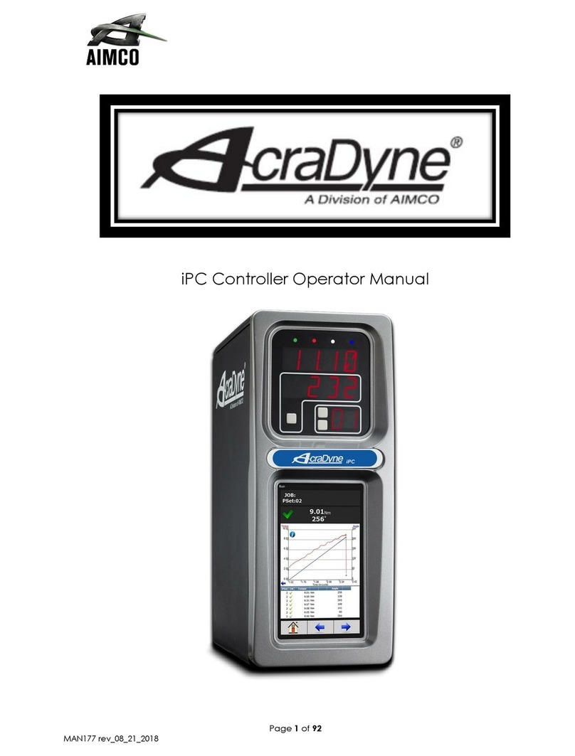
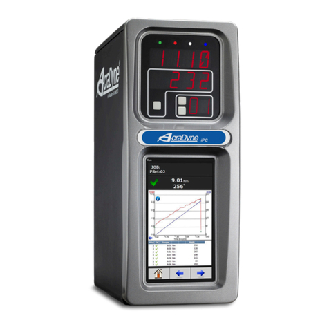
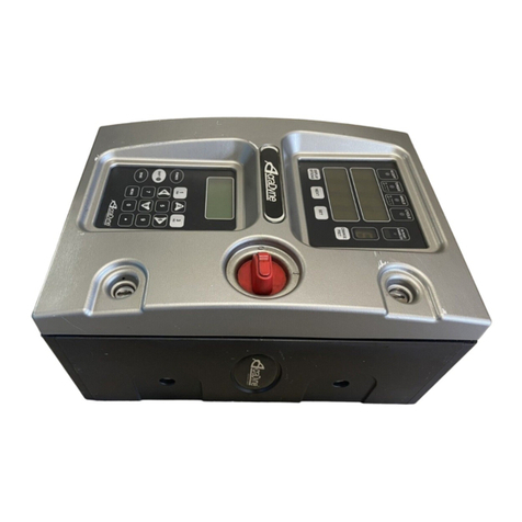
Aimco AcraDyne Gen IV User manual

Gen IV iPC Controller Operation Manual
10000 SE Pine St., Portland, OR 97216 • 800-852-1368 • 503-254-6600 • Fax 800-582-9015
www.aimco-global.com

2
AcraDyne Gen IV iPC Controller Manual
Table of Contents
1. Safety Information . . . . . . . . . . 3
2. Controller Diagram . . . . . . . . . . 4
2.1 Bottom Panel . . . . . . . . . . . 4
2.2 Front Console LED Display . . . . . . . 4
3. Initial Setup. . . . . . . . . . . . . 5
3.1 Connecting to the Controller . . . . . . 5
3.2 Quick Setup (Default PSets from Tool) . . . 7
4. Home Page (Main Menu) . . . . . . . . 8
4.1 Run . . . . . . . . . . . . . . 8
4.2 PSet . . . . . . . . . . . . . . 10
4.2.1 Add New PSet . . . . . . . . . 10
4.2.1.1 Add New Stage . . . . . . 10
4.2.2 PSet Stages . . . . . . . . . . 11
4.2.2.1 TC_PM Torque Control Pulse
Monitor. . . . . . . . . . 11
4.2.3 Edit PSet . . . . . . . . . . . 12
4.2.4 Advanced Options . . . . . . . 12
4.2.5 Manage PSets . . . . . . . . . 13
4.2.6 Multistage Rundown Evaluation and
Reporting . . . . . . . . . . . 14
4.3 Job . . . . . . . . . . . . . . 14
4.3.1 Add New Job . . . . . . . . . 14
4.3.2 Advanced Options . . . . . . . 15
4.3.3 Jobs "Enabled" Display and Button
Function . . . . . . . . . . . 15
4.4 Results . . . . . . . . . . . . . 16
4.4.1 Saving Rundown(s) . . . . . . . 16
4.5 Controller . . . . . . . . . . . . 17
4.5.1 Tool Setup . . . . . . . . . . 17
4.5.1.1 Tool Parameters . . . . . . 17
4.5.1.2 Disassembly . . . . . . . . 18
4.5.1.3 Lock Tool On Reject . . . . . 18
4.5.2 IO . . . . . . . . . . . . . 19
4.5.2.1 Physical IO . . . . . . . . 19
4.5.2.2 Physical IO Monitor . . . . . 19
4.5.2.3 Anybus/Modbus TCP/Ethernet IP
Inputs . . . . . . . . . . 20
4.5.2.4 Anybus/Modbus TCP/Ethernet IP
Outputs . . . . . . . . . 21
4.5.3 Communication Interfaces . . . . . 22
4.5.3.1 Ethernet . . . . . . . . . 22
4.5.3.2 Second Ethernet . . . . . . 22
4.5.3.3 System Port . . . . . . . . 22
4.5.3.4 Serial Port . . . . . . . . . 23
4.5.3.5 Anybus . . . . . . . . . 23
4.5.3.6 Serial USB . . . . . . . . . 23
4.5.4 Protocols . . . . . . . . . . . 25
4.5.5 Front Panel Buttons . . . . . . . 25
4.5.6 Power Up . . . . . . . . . . . 25
4.5.7 Bar Code Setup . . . . . . . . 25
4.5.8 Set Time . . . . . . . . . . . 26
4.5.9 Remote Connections . . . . . . . 26
4.5.10 Languages . . . . . . . . . . 26
4.6 Accessories . . . . . . . . . . . 27
4.7 Diagnostics . . . . . . . . . . . . 27
4.7.1 Controller Overview . . . . . . . 27
4.7.2 Controller Status . . . . . . . . 27
4.7.3 Live Tool Features . . . . . . . . 28
4.7.4 Tool Communications . . . . . . 28
4.7.5 Identify Controller . . . . . . . . 28
4.7.6 Record Logs . . . . . . . . . . 29
4.7.6.1 Change Log . . . . . . . 29
4.7.6.2 Information Log . . . . . . 29
4.7.6.3 Error Log . . . . . . . . . 29
4.7.6.4 All . . . . . . . . . . . 29
4.7.7 System Status . . . . . . . . . 29
4.7.8 I/O Diagnostics . . . . . . . . . 29
4.7.9 Network Diagnostics . . . . . . . 29
4.8 Login . . . . . . . . . . . . . . 30
4.9 Advanced . . . . . . . . . . . . 30
4.9.1 Login Setup . . . . . . . . . . 30
4.9.2 Results Archive . . . . . . . . . 31
4.9.3 Import Settings . . . . . . . . . 32
4.9.4 Export Controller . . . . . . . . 32
4.9.5 Update Controller . . . . . . . . 32
4.9.6 Backup Restore . . . . . . . . . 33
4.9.7 Restore Factory Defaults. . . . . . 33
4.9.8 Previous Software . . . . . . . . 34
4.9.9 Calibrate Touch Screen . . . . . . 34
4.9.10 Soft Reboot . . . . . . . . . . 34
5. Barcode Reader Details . . . . . . . . 35
6. Icons Defined . . . . . . . . . . . .37
6.1 Stop Codes . . . . . . . . . . . . 38
7. Error Codes. . . . . . . . . . . . . 39
8. 24 Volt I/O . . . . . . . . . . . . .40
9. Assignable I/O . . . . . . . . . . . 42
10. Controller Supported MIDs. . . . . . . . 54
11. Dimensions . . . . . . . . . . . . . 55
12. Specifications . . . . . . . . . . . .55
13. Troubleshooting . . . . . . . . . . . 56
14. AIMCO Warranty . . . . . . . . . . .58

3
AcraDyne Gen IV iPC Controller Manual
4. Power tool use and care
a. Do not force the power tool. Use the correct power
tool for your application.
b. Do not use the power tool if the switch does not
turn it on and off.
c. Disconnect the plug from the power source and/
or remove the battery pack, if detachable, from
the power tool before making any adjustments,
changing accessories, or storing power tools. Such
preventive safety measures reduce the risk of
starting the power tool accidentally.
d. Store idle power tools out of the reach of children
and do not allow persons unfamiliar with the power
tool or these instructions to operate the power
tool. Power tools are dangerous in the hands of
untrained users.
e. Maintain power tools and accessories. Check for
misalignment or binding of moving parts, breakage
of parts, and any other condition that may affect
the power tool's operation. If damaged, have the
power tool repaired before use. Many accidents
are caused by poorly maintained power tools.
f. Use the power tool, accessories, and tool bits, etc.,
in accordance with these instructions, taking into
account the working conditions and the work to
be performed. Use of the power tool for operations
different from those intended could result in a
hazardous situation.
g. Keep handles and grasping surfaces dry, clean,
and free from oil and grease. Slippery handles and
grasping surfaces do not allow for safe handling
and control of the tool in unexpected situations.
5. Service
a. Have your power tool serviced by a qualied repair
person using only identical replacement parts.
This will ensure that the safety of the power tool is
maintained.
6. Equipment Installation, Operation, and Maintenance
a. Safety of any system incorporating the equipment
is the resposibility of the system assembler
b. Position the equipment so that it is easy to access
the disconnecting device
c. Do not replace main power cord with an
inadequately rated cord
d. Only allow your power tool to be repaired by a
qualied technician using only original spare parts,
available from AIMCO. This ensures that the safety
of your device is maintained.
General Power Tool Safety Warnings
WARNING
Read all safety warnings, instructions, illustrations, and
specications provided with this power tool. Failure to follow
all instructions listed below may result in electric shock, re,
and/or serious injury.
Save all warnings and instructions for future reference.
1. Work area safety
a. Keep work area clean and well lit.
b. Do not operate power tools in explosive
atmospheres, such as in the presence of
ammable liquids, gases, or dust.
c. Keep children and bystanders away while
operating a power tool.
2. Electrical safety
a. Power tool plugs must match the outlet. Never
modify the plug in any way. Do not use any
adapter plugs with earthed (grounded) power
tools.
b. Avoid body contact with earthed or grounded
surfaces, such as pipes, radiators, ranges, and
refrigerators.
c. Do not expose power tools to rain or wet
conditions.
d. Do not abuse the cord. Never use the cord for
carrying, pulling, or unplugging the power tool.
Keep cord away from heat, oil, sharp edges, or
moving parts.
e. When operating a power tool outdoors, use an
extension cord suitable for outdoor use.
f. If operating a power tool in a damp location is
unavoidable, use a residual current device (RCD)
protected supply.
3. Personal safety
a. Stay alert, watch what you are doing, and use
common sense when operating a power tool. Do
not use a power tool while you are tired or under
the inuence of drugs, alcohol, or medication.
b. Use personal protective equipment. Always wear
eye protection.
c. Prevent unintentional starting. Ensure the switch is in
the off-position before connecting to power source
and/or battery pack, picking up or carrying the
tool.
d. Remove any adjusting key or wrench before
turning the power tool on.
e. Do not overreach. Keep proper footing and
balance at all times.
f. Dress properly. Do not wear loose clothing or
jewelry. Keep your hair, clothing, and gloves away
from moving parts.
g. Do not let familiarity gained from frequent use of
tools allow you to become complacent and ignore
tool safety principles. A careless action can cause
severe injury within a fraction of a second.
1. Safety Information
4
AcraDyne Gen IV iPC Controller Manual
2.1 Bottom Panel
1
3
2
49
8
6
7
2.2 Front Console LED Display
Indicator Lights
Green Indicates fastening cycle meets
specied parameters.
Red Indicates fastening cycle
rejected for exceeding high
torque.
Red
Flashing
Indicates low torque. Fastening
cycle was rejected for not
achieving low torque.
Yellow Indicates High Pulse. Fastening
cycle was rejected for
exceeding high pulse.
Yellow
Flashing
Indicates Low Pulse. Fastening
cycle was rejected for not
achieving low pulse.
Blue Tool is In-cycle, above
threshold.
Toggle Button
Toggles what
is shown in the
secondary display
Torque Display
Always displays torque value
Secondary Display
Toggle button switches secondary
display between
○Units of measure
○Ethernet 1 IP address
○Ethernet 2 IP address
○USB (System Port) IP address
○Angle report
NOTE: If Jobs are enabled refer to
"4.3 Job" on page 14 for Toggle
Button function.
Parameter Settings
(PSet)/Job Display
Increment/Decrement Buttons
Change PSet
1Tool Connection
2USB port-for import/export of data including
rmware updates
3Power Cord Connection
4Power Disconnect Switch-Turns controller on
and off.
5System Port- USB connection used to connect
external computer to congure/monitor the
controller.
6Ethernet Port RJ45: Connection used to
connect external computer to congure/
monitor the controller.
7Serial Port (DB-9 Pin M) Serial data Output
for communication with peripherals such as
barcode readers and printers
824 Volt I/O Connector (DB-25 Pin M): Input and
output of signals for process control.
9Anybus-To connect to customer’s eldbus
network (Ex: Probus)
AcraDyne Gen IV iEC Controller Manual
2. Controller Diagram
5

5
AcraDyne Gen IV iPC Controller Manual
Touchscreen Console
Controller functions and programming can be
accessed directly through the touch-screen.
1. Power on controller.
2. Run screen will appear
3. Controller is ready for use.
Connecting via the System Port Directly to PC
The following is an example using Window 7. Your
screen may look different depending on the
operating system.
Windows USB Setup
Step 1: Power on PC and controller, allow enough
time for them to become fully operational.
Step 2: Attach controller to PC using a USB 2.0 A-B
cable. If this is the rst time connecting the devices,
wait for Windows to install the RNDIS driver. This
should happen automatically.
Step 3: After the driver is installed, go to ‘Control
Panel’.
Step 1: Connect Sensor Cable to CN-1 Connector
of IPC Controller (Figure 1, pg. ) and connect
Amphenol Connector to the tool.
Step 2: Plug female end of power cable into Power
Cable Connector.
Step 3: Plug male end of power cable into
appropriate power source. Connection to local
power should be made in consultation with a
qualied electrician.
Step 4: The Secondary Protective Earth Attachment
(it is required) must be connected to ground using
the #14 AWG conductor, a green wire with a yellow
stripe. Attach using a #10-14AWG ring terminal and
#10 star washer (see Figure 1).
Figure 1 — Secondary Protective Earth Attachment
Step 5: Turn controller on by pushing the Power
Disconnect Switch to the POWER ON position, a light
indicates power on.
3.1 Connecting to the Controller
There are three ways to program/communicate with
the controller:
• Controller touch-screen console
• System Port: (USB A to B connection) Direct
connection to controller.
• Ethernet Port: Via direct connection or LAN.
3. Initial Setup

6
AcraDyne Gen IV iPC Controller Manual
Step 7: Find the Local Area Connection that is using
the ‘USB Ethernet/RNDIS Gadget’ network. Right
click this network and go to ‘Properties’.
Step 8: In Properties window select ‘Internet Protocol
Version 4’ and click ‘Properties’.
Step 9: In ‘Properties’, set the IP address to a static
address.
Type an IP address of 192.168.1.5 (Any address on
the same subnet as the controller will work). Set
subnet mask to 255.255.255.0
Step 10: To connect to the controller, open a
browser such as Chrome or Firefox. Enter 192.168.1.4,
the default system port IP address.
Step 4: Go to ‘Network and Internet’.
Step 5: Go to ‘Network and Sharing Center’.
Step 6: Go to ‘Change adapter settings’.

7
AcraDyne Gen IV iPC Controller Manual
To connect to the controller. In the Computer/Laptop
open a browser such as Chrome or Firefox. Enter
10.10.30.99, the default Ethernet port IP address.
You will see on your computer screen the controller
software
NOTE: Controller does not have a DHCP client, it
will not automatically congure itself with a usable
IP address. Consult your Network Administrator for
conguring a correct IP address for your network.
The PC, Laptop or Tablet IP address will need to be
congured to communicate with the controller.
3.2 Quick Setup (Default PSets from Tool)
On the Home Page press the following to accept
default PSet Parameters:
This will generate three generic PSets for the tool
connected to the controller. It will automatically
use the 40%, 60%, and 80% of the rated maximum
torque of the tool in a two-stage Torque Control Pulse
Monitor Strategy (TC_PM). A prompt will display rated
Max Torque and Max RPM of the connected tool
for reference. These Psets can be modied to meet
application requirements.
You will see the controller software on your
computer screen.
NOTE: Controller does not have a DHCP client, it
will not automatically congure itself with a usable
IP address. Consult your Network Administrator for
conguring a correct IP address for your network.
The PC, Laptop or Tablet IP address will need to be
congured to communicate with the controller.
Connecting using the Ethernet Port Directly or via
LAN to PC
Turn on the computer and make a physical
connection by using a straight through Ethernet cable.
Turn on controller. Verify the controller IP address in
‘Communication Interfaces’ or press toggle button
to verify the IP address. If defaulted 0.0.0.0 set
desired IP address.
Set a static IP address of the Computer/Laptop
to 10.10.30.98 (example) and subnet mask to
255.255.255.0. (For instructions, see the example in
"Step 9" earlier in this section.)

8
AcraDyne Gen IV iPC Controller Manual
Graph displays curves representing Torque (green
trace).
The blue left arrow at the origin of the graph will
change the X-axis of the rundown curve from Time
(In – Cycle) to Time (Overall) and Angle.
Below the graph is a historical table that will give
information and status of the most recent rundowns,
including current PSet, accepted/failed rundown
status,torque and angle.
Arrows allow user to scroll left or
right for viewing real time Job
information such as Run Screen or
rundown indicators.
Home tab will return user to the Home Page
Click for curve detail.
Click on blue arrow to change curve X axis.
Choose Time In-cycle or Time Overall screen.
Run Screen displays real time Job information.
4.1 Run
The Run Screen is essentially the dashboard of the
Gen IV controller and provides a look at real-time
information regarding rundowns.
Time (In-Cycle) Screen
Indicates the current JOB.
Indicates the current PSet in which you are
operating.
Indicates accepted rundown.
Indicates failed rundown.
Displays Torque and Angle for current
rundown.
Number of Pulses
4. Home Page (Main Menu)

9
AcraDyne Gen IV iPC Controller Manual
Example of Accepted Job
Example of Failed Job
Large Screen Indicators and Audit information
The large screen indicators are helpful in viewing real time results of the rundown from a distance.

10
AcraDyne Gen IV iPC Controller Manual
Time Limit(s): Maximum allowable time (in seconds)
tool is allowed to run.
Advanced Options: (see "4.2.4 Advanced Options"
on page 12)
Once PSet values are entered press to enter
Edit Stage screen (shown in the following section).
4.2.1.1 Add New Stage
A single stage or multiple stages build a PSet. Up to
20 stages can be assigned per PSet.
The following stage option is available:
Once the desired stage(s) are selected and
congured, press to save stage and again to
save the PSet and return to initial PSet menu.
Next Press to go to the RUN screen or to
return to the Home page. The tool should now be
operational and you are ready to run a congured
PSet.
4.2 PSet
Parameter Settings (PSets) control the fastening
process. The following describes the different
fastening strategies and how to setup the basic PSet
parameters necessary to perform a fastening. Up to
256 PSets are available.
4.2.1 Add New PSet
On Home Page press the tab.
On PSets screen press to add a new Pset.
Add a PSet
Edit a PSet
Coy a PSet
Delete a PSet
Default PSets (See "3.2 Quick Setup" on page 7)
Manage (see "4.2.5 Manage PSets" on page 13)
On Add New PSet screen (below) enter appropriate
values.
PSet Number: Current
PSet to be added.
Torque Units: Unit of
measure.
In Cycle Torque:
Threshold value at
which tool is “In Cycle”
and results from the
Rundown will be
reported.
Speed: This is the tool
output speed in RPM
after in-cycle torque

11
AcraDyne Gen IV iPC Controller Manual
4.2.2 PSet Stages
4.2.2.1 TC_PM Torque Control Pulse Monitor
Torque High: Upper control limit of the rundown.
Torque Target: Final desired torque (CUT Level).
Torque Low: The lower control limit of the rundown.
Pulse Bailout: Total number of pulses never to be exceeded. Helps to
illustrate how far past Pulse High the rundown experienced without
damaging the part or excessively wearing the tool’s pulse uid.
Pulse High: Maximum acceptable pulses
Pulse Low: Minimum acceptable pulses
Pulse Reference: (drop down menu)
• In-cycle Pulse: Monitoring number of tool Pulse begins after the tool
overcomes pre-set in-cycle Torque
• Stage Pulse: Monitoring all Pulses specically in the Stage
Additional Pulses: After reaching target torque, additional pulses to be
applied before shutting of the air to the tool.

12
AcraDyne Gen IV iPC Controller Manual
If further Stage changes are needed click the
Edit button again to enter Edit Stage screen
(below).
Once desired changes are made click twice to
save changes.
4.2.4 Advanced Options
PSet Name: Add
PSet name if
desired (up to 10
characters).
Judgement
Delay: Tool
provides
judgment
after tool stops
producing
pulses and this
delay expires.
Pulse Timeout:
After in-cycle is
reached the tool
will stop running
and end the
fastening if the
time between
pulses exceeds this value
Initial Current (%): Percentage of maximum
current delivered to the motor before in-cycle
torque threshold. Reduce this value to reduce the
amplitude of torque pulses.
4.2.3 Edit PSet
On Home page press
On the PSet
screen click on
the desired PSet
you would like to
edit.
Click on the Edit button to make changes in the
Edit screen (below).

13
AcraDyne Gen IV iPC Controller Manual
4.2.5 Manage PSets
Save PSets to Browser
Allows the PSet information to be saved to the local
PC connected to controller. PSet information is
saved as a .txt le and can be opened using any
text editor such as WordPad. It can also be opened
with Excel. The format of the .txt le is tab separated
values.
Export PSets to Browser
Save the PSets as a database le to the PC
connected to controller. These PSets can later be
imported to another controller.
Import PSets from Browser
Import previously exported PSets to controller.
Delete PSets
Enables deletion of selected PSets.
Current (%): Percentage of maximum current
delivered to the motor after in-cycle torque
threshold.
Re-hit/Reject Parameters: Prevents the fastening of
an already tightened fastener. If enabled, tool will
stop and the rundown will be aborted, if the angle
of rotation between the Re-Hit Reference Torque
and the In-Cycle Torque is less than the Re-Hit Angle
Count.
NOTE: If the attempted rundown is a Re-Hit, it will not
be reported or recorded.
Re-Hit Reject: Prevents the fastening of an already
tight fastener. If enabled,the tool will stop and the
rundown will be aborted,if the angle of rotation
between the - - - - and In Cycle Torque is less than
the Re-Hit Angle Count.
Re-Hit Angle Count: The default Re-Hit Angle Count
is 100 degrees. If the angle changes less than 100
degrees in .04 seconds before the in-cycle pulse it is
determined to be a Re-Hit.
Joint Compensation Ratio: Adjusts the target torque
of the tool to compensate for joint characteristics.
This value has an inverse relationship with the target
torque (Output torque = Target Torque / Ratio).
Ratio values above 1.0 result in a lower output
torque where values below 1.0 result in higher
output torques.

14
AcraDyne Gen IV iPC Controller Manual
4.3 Job
A Job is a collection of PSets which can be run when
performing multiple fastening operations on a single
application.
Jobs provide:
• Error proong
• Logical grouping
of PSets
• Fastening order
• Job status
4.3.1 Add New Job
To add a new Job press on the Home Page.
Press on Jobs screen (above) to enter Add New
Job screen (below)
Job Number: Up
to 99 Jobs can be
congured.
Job Name: Enter Job
Name
Job Action:
• Disable Tool:
Disable tool
after job is
nished.
Job complete
Icon will appear.
Tool will not
operate until
job is reset.
• Reset Job: Will reset after Job is nished.
Enter Advanced Options if needed
(see next section "4.3.2 Advanced Options")
4.2.6 Multistage Rundown Evaluation and
Reporting
• If a rundown cycle completes, or is terminated
early while in or after the nal stage of the PSet:
○The overall evaluation of the rundown will
be determined using the limits set in the nal
stage.
○The peak torque, pulse count, and angle,
achieved during the rundown are used for
the evaluation and reported.
○Note: The fastening torque must reach the In-
Cycle torque value set in the PSet in order for
the rundown to be evaluated and reported.
• If a rundown is terminated early before reaching
the nal audit stage:
○The overall result of the rundown will be
reported as a reject.
○The torque, pulse, and angle evaluation
will be determined using the limits set in the
stage that was running when the rundown
was terminated.
○The peak torque, pulse count, and angle
at the point in time when the rundown was
terminated, is used for the stage evaluation.
○The torque, pulse count, and angle status
reported will reect this stage evaluation with
the following exception:
▪If torque, pulse count, and angle are
all within limits of the stage that was
running, the torque, pulse, and angle
status will all be reported as low. This
is done to further indicate that the
rundown terminated before reaching
the nal audit stage.
○The peak torque, pulse count, and angle
achieved, during the rundown, will be
reported.
• Angle measurement details:
○Peak Angle used for overall evaluation and
reported is the peak angle achieved during
the rundown, measured from the angle
reference set in the nal stage. Note: If an
angle reference is not dened in the nal
audit stage, the angle is measured from
when the torque rst crosses the In-Cycle
torque set in the PSet.
○Angle used for stage evaluation is the
angle at the point in time when stage was
terminated or completed, measured from
the angle reference set in the stage.
• Note: If the evaluation of any stage during the
rundown fails, or a bail out limit is exceeded, the
fastening cycle will be terminated early and any
subsequent stages will not run.
Click to
Enable/Disable
Job function.

15
AcraDyne Gen IV iPC Controller Manual
After appropriate values are entered, press to go
to Add New Job Sequence screen.
PSet Number: Choose any current PSet already
congured in controller.
Action:
• None: Will stay in current sequence.
• Next: will advance to next sequence set up after
count is reached.
Count: Fastener number required to complete
sequence.
Once values are entered press two times to
return to Job screen
4.3.2 Advanced Options
Limit Reject
Parameters:
• Enable: Enable
or Disable
• Maximum
Rejects:
Number of
rejected
fasteners
allowed
Report Missing
Fasteners: Add an
option to each
JOB to allow the
reporting of any
missing fasteners.
When it is set the
controller will
report an NOK
rundown for each fastener that is dened in the
JOB but has not been ran. These NOK results will be
reported whenever a new job is started AND the prior
JOB is incomplete.
These generated NOK results are treated like any
other fastening. They are displayed on the run screen,
stored in the results and transmitted on all protocols.
4.3.3 Jobs "Enabled" Display and Button Function
Torque Display
Always displays
torque value
Toggle Button
PSet Job
Functions
Secondary
Display
Parameter
Setting (PSet)/
Job Display
Increment/
Decrement Buttons
• Increment and Decrement buttons change
the job sequence. The pset number will
change and job sequence number on
secondary display will change if jobs are
enabled.
• Holding the toggle button will display will
display the Job number, while pressing
increment or decrement buttons will change
it. The two numbers on the PSet/Job display will
be separated by decimals.
• Pressing the toggle button will change
secondary display between:
○Units of measure
○Ethernet IP address
○System port IP address
○Angle report
○Bolt count
○Job sequence
○Pulse count
NOTE: Job sequence shows which PSet you are
currently on in the job (this is not the pset number).
The rst pset in the job is always job sequence 1, and
the next is 2, etc.
Bolt count is shown as current bolt count out of total
number of bolts. Example: If you have 3 total bolts.
When you start the job you will see 0.3. After one
rundown you will see 1.3 and then 2.3 on the next
run and so on until the job is completed.

16
AcraDyne Gen IV iPC Controller Manual
4.4.1 Saving Rundown(s)
Click on in main rundown screen to view/save
total rundowns.
Then click on on the PC
to save or open the le using a text editor such as
Notepad. The format of the Rundown le is tab
separated variables and can be viewed using Excel.
The raw data can now be imported to Excel to
build graphs, charts etc. Contact AIMCO Technical
Service for pre-made Torque and Angle Templates.
Individual Rundowns
Click on an
individual
run to
view/save
rundown
information
Rundown Information View Sample of Individual
Rundown Information
4.4 Results
This screen
provides a history
of rundowns
performed.
Information such
as ID Number,
Time Stamp,
Parameter Set#,
Accept /Reject
status, and Torque
and Angle are
recorded for each
rundown.
Deletes individual rundowns by clicking on them
separately and deleting them in the next screen or
deleting all rundowns by
clicking on the icon at the
bottom of Results page. A
Conrmation screen will
appear.
Save Button saves rundowns as .Txt File.
Filter Button gives lter options in Rundown screen.
Home Button returns to main display menu.
Play Button sends you directly to Run Screen.
Refresh Button refreshes screen to include latest
rundowns.
Click on
Individual
Runs for
Rundown
information.
Example: Rejected
Rundown Information.

17
AcraDyne Gen IV iPC Controller Manual
4.5 Controller
The controller menu is where all of the settings for the Gen
IV controller are congured. All of the different conguration
capabilities are explained below.
4.5.1 Tool Setup
In this screen user can
enable/disable various tool
functions.
4.5.1.1 Tool Parameters
For proper operation of the tool, this information must be entered each time
a new tool is connected to the controller.
Tool CAL: Value stamped on tool.
CAL Ratio: Calibration factor for matching the torque reading of the tool/
controller to a torque auditor.
Maximum Torque: Rated maximum torque of the tool. This is used when
determining the default PSets.
Rated Speed: Rated catalog speed of the tool. (Optional information only.
Does not affect the operation of the tool)
Model Number: (Optional information only. Does not affect the operation of
the tool)
Serial Number: (Optional information only. Does not affect the operation of
the tool)
Reverse Speed: The speed that the tool will run in reverse
Enable Buzzer: Enables or disables the buzzer

18
AcraDyne Gen IV iPC Controller Manual
4.5.1.2 Disassembly
Report Disassembly: If enabled, disassembly events will be reported and logged.
Threshold Torque: Disassembly will be reported only if this torque value is
reached. This is entered as a positive value.
Torque Units: Units for the Disassembly Threshold Torque
Decrement Fastener Count: If Disassembly is detected the fastener count in
JOBS
• Never: Decrement count will be ignored
• Always: Decrement will always be active
• Only after NOK: Decrement count will only happen after a rundown
judged to me NOK (Reject) has occurred
Disable on Disassembly: If disassembly is detected the tool will be disabled
Judgment Delay (s): Amount of time (in seconds) after nal pulse in disassembly
that determines disassembly has been completed
When a disassembly event is reported:
The disassembly will be displayed on the run screens and logged in the
rundown record, containing the following:
• Overall evaluation will be marked as ‘Disassembled’ Peak torque during
the disassembly (torque shown as negative).
• Peak overall angle during the disassembly (angle shown as negative).
• Curve data from the disassembly
• Parameters from the current PSet selected
• Fastening events from the disassembly.
All of the controller’s status LEDs will be turned OFF. The LED display will show peak torque and angle as negative
I/O Considerations:
When disassembling, all assignable IO outputs that report rundown status will remain in the state from the last fastening
cycle. This includes:
• Ok and Nok signals
• Torque/Angle high or low signals
• Torque and Angle Values
All assignable I/O outputs reporting a fasting events will not change state during the disassembly. This includes:
• Fastening Complete
• In Cycle
• Fastening Stopped
• Fastening Aborted
NOTE: When the tool is placed into disassembly mode, all of the tool’s LEDs ash and the Horn beeps. This will continue
until the tool is placed back into fastening mode.
4.5.1.3 Lock Tool On Reject
When enabled, this prevents tool from starting a new rundown if
the result of the last rundown was a reject. Tool remains locked until
one of the four Unlock Mode conditions above are satised.

19
AcraDyne Gen IV iPC Controller Manual
Input Conguration Output Conguration
See "9. Assignable I/O" on page 42 for more
details on available assignment functions and how
to congure.
See "8. 24 Volt I/O" on page 40 for the pinout of
the 24Volt Logic IO port, and wiring examples.
4.5.2.2 Physical IO Monitor
Provides monitoring
of Physical 24 Volt
I/O. Force on/off the
individual I/O pins for
testing of eld wiring.
Each indicator shows
the state of the
associated pin.
Green = On
Red = Off
• Force Enable/
Disable: Enables
the forcing of the
selected input or
output.
• Force Off/On: If
Force is enabled
this button will toggle the state of input or output
selected.
4.5.2 IO
4.5.2.1 Physical IO
Assign
functionality
to 24V Input
and Output
pins. Shows the
“live state” of
each Input and
Output.
Functions shown
in screen shot are
default settings.
To change these
assignments, click
on the “Function”
column of the
any of the I/O
pins. This will
open a Output/
Input Conguration screen (following).
Click on the “Force” column of any of the I/O pins to
enable or disable the forcing of the selected input
or output.
If force is enabled, click on the “State” column to
toggle the state of input or output selected.

20
AcraDyne Gen IV iPC Controller Manual
4.5.2.3 Anybus/Modbus TCP/Ethernet IP Inputs
These types of communication are useful for data communication between controller and PLCs. It is an effective, quick
way for the data transfer of short data packages.
Element Type: Choose from Byte,
Int16, Int32, or ASCII.
Element: Shows element # being
congured
Bit: Enter Bit #.
Bits: # of bits the assignment will
read.
Start at: Starting bit location.
Length (not shown): Number of
Characters desired to send when
in ASCII ID function
Torque (not shown): Torque value
to be reported when using Click
Wrench input. Value input is
what will be sent from controller
when Input Signal is received
from a Click Wrench. Value is NOT
calculated by the controller rather
it is solely what the Click Wrench is
calibrated to by outside means.
Polarity (not shown): Select
Normally Open or Normally Closed
Outputs.
Function: See "9. Assignable I/O"
on page 42 for more details on
assignable functions.
Click on after appropriate
selections are made.
Example of the Anybus Input screen with ve Inputs set up.
Click on to change an
individual Element or return to Input
Conguration screen.
Will delete individual Elements.
Press to enter Input
Conguration Screen
Other manuals for AcraDyne Gen IV
2
This manual suits for next models
2
Table of contents
Other Aimco Controllers manuals

Aimco
Aimco AcraDyne iPC User manual

Aimco
Aimco AcraDyne Parts list manual

Aimco
Aimco AcraDyne Gen IV User manual

Aimco
Aimco ArcaDyne IEC4W User manual

Aimco
Aimco iEC User manual

Aimco
Aimco AcraDyne iBC-Z User manual

Aimco
Aimco UEC-4800EPL User manual

Aimco
Aimco AcraDyne Gen IV Manual

Aimco
Aimco UEC-4800EX User manual

Aimco
Aimco AcraDyne Gen IV iAC User manual