GESTRA NRA 1-3 User manual

1
Test Station NRA 1-3
NRA 1-3 mit CAN-Bus Schnittstelle
NRA 1-3
EN
English
Original Installation Instructions
818678-05

2
Contents
Page
Important notes
Usage for the intended purpose...............................................................................................................4
Safety note..............................................................................................................................................4
ATEX (Atmosphère Explosible) .................................................................................................................4
LV (Low Voltage) Directive and EMC (Electromagnetic Compatibility)........................................................4
Note on the Declaration of Conformity / Manufacturer's Declaration ..................................................4
Scope of supply ......................................................................................................................................4
Explanatory Notes
Description..............................................................................................................................................5
Function..................................................................................................................................................5
System components................................................................................................................................5
Technical Data
NRA 1-3 / NRA 1-3 with CAN Bus interface .............................................................................................6
Name plate/marking ...............................................................................................................................7
Dimensions NRA 1-3...............................................................................................................................8
Installation
Test station NRA 1-3a .............................................................................................................................9
Test station NRA 1-3e .............................................................................................................................9
Note........................................................................................................................................................9
Tools.......................................................................................................................................................9
Electrical connection
Wiring diagram for test station NRA 1-3 and NRA 1-3 CAN....................................................................10
Key .......................................................................................................................................................11
Only for NRA 1-3 CAN: Connection of supply voltage .............................................................................12
Connecting line of measuring electrodes...............................................................................................12
Connecting line of temperature sensor for detecting the plant temperature ...........................................12
Only for NRA 1-3 CAN: CAN bus connection, length and size of cables...................................................12
Electrical connection.............................................................................................................................13
Tools.....................................................................................................................................................13
Factory setting ....................................................................................................................................14

3
Contents
Page
- continued -
Commissioning procedure
Checking electrical connection..............................................................................................................14
Setting operating mode.........................................................................................................................14
Establishing number of measuring channels..........................................................................................15
Only for NRA 1-3 CAN: Activating CAN bus ............................................................................................15
Applying supply voltage.........................................................................................................................15
Operation, alarm and test
Specification of keys and indicators ......................................................................................................16
Start......................................................................................................................................................17
Only for NRA 1-3 CAN: Setting node ID and baud rate............................................................................17
Setting banking-up of condensate, mode 1 to 6 ....................................................................................18
Setting banking-up of condensate, mode 2 to 7 ....................................................................................19
Setting group temperatures in mode 1 and 6 .......................................................................................20
Setting steam loss, mode 1 to 4 ............................................................................................................22
Alarm messages ...................................................................................................................................23
Alarm list, maintenance interval and test, mode 1 to 7 ..........................................................................23
Malfunctions .........................................................................................................................................24
Removing and disposing of the test station
Safety note............................................................................................................................................25
Removing and disposing of the test station ...........................................................................................25
Annex CAN bus telegram
Directory of objects...............................................................................................................................26
PDO ......................................................................................................................................................27
Information content of transmitted CAN bus telegrams (PDO 1) ............................................................27
Information content of transmitted CAN bus telegrams (PDO 2) ............................................................27
Information content of transmitted CAN bus telegrams (PDO 3) ............................................................28

4
Important notes
Danger
The terminal strips of the test station NRA 1-3 are live during operation.
This presents the danger of electric shock!
Always cut off power supply to the equipment before mounting, removing or connect-
ing the terminal strips!
Usage for the intended purpose
Use test station NRA 1-3 only in conjunction with electrodes NRG 16-19, NRG 16-27 and NRG 16-28 for
monitoring steam traps for banking-up of condensate and loss of steam.
Safety note
The equipment must only be installed and commissioned by qualified and competent staff.
Retrofitting and maintenance work must only be performed by qualified staff who - through adequate
training - have achieved a recognised level of competence.
Scope of supply
NRA 1-3
1 Test station NRA 1-3
1 Installation manual
or
NRA 1-3
1 Test station NRA 1-3 with CAN Bus Interface
1 Installation manual
ATEX (Atmosphère Explosible)
According to the European Directive 94/9/EC the equipment must not be used in explosion-risk areas.
LV (Low Voltage) Directive and EMC (Electromagnetic Compatibility)
The equipment meets the requirements of the Low Voltage Directive 2006/95/EC and the
EMC Directive 2204/108/EC.
Note on the Declaration of Conformity / Manufacturer's Declaration
For details on the conformity of our equipment according to the European Directives see our
Declaration of Conformity or our Declaration of Manufacturer.
The current Declaration of Conformity / Declaration of Manufacturer are available in the Internet under
www.gestra.de Documents or can be requested from us.

5
Explanatory Notes
Description
The measuring electrode detects banking-up of condensate and steam loss either directly in the steam
trap or in separate test chambers.
The measuring electrodes NRG 16-27, NRG 16-28 feature an additional temperature sensor for
measuring the condensate temperature.
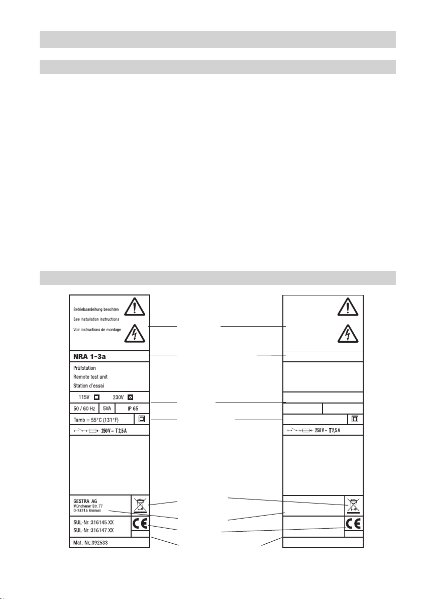
The test station NRA 1-3 is designed for the connection of up to max. 16 measuring electrodes and a
temperature sensor for measuring the plant temperature.
The test station NRA 1-3 is also available with a CAN bus interface.
Function
The following electrodes can be used for monitoring steam traps:
Measuring electrode NRG 16-19 (conductive) for detecting banking-up of condensate or steam loss
(electrode submerged or exposed) or
Measuring electrode NRG 16-27, NRG 16-28 for detecting steam loss (conductive) and
banking-up of condensate by measuring the condensate temperature by means of an integrated
temperature sensor Pt 1000.
Three LEDs indicate banking-up of condensate, steam loss and malfunction in measuring electrode
(cable disruption, short circuit) and a three-digit seven-segment display shows the number of the faulty
steam trap. If more than one steam trap are defective the numbers of the faulty traps are indicated one
after another.
If banking-up of condensate, steam loss or malfunction in measuring electrode is indicated, an output
relay for the collective alarm will also be energised.
When using the measuring electrodes NRG 16-27, NRG 16-28 you can set the switchpoint for the
message “Banking-up of condensate” as a function of the plant temperature that is detected separately
or of the temperature measured in the steam trap.
The seven-segment display indicates every 6 months the maintenance interval of the measuring
electrodes in the form of an error code.
The seven-segment display indicates also status and error messages.
For processing the measured values by a visual display unit - e. g. Spectorcontrol - the test station
NRA 1-3 is available with a CAN bus interface. The CANopen protocol is used for data exchange. The
electronic address (node ID) identifies the test station.
System components
TRG 5-53 (e.g.)
Temperature sensor with resistance thermometer Pt 100 for measuring the plant temperature.
NRG 16-19
Measuring electrode for detecting banking-up of condensate or steam loss (electrode submerged or
exposed).
NRG 16-27, NRG 16-28
Measuring electrode for detecting banking-up of condensate or steam loss (electrode submerged or
exposed) with integrated temperature sensor Pt 1000 for measuring the condensate temperature.

6
NRA 1-3 / NRA 1-3 with CAN Bus interface
Technical Data
Supply voltage
230 V, 50 / 60 Hz
115 V, 50 / 60 Hz optional
Only NRA 1-3 with CAN Bus interface
Supply voltage
24 V DC +/- 20 % via CAN Bus interface
Data exchange
CAN bus to ISO 11898, CANopen protocol
NRA 1-3 and NRA 1-3 with CAN bus interface
Fuse
external, slow-blow 200 mA
Power consumption
max. 5 VA
Inputs
16 inputs for measuring electrodes NRG 16-19, NRG 16-27, NRG 16-28
1 input for temperature sensor, e. g. TRG 5-53, measuring insert PT 100
max. length of connecting cables: 100 m
Output
1 volt free changeover contact, 4 A 24 V AC/DC, 115 V AC and 230 V AC
Inductive loads must be provided with interference suppressors (RC combinations) as specified by the
manufacture
Electrode voltage
12 V
Settings for banking-up of condensate
Difference between condensate and plant temperatures dts 1 K to 100 K, adjustable in steps of 1 K
(mode 1 and 6)
Difference between condensate temperature and switchpoint "Banking-up of condensate" dtC
1 K to 100 K, adjustable in steps of 1 K (mode 2 and 7)
Switchpoint "Banking-up of condensate" 0 °C to 255 °C,adjustable in steps of 5 K (mode 2 and 7)
Indicators and adjustors
1 three-digit seven-segment LED display, red, for indicating faulty steam traps and status and error
messages
3 LEDs for indicating banking-up of condensate, steam loss and malfunction in measuring electrode
3 pushbuttons for operating the equipment
1 ten-pole code switch for system configuration, node ID and baud rate setting
Versions
NRA 1-3a for wall mounting
NRA 1-3e for panel mounting
Housing material: ABS
Protection
NRA 1-3a: IP 65 to EN 60529
NRA 1-3e: Front: IP 65 to EN 60529, back: IP 00
Protection
NRA 1-3a: 2 (completely insulated)
Admissible ambient temperature
Max. 55 °C

7
Technical Data
Name plate/marking
Fig. 1
Housing
Housing material: ABS
Cable gland / Electrical connection
Cable gland with integral cable clamp, 8 x M 16 x 1.5,
17 five-pole screw-type terminals, conductor size 1.5 mm2
Weight
approx. 2 kg
Ambient temperature
when system is switched on: 0 ° ... 55 °C
during operation –10 °... 55 °C
Transport temperature
–20 °... +80 °C (<100 hours), defrosting time of the de-energized equipment before it can be put into
operation: 24 hours.
Storage temperature
–20 °... +70 °C, defrosting time of the de-energized equipment before it can be put into operation:24 hours.
Relative humidity
max. 95%, no moisture condensation
NRA 1-3
Max. admissible
ambient temperature
Manufacturer
Safety note
Equipment designation
Electrical specification
Protection
Disposal note
CE marking
Spare part specification
GESTRA AG
Münchener Str.77
D-28215 Bremen
Betriebsanleitung beachten
See installation instructions
Voir instructions de montage
SUL-Nr.:316147.XX
SUL-Nr.:316182.XX
NRA 1-3a CAN BUS
24V=+/- 20%
Prüfstation
Remote test unit
Station d’essai
5VA IP 65
Tamb=55°C (131°F)
250 V~ T 2,5 A
Mat.-Nr.:392721
- continued -
- continued -

8
Technical Data
Dimensions NRA 1-3
E
146.7
137
226.5
Fig. 2
Test station NRA 1-3 a
E
146.7
105
Fig. 3
Test station NRA 1-3e
Front panel cut-out 236 x 151
226.5
- continued -

9
Test station NRA 1-3a
The housing of the test station NRA 1-3a is designed for wall mounting. The four fixing holes are
accessible after opening the base part. For this purpose use a screwdriver with a broad blade to lever
the hinge out of the slot on the left side Fig. 2.
Then use suitable screws and wall plugs to fix the rear cover.
Installation
Note
Test station NRA 1-3a
After mounting the equipment you can
connect the measuring electrodes / temperature sensor
set the operating mode and the number of the measuring channels (see “Commissioning”)
in a single operation with the base part open. Then close the base part and lock the left hinge.
Test station NRA 1-3e
The housing of the test station NRA 1-3e is designed for panel mounting, panel cut-out:
236 x 151 mm. Place the equipment into the cut-out of the panel.
To unlock the hinge and swing the front panel open use a broad blade screwdriver to lever the front
panel out of the frame. Then turn the four screws for the tensioning clamps to the right until the
housing is firmly fixed in the panel cut-out, Fig. 3.
Tools
Screwdriver (5.5/100)

10
1234
12345
1234512345
1234512345
1234512345
1234512345
1234512345
1234512345
1234512345
1234512345
1234512312
1 098765
4
32
NO
Schaltwippe weiß
LN
NRA 1-3 NRA 1-3
CANopen
Electrical connection
Wiring diagram for test station NRA 1-3 and NRA 1-3 CAN
Fig. 4
NRG 16-27/-28 Intermediate
distribution frame
Condensate
Error
e. g. TRG 5-53
Disconnecting
switch
NRG 16-19
9
!
Cable tie
8
0
"
4
)
§
$
%
&
/
(
=
3
1
CH
+CL
-
CH
CL 2
3
4
5+24V
- 24V
5
6
7
Condensate
NRA 1-3 NRA 1-3 CAN
Terminal 4 (NRA 1-3)
Terminal 5 (NRA 1-3)
1
Toggle switch,
white
2

11
1Code switch for system configuration
2CAN bus interface
3Terminal for collective alarm
4Terminal for temperature sensor (system temperature)
5– =Terminals for measuring electrodes
Mode 1, 2, 4 – 7
5– =Channel 1 – 16
Electrical connection
Key
Mode 3
5Channel 1 Banking-up of condensate
6Channel 2 Banking-up of condensate
7Channel 3 Banking-up of condensate
8Channel 4 Banking-up of condensate
9Channel 5 Banking-up of condensate
0Channel 6 Banking-up of condensate
!Channel 7 Banking-up of condensate
"Channel 8 Banking-up of condensate
Mode 3
§Channel 1 Steam loss
$Channel 2 Steam loss
%Channel 3 Steam loss
&Channel 4 Steam loss
/Channel 5 Steam loss
(Channel 6 Steam loss
)Channel 7 Steam loss
=Channel 8 Steam loss
- continued -

12
Electrical connection
Connecting line of temperature sensor for detecting the plant temperature
For the connecting line use screened three-core cable, e.g. Ölflex 110 CH, manufactured by Lapp,
3 x 0.5 mm². Max. cable length between temperature sensor and test station NRA 1-3: 100 m.
Please connect screen to sensor.
Connecting line of measuring electrodes
NRG 16-19
The measuring electrode comes with a 2 m long connecting cable and can be directly connected to the
test station NRA 1-3. To extend the cable use screened two-core cable, e.g. Ölflex 110 CH, manufac-
tured by Lapp, 2 x 0.5 mm². Max. cable length between measuring electrode and test station NRA 1-3:
100 m. Please connect screen to intermediate distribution frame.
NRG 16-27, NRG 16-28
For the connecting line use screened five-core cable, e.g. Ölflex 110 CH, manufactured by Lapp,
5 x 0.5 mm². Max. cable length between measuring electrode and test station NRA 1-3: 100 m.
Please connect screen to connector.
Only for NRA 1-3 CAN: Connection of supply voltage
The equipment is supplied with 24 V DC and fused with an external slow-blow fuse 200 mA. Please use
a safety power supply unit with safe electrical isolation.
The power supply unit must be electrically isolated from dangerous contact voltages and must meet at
least the requirements on double or reinforced isolation according to one of the following standards:
DIN EN 50178, DIN EN 61010-1, DIN EN 60730-1 or DIN EN 60950.
Only for NRA 1-3 CAN: CAN bus connection, length and size of cables
Note that screened multi-cored twisted-pair control cable is required as Bus line, e. g. UNITRONIC ®BUS
CAN 2 x 2 x .. mm2or RE-2YCYV-fl 2 x 2 x .. mm2.
Cable length Number of pairs and conductor size [mm2]
125 m 2 x 2 x 0.34
250 m 2 x 2 x 0.5
335 m 2 x 2 x 0.75
500 m available on demand (depends on bus configuration)
1000 m
Wire terminal strip 2in accordance with the wiring diagram.
- continued -

13
Electrical connection
NRA 1-3a
With the base part taken off:
1. Loosen the cable glands and pull the connecting lines through the glands.
2. Remove approx. 32 cm of the end insulation of the cable and the screen.
3. Connect the wires to the terminal strips (rear of base part) according to the wiring diagram and use a
cable tie for securing the cable bundle to prevent misalignment.
4. Tighten cable glands to achieve a good seal. Use sealing plugs to seal off cable glands that are not
used.
NRA 1-3e
1. Remove approx. 30 mm of the cable end insulation.
2. Connect the wires to the terminal strips (rear of base part) according to the wiring diagram.
Electrical connection
Attention
To prevent the welding together of contacts provide an external slow-blow fuse
T 2.5 A for the output contacts.
When switching off inductive loads, voltage spikes are produced that may impair the
operation of control and measuring systems.
Connected inductive loads must be provided with suppressors such as RC combinations
as specified by the manufacturer.
Not for NRA 1-3 CAN: Install an easily accessible disconnecting switch for the test
station in the close proximity of the equipment (EN 61010-1).
Not for NRA 1-3 CAN: Mark the disconnecting switch as isolating device for the test
station.
When installing connecting lines to measuring electrodes and to the temperature
sensor make sure they are separated from power cables.
Tools
Screwdriver, size 1 and 2
Screwdriver, size 2.5, completely insulated according to DIN VDE 0680-1
Only for NRA 1-3 CAN:
Wire equipment in series. Star-type wiring is not permitted!
Link screens of bus cables such that electrical continuity is ensured and connect them
once to the central earthing point (CEP).
If two or more system components are connected in a CAN bus system, provide the
first and the last device with a terminating resistor of 120 Ω (terminal CL/CH).
The CAN bus system must not be interrupted during operation.
In the event of an interruption a malfunction alarm is raised.
- continued -

14
Factory setting
Test station NRA 1-3
The test station features the following factory set default values:
Difference between condensate temperature / plant temperature or switchpoint “Banking-up of
condensate”: 40 K.
Maintenance interval: 6 months (not adjustable)
Code switch 1Fig. 4: All switches are set to OFF
Node ID: 5 (only NRA 1-3 CAN)
Baud rate: 250 kBit/s (length of line: 125 m ) (only NRA 1-3 CAN)
Commissioning procedure
Checking electrical connection
Before commissioning the equipment please check:
Supply voltage:
Is the test station supplied with the voltage specified on the name plate?
Wiring:
Are the measuring electrodes / temperature sensor correctly wired in accordance with the wiring diagram?
Setting operating mode
Use code switch 1Fig. 4 switches S1 – S3 to set one of the following seven operating modes.
1
Mode S1 S2 S3 Plant tem-
perature Function Chan-
nels Remark
OFF OFF OFF Test
1 ON OFF OFF yes
Steam loss (conductive)
Banking-up of condensate
(temperature)
16
Compares condensate
temperature with plant tem-
perature
2 OFF ON OFF no Steam loss
Banking-up of condensate 16 Only condensate temperature
is measured
3 ON ON OFF no
Steam loss (conductive)
Banking-up of condensate
(conductive)
8No temperature measurement
4 OFF OFF ON no Steam loss 16 No temperature measurement
5 ON OFF ON no Banking-up of condensate 16 No temperature measurement
6 OFF ON ON yes Banking-up of condensate 16
Compares condensate
temperature with plant tem-
perature
7 ON ON ON no Banking-up of condensate 16 Only condensate temperature
is measured
Toggle switch, white

15
Note
In mode 3 two measuring electrodes NRG 16-19 (one for banking-up of condensate and
one for steam loss) per measuring channel are connected together so that e. g. a float trap
can be monitored. For more information see the installation instructions for NRG 16-19,
NRG 16-27, NRG 16-28.
In mode 6 and 7 the measuring electrodes NRG 16-27, NRG 16-28 receive the measure-
ments of the condensate temperature only from the integrated temperature sensor.
Commissioning procedure
Establishing number of measuring channels
Use code switch 1Fig. 4, switches S4 – S7 to set the number of measuring channels.
The switches S8 - S9 must remain in the OFF position. If necessary use switch S10 to activate the
CAN bus. See below.
1
S4 S5 S6 S7 Channels S4 S5 S6 S7 Channels
OFF OFF OFF OFF 1 OFF OFF OFF ON 9
ON OFF OFF OFF 2 ON OFF OFF ON 10
OFF ON OFF OFF 3 OFF ON OFF ON 11
ON ON OFF OFF 4 ON ON OFF ON 12
OFF OFF ON OFF 5 OFF OFF ON ON 13
ON OFF ON OFF 6 ON OFF ON ON 14
OFF ON ON OFF 7 OFF ON ON ON 15
ON ON ON OFF 8 ON ON ON ON 16
Note
If the settings of switches S1 – S7 are changed during operation, the new settings will only
be accepted by the test station after the supply voltage has been switched off and on.
Applying supply voltage
Switch on supply voltage. The seven-segment display and the LEDs will be tested, i. e. all segments
and LEDs will be illuminated / are flashing.
Toggle switch, white
Only for NRA 1-3 CAN: Activating CAN bus
To activate the CAN bus set code switch S10 1Fig. 4 to ON.
The switches S8 - S9 must remain in the OFF position.
- continued -

16
Function of keys
Key 1: Decrease value, browse
Key 3: Increase value, browse
Key 2 (E): Press briefly: Call up/Execute menu // Continue / Save settings
Key 2 (E): Press longer: Return to menu, cancel input
Key 1+3: Press longer: Reset/Delete values (e. g. alarm list + maintenance interval)
Operation, alarm and test
Specification of keys and indicators
E
Fig. 5
Key to codes on seven-segment display
LEDs 1 – 3
LED 1: Steam loss
LED 2: Banking-up of condensate
LED 3: Measuring electrodes NRG 16-27,
NRG 16-28 defective (cable disruption,
short circuit). Measuring electrodes type
NRG 16-19 are not monitored.
Code Description
The following codes can appear on the seven-segment display even if no key is being pressed:
SYS System SYS changes with plant temperature in °C
E.01 Error Incorrect configuration due to inadmissible code switch setting
E.02 Error In mode 2 and 7i the setting for banking-up of condensate is not finished
E.03 Error Maintenance interval (6 months) elapsed
C.01 – C.16 Channels 1 – 16 Indication of measuring channel
If the E key is pressed:
HIS History Alarm list detailing old alarms
InT Interval Remaining time of maintenance interval
CAL Calibration Channel calibration in mode 2
dtC (mode 2, 7) Delta TC Admissible deviation from condensate temperature in steam trap
dtS (mode 1, 6) Delta TS Admissible deviation from plant temperature
dCS (mode 1 – 4) Delay Response delay for steam loss
tSt Test LEDs and all segments are illuminated
tLO Temp Low Single channel: Minimum temperature from which monitoring takes place
GrP Group Group temperature
ALL All channels Channel selection when calibrating / setting
C.01 – C.16 Channels 1 – 16 Indication of measuring channel
don done Confirmation of input when setting parameters
clr clear Confirmation of clear command (interval, alarm)
CAN CAN Activating CAN bus
br Baudrate Changing baud rate
ID Node ID Change node ID

17
Operation, alarm and test
Mode 1, 6: After the mains voltage has been switched on and the display test has been finished the
system temperature, error messages and current alarms will be indicated.
Mode 2 to 5 and 7: After the mains voltage has been switched on and the display test has been
finished error messages and current alarms will be indicated.
For more information on the codes HIS, Int and tSt see section “Alarm list, Maintenance interval and
Test”, mode 1 to 7 (page 23).
Start
For the communication with the CAN bus each bus node requires an own address (node ID) and baud
rate (speed of data transfer) setting.
The cable length between the bus nodes dictates the baud rate setting.
Cable length Baudrate
125 m 250 kBit/s (factory setting)
250 m 125 kBit/s
335 m 100 kBit/s
500 m 50 kBit/s
1000 m 20 kBit/s
Please make the following settings:
Briefly press the E key and then key 1 until CAN is indicated on the seven-segment display. Enter the
baud rate and node ID settings.
For the node ID you can use numbers between 1 and 127.
If the baud rate and/or the node ID settings are changed the new values will only become active after
switching the power supply voltage to the test station off and on again.
Only for NRA 1-3 CAN: Setting node ID and baud rate
Start
Press key E
briefly →
←longer
HIS
Keys
(1) ↓(3) ↑
CAN
Press key E
briefly →
←longer
BR
Press key E
briefly →
←longer
Change indi-
cation
keys (1),(3)
Press key
E briefly
→
don
←
CAN
Keys
(1) ↓(3) ↑
ID
Press key E
briefly →
←longer
Change tem-
perature
keys (1),(3)
Press key
E briefly
→
don
←
ID
- continued -

18
The precondition for this operating mode is:
the use of the measuring electrodes NRG 16-27, NRG 16-28 (with integrated condensate tempera-
ture measurement at the steam trap) and
the use of a separate temperature sensor for the measurement of the system/(plant) temperature.
With the parameter dtS you can change the difference between the condensate temperature in the
steam trap and the plant temperature for all steam traps ALL or for each individual trap (C.xx). The
factory set default value is 40 K. The value can be changed in increments of 1 K and must between
between 0 and 100 K.
With the parameter tlo you can set the lower temperature limit between 0 and 100 °C in increments of
5 K. If the condensate temperature is below the temperature limit, the alarms "Banking-up of conden-
sate" and "Steam loss" will neither be indicated nor stored.
Operation, alarm and test
Setting banking-up of condensate, mode 1 to 6
SYS / °C
Press key E
briefly →
←longer
HIS
Keys
(1) ↓(3) ↑
InT
Keys
(1) ↓(3) ↑
dtS
Press key E
briefly →
←longer
ALL
Press key E
briefly →
←longer
Change tem-
perature
keys (1),(3)
Press key
E briefly
→
don
←
dtS
Keys
(1) ↓(3) ↑
Keys
(1) ↓(3) ↑
C.xx
Press key E
briefly →
←longer
Change tem-
perature
keys (1),(3)
Press key
E briefly
→
don
←
C.xx
tlo Press key E briefly →
←longer
Change temperature
keys (1),(3)
Press key
E briefly
→
don
←
tlo
- continued -

19
Operation, alarm and test
Setting banking-up of condensate, mode 2 to 7
The precondition for this operating mode is:
the use of the measuring electrodes NRG 16-27, NRG 16-28 (with integrated condensate temperature
measurement at the steam trap).
With the parameter dtC the factory set difference of 40 K (admissible condensate undercooling) between
the temperature measured at the steam trap and the switchpoint “Banking-up of condensate” can be
changed. The value can be changed in increments of 1 K and must be between 0 and 100 K.
In the parameter CAL the condensate temperature of all steam traps is polled, the difference dtC is
subtracted and the result saved.
Starting from the parameter ALL the switchpoint "Banking-up of condensate" can be adjusted in
increments of 5 K for each individual steam trap (C.xx) in order to match the settings optimally to the
operating conditions.
The parameter tlo allows you to set the lower temperature limit within a range of 0 to 100 °C in
increments of 5 K. If the condensate temperature is below the temperature limit, the alarms "Banking-up
of condensate" and "Steam loss" will neither be indicated nor stored.
y y y
Serial poll
Press key E
briefly →
←longer
HIS
Keys
(1) ↓(3) ↑
InT
Keys
(1) ↓(3) ↑
CAL
Press key E
briefly →
←longer
ALL Press key E
briefly →
Temperature
automatic
poll
auto →
don
←
CAL
Keys
(1) ↓(3) ↑
Keys
(1) ↓(3) ↑
C.xx
Press key E
briefly →
←longer
Change tem-
perature
keys (1),(3)
Press key
E briefly
→
don
←
C.xx
dtC
Press key E
briefly →
←longer
Change temperature
keys (1),(3) Press key E briefly →
don
←
dtC
Keys
(1) ↓(3) ↑
tlo Press key E briefly →
←longer
Change temperature
keys (1),(3)
Press key
E briefly
→
don
←
tlo
- continued -

20
Operation, alarm and test
Setting group temperatures in mode 1 and 6
Function
To detect banking-up of condensate the temperature of the condensate in the steam trap is compared
with the condensate temperature in the plant. The temperature sensor TRG 5-.. (Pt 100) measures the
temperature of the plant.
It is possible to divide the plant in groups.Each group requires the measurement of the group tempera-
ture and at least one detection of condensate banking-up. The plant can be split up into a maximum of
eight groups.
To measure the group temperature connect a temperature sensor Pt 1000 instead of the measuring
electrode NRG 16-27, NRG 16-28. Connect the temperature sensor to the connecting terminals 1, 2 and
3. Fig 4 5- =Connecting terminals of measuring electrodes
Examples of three groups:
Channel GrP ON / OFF Group Remark
T-Sys 1 Pt 100, plant temperature first group
C.01 OFF 1
C.02 OFF 1
C.03 ON 2 Pt 1000, plant temperature second group
C.04 OFF 2
C.05 ON 3 Pt 1000, plant temperature third group
C.06 - C.16 OFF 3
The prerequisites for operating mode 1 and 6 with measurement of group temperature are:
the use of the measuring electrodes NRG 16-27, NRG 16-28 (with integrated condensate tempera-
ture measurement at the steam trap).
the use of a separate temperature sensor for the measurement of the system/(plant) temperature.
the use of temperature sensors Pt 1000, the number of which depends on the planned groups
- continued -
Table of contents
Other GESTRA Test Equipment manuals
Popular Test Equipment manuals by other brands

ABQINDUSTRIAL
ABQINDUSTRIAL Shimpo DT-315AEB manual

Socket & See
Socket & See DLM PRO Instruction manual & specification

I-Tech
I-Tech IT8817 user manual

Fluke
Fluke Versiv Series Technical reference handbook

Instron
Instron DX Series System Concepts Manual

Van Der Stahl
Van Der Stahl PTT-100 V operating instructions