ACS Alcolock WR2 User manual

WR2 Calibration Station
Instruction Manual

Federal Communications Commission (FCC) Disclaimer
Changes or modifications not expressly approved by the party responsible for compliance could void the user’s authority to operate the
equipment.
This device complies with Part 15 of the FCC rules. Operations are subject to the following 2 conditions:
1. This device may not cause harmful interference.
2. This device must accept any interference received, including interference that may cause undesired operations.
Industry Canada
This device complies with Industry Canada licence-exempt RSS standard(s). Operation is subject to the following two conditions:
1. This device may not cause interference, and
2. This device must accept any interference, including interference that may cause undesired operation of the device.
Le présent appareil est conforme aux CNR d'Industrie Canada applicables aux appareils radio exempts de licence. L'exploitation est
autorisée aux deux conditions suivantes:
(1) L'appareil ne doit pas produire de brouillage, et
(2) L'utilisateur de l'appareil doit accepter tout brouillage radioélectrique subi, même si le brouillage est susceptible d'en compromettre
le fonctionnement.
Alcohol Countermeasure Systems Corp
60 International Boulevard
Toronto, Ontario M9W 6J2 CANADA
acs-corp.com
ALCOLOCK, ALCOSIM, ALCOHOL COUNTERMEASURE SYSTEMS, ACS, INTERTRACK and The Molly are trademarks of Alcohol
Countermeasure Systems (International) Inc. and are used under license. Alcohol Countermeasure Systems is the trading style of
Alcohol Countermeasure Systems Corp
© Alcohol Countermeasure Systems, 2012
The information disclosed in this document is the valuable property of Alcohol Countermeasure Systems and all copyright and other
proprietary rights to this document are reserved. No reproduction of this document is permitted without the prior written consent of
Alcohol Countermeasure Systems.

Contents
1.0 Introduction ........................................................................................................................................................... 1
2.0 Glossary of terminology....................................................................................................................................... 2
3.0 ACS part numbers.................................................................................................................................................2
4.0 Part descriptions................................................................................................................................................... 2
4.1 Power supply ........................................................................................................................................................................2
4.2 Auto-Cal ECU .......................................................................................................................................................................2
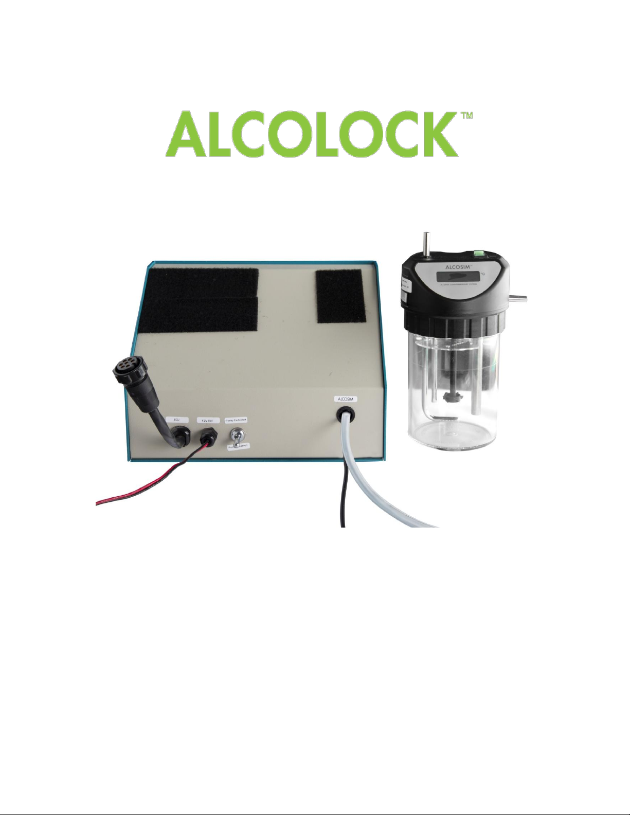
4.3 ALCOSIM breath alcohol simulator.......................................................................................................................................2
4.4 Calibration Station (CS) ........................................................................................................................................................3
4.5 Aquarium air pump................................................................................................................................................................3
4.6 ITE software..........................................................................................................................................................................3
4.7 Alcohol reference solution.....................................................................................................................................................3
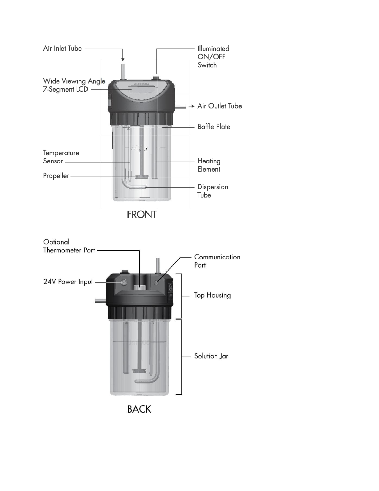
5.0 ALCOSIM breath alcohol simulator diagram......................................................................................................4
6.0 Calibration Station (CS) diagram.........................................................................................................................5
7.0 Unpacking, inspection and operating check......................................................................................................6
7.1 Inspecting the ALCOSIM simulator.......................................................................................................................................6
7.2 Inspecting the CS..................................................................................................................................................................6
7.3 Inspecting the ECU...............................................................................................................................................................6
7.4 Inspecting the aquarium air pump.........................................................................................................................................7
7.5 Inspecting the power supply..................................................................................................................................................7
8.0 Detailed operation................................................................................................................................................. 7
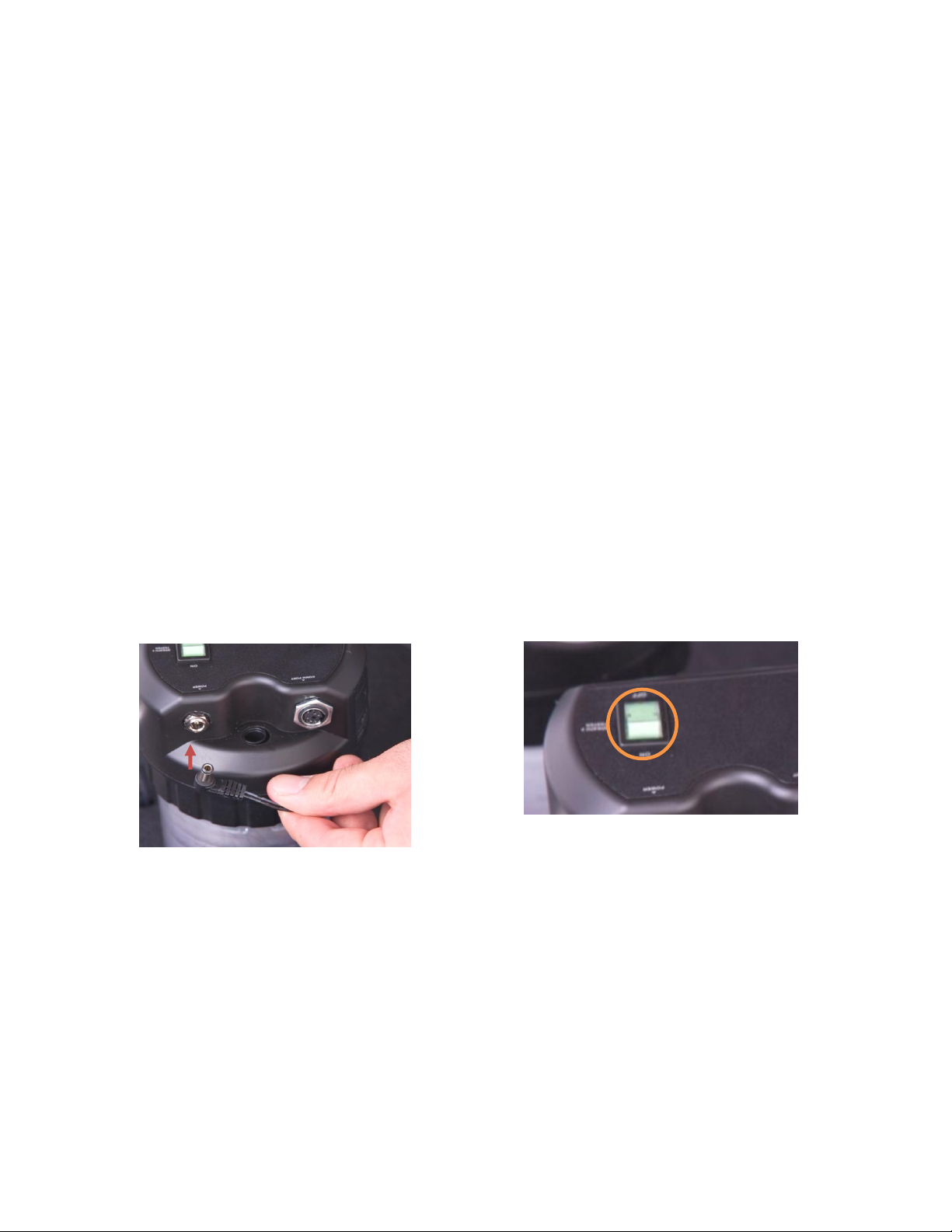
8.1 ALCOSIM breath alcohol simulator.......................................................................................................................................7
8.2 Functional test.....................................................................................................................................................................13
8.3 Verification process.............................................................................................................................................................14
8.4 Calibration process .............................................................................................................................................................14
8.5 Successful testing...............................................................................................................................................................14
9.0 Test memory of solution use .............................................................................................................................14
10.0 Automatic disabling............................................................................................................................................15
11.0 Resetting the internal counter (changing solution).........................................................................................15
12.0 Synchronization .................................................................................................................................................. 15
12.1 CS Read Procedure............................................................................................................................................................15
12.2 Result..................................................................................................................................................................................16
13.0 Reusing mouthpiece connectors ......................................................................................................................16
14.0 Troubleshooting..................................................................................................................................................17
14.1 ALCOSIM simulator –troubleshooting checklist.................................................................................................................17
14.2 ALCOSIM simulator –troubleshooting table.......................................................................................................................17
15.0 CS –Messages displayed .................................................................................................................................. 17
16.0 Problem statements............................................................................................................................................18


CALIBRATION STATION –INSTRUCTION MANUAL 1
1.0 Introduction
The ACS Calibration Station (CS) is diagnostic equipment designed to establish and maintain compliance of the ALCOLOCK
WR2 alcohol interlock Handset (HS). The following are main components required for HS calibration:
Calibration Station
WR2 Electronic Control Unit (ECU) programmed to Auto-Cal mode
WR2 Handset (HS)
ALCOSIM breath alcohol simulator
Power supply
Aquarium air pump
INTERTRACKTM enterprise software (ITE)
For successful calibration, ensure that all components of the CS assembly are connected correctly. This manual will show you
how to safely connect and operate the CS assembly, and to calibrate the ALCOLOCK WR2 device.
ATTENTION!
General
This manual is for authorized service technicians only
Do not use ALCOSIM simulator with toxic liquids, flammable liquids or in explosive atmospheres
Use the product for its intended purpose only. Failure to do so will void the warranty and may cause injury and
damage the components
Avoid contact with the ALCOSIM heating element: CAUTION –Hot Surface
Only use parts supplied by Alcohol Countermeasure Systems Corp
Do not open any enclosures. Doing so will void the warranty and may cause injury and damage the components
within. Contact your Service Provider if any hardware is not working
Ensure that the proper amount of solution is added; do not under-fill or over-fill the ALCOSIM simulator
If the ALCOSIM simulator overheats considerably beyond 34°C, turn it off and contact your Service Provider
Before use, inspect all components for visible cracks or damage. Failure to do so may cause injury or additional
damage
Do not force a cord into a port or input, as doing so will damage the components
Moisture, contamination and cleaning
The mouthpiece connector and all tubing must be completely dry before setup. Even slight condensation may
disrupt the procedure. Before beginning a calibration, make sure that all moisture has been completely removed
from the ALCOSIM simulator
The ALCOSIM jar must be completely clean and dry before you apply the alcohol reference solution. Remove the
ALCOSIM top housing before cleaning the solution jar
If liquid spills onto the CS or any other components, remove liquid with a cloth and allow to dry thoroughly. If
there is substantial moisture damage, keep all components powered off and contact your Service Provider
To clean the CS and ALCOSIM simulator: use a water dampened cloth to remove dirt or dust from the surface, and
allow it to dry thoroughly. Do not use cleaning products on the surface, as doing so may cause damage
After drying, remove all cloths or paper towels from the CS and its components
Power
Check that the ALCOSIM simulator power ratings conform to the local supply rating
Power Off the ALCOSIM simulator after use
When assembling, disassembling or preparing ALCOSIM simulator for use, ensure that it is not plugged into an
electrical outlet until you have been instructed to do so
Do not switch on the ALCOSIM simulator and CS until instructed
Do not plug in the ALCOSIM simulator or connect the CS power wires until instructed
Ensure that the power supply is disconnected until instructed
If the ALCOSIM simulator was powered on, wait 15 minutes for the components to cool off before removing the
top housing
Never open the ALCOSIM top housing when the simulator is switched on or plugged in
Do not disconnect any components while calibration is in progress
Failure to follow these instructions may result in injury or may damage the devices

Alcohol reference solution
Keep away from eyes. In case of contact, flush eyes with water. If irritation continues, contact your local poison
control centre
Do not ingest. In case of ingestion, do not induce vomiting. Contact your local poison control centre
Do not use a solution bottle with a broken seal, or a solution bottle that has expired
Keep at room temperature. Do not freeze or refrigerate
It is safe to dispose of alcohol reference solution in the drain. Refer to your local environmental regulations for
more information about safe disposal amounts
2.0 Glossary of terminology
Verification Process: The complete process used to verify the measurement accuracy of the HS.
Calibration Process: The complete process used to recalibrate the HS to allow it to complete the verification process after
adjustment.
3.0 ACS part numbers
This section list parts supplied by ACS, which are required by the Service Centre for the calibration of the ALCOLOCK WR2
device. Contact ACS to order the following parts (for contact information, refer to acs-corp.com).
Product
ACS Part #
Qty
Calibration Station
79-004401
1
ALCOSIM breath alcohol simulator assy
79-007600
1
Power supply (24V DC) with ACS label (65-000580)
07-000063
1
Alcohol reference solution 50 mg/dL (0.50 g/L)
95-000305
1 bottle
WR2 Genius+
94-000506
1
Mouthpiece connector
79-001956
1
Plastic tubes
70-000002
2
ALCOSIM communication cable add-on
79-007851
1
Power cord
07-000062 (N.A.)
07-000061 (EU)
1
Connection cable Genius –PC
79-000817
1
Elite aquarium air pump 801
40-000030
1
NOTE:ALCOSIM simulator, aquarium air pump and power supply part numbers will vary with different voltages.
4.0 Part descriptions
Read the following part summaries before beginning calibration setup.
4.1 Power supply
The power supply is an ACS provided part, but a locally purchased unit may be employed. The power supply must provide
sufficient current for successful operation of the CS, or it can lead to HS pump failures. 14amp output is the minimum.
4.2 Auto-Cal ECU
The Auto-Cal ECU is a specially modified ECU that:
Must be programmed for the jurisdiction
Cannot be used as a normal ECU
4.3 ALCOSIM breath alcohol simulator
The simulator calibration method uses a known water alcohol solution to produce an air to alcohol vapor. To simulate the
human breath, this vapour is thermostatically maintained at a constant temperature of 34°C. The result is an accurate method
of recreating a known breath alcohol concentration (BrAC).

CALIBRATION STATION –INSTRUCTION MANUAL 3
4.4 Calibration Station (CS)
The CS pump assembly is a metal box that contains an air pump and capacitor that are controlled by the ECU. The box has:
A communication plug for the ECU
An air outlet tube
A communication cable to connect to the ALCOSIM communication cable add-on (79-007851)
An isolating switch (pump switch) to allow it to conduct basic ECU tests without energizing the pump
4.5 Aquarium air pump
The aquarium air pump aids in the quick drying of the mouthpiece connector.
4.6 ITE software
The ITE software application downloads the calibration record from the ECU, for analysis.
4.7 Alcohol reference solution
The alcohol reference solution used in the CS is provided by ACS Corp in 500 mL containers. Each container is labelled with:
BAC value of the solution
Lot number of the solution
Serial (bottle) Number of each container
Date of manufacture
Expiry date
Check that the solution is the correct value –50 mg/dL (0.50 g/L) –required for calibrating, and the date is not expired.

5.0 ALCOSIM breath alcohol simulator diagram

CALIBRATION STATION –INSTRUCTION MANUAL 5
6.0 Calibration Station (CS) diagram
1
Fastening pad (ECU)
2
Fastening pad (HS)
3
Communication plug (to ECU)
4
Power wires
5
Pump switch
6
Communication cable (to ALCOSIM)
7
Air outlet tube
1
2
3
4
5
6
7

7.0 Unpacking, inspection and operating check
ATTENTION! Note the following before unpacking any components or adding water to the ALCOSIM simulator:
Ensure that the ALCOSIM simulator is unplugged and switched off until instructed
Ensure that the CS is switched to “pump disabled” and is disconnected from a power source until instructed
Ensure that the power supply is disconnected until instructed
If the ALCOSIM was powered on, wait 15 minutes for the components to cool off before removing the top housing
Never open the ALCOSIM top housing when the simulator is switched on or plugged in
Failure to follow these instructions may result in injury or may damage the devices
7.1 Inspecting the ALCOSIM simulator
1. Carefully unpack and visually inspect the unit.
2. Disassemble the solution jar from the top housing by turning the top housing counter-clockwise.
3. Carefully lift the top housing so that the internal components (e.g., the propeller) do not touch the jar.
4. Place 500 ml of tap water into the container and replace the top housing. Do not over-tighten.
5. Connect plastic tubing to the air outlet (side) and the air inlet (top).
6. Cover the air outlet tube with your thumb and blow into the air inlet tube.
It should not be possible to blow into the ALCOSIM simulator and cause bubbling of air through the solution. If air can be
freely blown into the ALCOSIM simulator, the rubber "O" ring seal is either damaged or misaligned. In this case, remove
the top housing and reposition the seal. Replace the seal if it is worn or damaged.
7. Check that the ALCOSIM simulator power rating conforms to the local supply rating.
8. Connect the power cord to the ALCOSIM power input and to the AC wall port and switch on the ALCOSIM simulator.
ALCOSIM power input:
The ALCOSIM heaters and mixing propellers automatically activate. The ALCOSIM simulator begins heating the solution
to 34°C. This takes up to 20 minutes. The ALCOSIM screen displays the solution temperature.
9. If the ALCOSIM simulator operates correctly, turn the power switch off and disconnect the power. Wait 15 minutes for the
components to cool off.
10. Remove top housing from the container. Discard water, dry out the container and tubing and wipe off components attached
to the top housing. Reassemble the top housing for storage.
7.2 Inspecting the CS
Unpack the CS and check for physical damage. Check all electrical and tube connections. Connect to power supply and check
functionality.
7.3 Inspecting the ECU
Unpack the ECU and check for physical damage. Check the electrical connector. Connect to the CS, switch power on and
check for normal ECU functionality. Disconnect and switch off the CS when finished.
ALCOSIM power switch:

CALIBRATION STATION –INSTRUCTION MANUAL 7
7.4 Inspecting the aquarium air pump
Unpack the aquarium air pump and check for physical damage. Check the electrical connector. Check that the aquarium air
pump power rating conforms to the local supply rating. Plug into an AC outlet. Check for normal air pump functionality.
7.5 Inspecting the power supply
The power supply is an ACS provided part, but a locally purchased unit could be employed. The power supply must provide
sufficient current for successful operation of the Auto-Cal station, or it can lead to Handset pump failures. 14amp output is the
minimum.
8.0 Detailed operation
8.1 ALCOSIM breath alcohol simulator
ATTENTION! Note the following before adding solution to the ALCOSIM simulator:
Ensure that the ALCOSIM simulator is unplugged and switched off until instructed
Ensure that the CS is switched to “pump disabled” and is disconnected from a power source until instructed
Ensure that the power supply is disconnected until instructed
If the ALCOSIM was powered on, wait 15 minutes for the components to cool off before removing the top housing
Never open the ALCOSIM top housing when the simulator is switched on or plugged in
Failure to follow these instructions may result in injury or may damage the devices
Preparation of the ALCOSIM simulator is critical to successful and repeat calibrations, and departure from even minor details
can create extra work. The following steps are required to ensure correct operation.
1. Disassemble the solution jar from the top housing by turning the top housing counter clockwise.
2. Clean ALCOSIM jar.
3. Add a new 50 mg/dL solution into the ALCOSIM jar, filling to (but not above) the fill line marked midway up the jar.
4. Note batch number and serial number of solution used.
NOTE: Keep the empty bottle to input to the WR2 Genius+.

5. Connect the ALCOSIM power input to a wall port. Switch ON the ALCOSIM simulator.
ALCOSIM power input:
The propeller begins turning and the solution automatically begins heating up to 34°C. This takes up to 20 minutes. The
ALCOSIM screen displays the temperature.
6. Connect a plastic tube from the ALCOSIM air outlet (side) to the mouthpiece connector, setting the connector as follows:
NOTE:
Incorrect use of the mouthpiece connector (e.g., upside down or with condensation) will lead to out of range /
inconsistent calibration action by the CS, and cause return of the HS
Change the mouthpiece connector after every 6 tests (e.g., two HS calibrations), or if droplets of liquid collect
Fit the mouthpiece connector for drying onto aquarium air pump immediately after removal to ensure adequate supply
of connectors
To ALCOSIM air outlet (side)
ALCOSIM power switch:
To Handset

CALIBRATION STATION –INSTRUCTION MANUAL 9
7. Connect the CS air outlet tube (front) to the ALCOSIM air inlet (top).
8. Connect the CS communication cable (front) to the ALCOSIM communication cable add-on (79-007851).
CS communication cable
ALCOSIM communication cable
add-on

9. Connect the ALCOSIM communication cable to the ALCOSIM communication port.
ATTENTION! Make certain that the pegs align; the plug is brittle.
10. Connect the CS red and black wires (front) to the red and black output terminals of the power supply (Back) and return
the binding posts. Plug in power supply to a wall port.
11. Connect the ECU to the left CS fastening pad.

CALIBRATION STATION –INSTRUCTION MANUAL 11
12. Connect the ECU power plug to the CS power input cable (front).
The ECU automatically powers on.
13. Connect the WR2 Genius+ to the ECU communication port.
14. Press ECU button to Zero tests.
15. The ECU displays Service.
16. On the Genius WR2+, press 3 (DIAGNOSTIC).
17. Press 6 (PREVIOUS) or 9 (NEXT) to scroll to Bottle # and press #to select.

18. Referring to your solution bottle label, use the WR2 Genius+ key pad to enter the bottle number (see example circled
below), and press 7(OK).
19. The ECU displays OK.
20. Unplug the Genius WR2+ from the ECU. The test counter on the WR2 ECU is reset 25 tests.
21. Connect the HS cable to the ECU communication port (Front).

CALIBRATION STATION –INSTRUCTION MANUAL 13
22. Connect the back of the HS to the right-side HS fastening pad, with the HS sampling port facing forward.
23. Switch the CS to “Pump Enabled”(front).
24. Press the ECU button to Zero tests.
NOTE:
The test counter on the ECU counts down from 25 tests/5 days
Change the solution after 25 tests or 5 days (whichever comes first)
Use of the solution beyond 25 tests will lead to out of range / inconsistent calibration action by the CS, and cause
return of the HS
8.2 Functional test
When an operational HS is connected, the ECU initially displays the old calibration factor, followed by WAIT. It then begins a
warming up and functional test process which checks the HS for the following:
Blow tube temperature
Pump temperature
Fuel cell temperature
Pump operation
ATTENTION! Failure of any of these tests will cause the HS to be disabled, and no further testing can be undertaken
until the unit has been returned to your distributor. If a defective HS is connected, the ECU will display the error
message and make a rejection sound, and prevent testing.
On successful completion of the functional testing, the ECU will display PRESS BUTTON TO START to subject the HS to
verification and calibration processes.
ATTENTION! A calibration cannot commence unless the ALCOSIM communication cable is connected and the alcohol
solution is at the correct operating temperature.

8.3 Verification process
The HS is tested two to three times for compliance in the calibration BAC range and, in particular, the verification BAC range.
Press button to commence testing. The ECU will display to following messages during testing:
- - - - -
While sample being injected
WAIT
While test sample being analyzed
WAIT…..
While purging
These steps will be repeated one to two times to complete the verification test.
After two tests in this range, the message VerifyOK will be displayed on the ECU and the HS can be used.
Push button to show the following:
Old calibration factor
New calibration factor
BAC 1
BAC 2
NOTE: After a successful verification process, the old and new calibration factors will be the same.
8.4 Calibration process
If the verification is not successful, but the HS is in the calibration BAC range, it is automatically calibrated by subsequent tests
and software action designed to bring the HS into the verification BAC range.
Press button to commence testing, the ECU will display to following messages during testing:
- - - - -
While sample being injected
WAIT
While test sample being analyzed
WAIT…..
While purging
These steps will be repeated two to three times to complete the calibration test.
After three tests (sometimes four) in this range, the message CAL DONE will be displayed on the ECU, and the HS can be
used.
Press button to show:
New calibration factor
Old calibration factor
BAC 1
BAC 2
BAC 3
BAC 4 (sometimes)
If calibration is unsuccessful, the HS will be disabled and must be recalibrated at your distributor.
8.5 Successful testing
On completion of successful testing, the HS can be used for a further 67 days. All calibrations completed on the CS are
retained in memory for uploading during the CS read procedure.
9.0 Test memory of solution use
The CS internal counter will maintain in memory the number of tests completed on the solution. Once the maximum number of
tests has been performed, the audible tone will sound and a display message will appear to alert the operator to change the
solution.
If the ALCOSIM simulator is not at the correct temperature, incorrectly connected, or becomes disconnected during the
calibration procedure, the ECU will display the message: Solution Not Ready, and suspend testing until the connection has
been resumed.

CALIBRATION STATION –INSTRUCTION MANUAL 15
10.0 Automatic disabling
The CS is pre-programmed to disable any HS that does not pass the calibration parameters. Once disabled, the HS cannot be
reactivated. Disabled HSs should be immediately returned to your distributor.
11.0 Resetting the internal counter (changing solution)
After 25 tests or 5 days the Change spit trap and solution. Verify 50 mg% message will display.
ATTENTION! Never use the Alcohol solution beyond 5 days or 25 tests. The HS will be incorrectly calibrated or unnecessarily
disabled.
To reset the internal counter, insert the Genius+ into the Auto-Cal ECU. Press the Diagnostic key and press the Previous key
twice until Bottle # is displayed on the screen. Verify that the solution value you are using is 50 mg/dL (0.50 g/L). Press the #
key and enter the bottle number from the new bottle of alcohol solution, then press OK. The internal counter is now reset. The
genius can now be disconnected. The bottle number will be stored into the internal memory for later audit.
Every morning prior to turning the ALCOSIM simulator on, check the number of tests available. If only several tests are left you
may wish to change the solution prior to starting calibrations, as warming the solution will take up to 20 minutes.
12.0 Synchronization
Every 60 days, the CS must be connected to ITE for a CS read transaction to download the calibration information for transfer
to the central computer during SYNC operations. If the read procedure is not completed, the CS will display Permanent
Lockout until the procedure is complete.
12.1 CS Read Procedure
The CS read procedure is a form of monitoring which is designed to upload the contents of the CS log into the database at
preset intervals.
Open ITE on PC and find the appropriate CS by first clicking on Find Client Name button at the top right hand side of the
Clients screen and choosing the appropriate CS, or by pressing the Find Connected Client button.
Start the transaction by clicking on the New Transaction button.

Click on the pull-down menu and select Cal Stat. Read. A Transaction Screen similar to
the following will be displayed:
At this stage, proceed to the CS and complete the following Genius+ procedure.
1. Connect Genius+ to ECU on CS.
2. Enter with the USER ID for the Genius+ as follows:
a) Select Diagnostic (number 3 on key pad)
b) Select Previous (number 6) - the ECU screen will show Enter ID
c) Select Odometer (Button #) on the genius to enter # plus 3 digits
d) Press OK (number 7)
3. The ECU will respond with a double-beep to confirm the number was entered correctly and the screen will show OK.
NOTE: Leave the calibration area after connecting the Genius to the PC cable.
4. Return to ITE and press the Save and Print button to start the transaction.
The Monitor screen will appear, and the progress of the read transaction can be observed.
5. The ECU will sound a triple-beep to indicate that the transaction is complete.
The CS is now ready for calibrating the HS and recording activity for the next readout.
12.2 Result
The contents of the Auto-Cal ECU are transferred to the Service Centre PC for transfer to the central computer during
synchronization. There is no printout of log details to the Service Centre, but data management staff may review the record to
discern any departures from procedures. Some international jurisdictions require these records for ongoing certification.
13.0 Reusing mouthpiece connectors
The condensation may be removed from the mouthpiece connector by connecting it to the aquarium air pump when “foggy” and
before condensation pools into fluid.
Other manuals for Alcolock WR2
1
Table of contents
Other ACS Test Equipment manuals

ACS
ACS ALERT J4X Use and care manual

ACS
ACS Alert J5 User manual

ACS
ACS DRIVESAFE User manual

ACS
ACS A1212 MASTER User manual

ACS
ACS ALCOLOCK B-2 Series Use and care manual

ACS
ACS DRIVESAFE evoc User manual

ACS
ACS SAF'IR EVOLUTION User manual

ACS
ACS WR3 User manual

ACS
ACS WR3 User manual

ACS
ACS DRIVESAFE User manual

ACS
ACS Alcocheck User manual

ACS
ACS ALERT J4X.ec User manual

ACS
ACS Alert J5 User manual

ACS
ACS Alcoscan User manual

ACS
ACS ALCOSENTRY User manual

ACS
ACS ALCOHOL INTERLOCK V3 User manual

ACS
ACS ALCOLOCK LR Programming manual

ACS
ACS ALCOCHECK User manual

ACS
ACS DRIVESAFE Use and care manual

ACS
ACS UK1401 User manual