7
EMC
Universal Counter
This instrument has been designed to meet the requirements of the EMC Directive 2004/108/EC.
Compliance was demonstrated by meeting the test limits of the following standards:
Emissions
EN61326 (2013) EMC product standard for Electrical Equipment for Measurement, Control and
Laboratory Use. Test limits used (radiated emissions only) were Class B.
Immunity
EN61326 (2013) EMC product standard for Electrical Equipment for Measurement, Control and
Laboratory Use. Test methods, limits and performance achieved are shown below (requirement
shown in brackets):
a) EN61000-4-2 (2009) Electrostatic Discharge : 8kV air, 4kV contact, Performance B (B).
b) EN61000-4-3 (2006) Electromagnetic Field:
3V/m, 80% AM at 1kHz, 80MHz – 1GHz: Performance B (A) and 1.4GHz to 2GHz:
Performance B (A); 1V/m, 2.0GHz to 2.7GHz: Performance B (A).
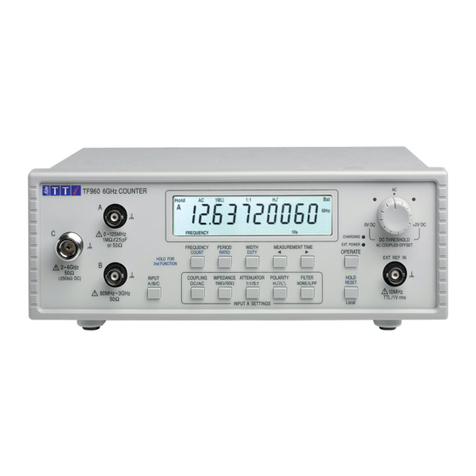
Note: The TF960 is a sensitive measuring instrument and, if subjected to a sufficiently
large RF field, may count its frequency. At lower field strengths a measurement might be
disturbed, particularly if the applied signal level is small. This is much more likely to occur
with the B input than with the A or C inputs. In all other respects, the instrument will
operate correctly (Performance A) in fields up to 3V/m.
Adaptor/Charger
This AC adaptor/charger has been designed to meet the requirements of the EMC Directive
2004/108/EC.
Compliance was demonstrated by meeting the test limits of the following standards:
Emissions
EN55022, radiated and conducted Class B.
Immunity
EN55024:1998 + A2:2003. Test methods, limits and performance achieved were:
a) EN61000-4-2 (2009) Electrostatic Discharge : 8kV air, 4kV contact, Performance B (B).
b) EN61000-4-3 (2006) Electromagnetic Field, 3V/m, 80% AM at 1kHz, Performance A (A).
c) EN61000-4-11 (2004) Voltage Interrupt: ½ cycle and 1 cycle, 0% Performance B (B);
25 cycles, 70% and 250 cycles, 0% Performance B (C).
d) EN61000-4-4 (2004) Fast Transient, 1kV peak (AC line), Performance B (B).
e) EN61000-4-5 (2006) Surge, 1kV (line to line), 2kV (line to ground), Performance B (B).
f) EN61000-4-6 (2009) Conducted RF, 3V, 80% AM at 1kHz (AC line only; DC Output
connection <3m, therefore not tested), Performance A (A).
Performance Definitions
The definitions of performance criteria are:
Performance criterion A: ‘During test normal performance within the specification limits.’
Performance criterion B: ‘During test, temporary degradation, or loss of function or
performance which is self-recovering’.
