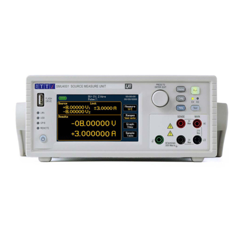
AimTTi SMU4000 Series User manual

SMU4000 SERIES
SOURCE MEASURE UNITS
INSTRUCTION MANUAL
EN

CONTENTS
CONTENTS............................................................................................................................................................ 1
Product description ..................................................................................................................................... 4
Safety............................................................................................................................................................. 5
Symbols.......................................................................................................................................................................... 5
Safety notices ................................................................................................................................................................. 6
Installation .................................................................................................................................................... 7
Mounting......................................................................................................................................................................... 7
Ventilation....................................................................................................................................................................... 7
Handle/stand .................................................................................................................................................................. 7
Electrical Requirements.................................................................................................................................................. 8
Switching On .................................................................................................................................................................. 9
Instrument overview .................................................................................................................................... 10
Front Panel................................................................................................................................................................... 10
Rear Panel.................................................................................................................................................................... 12
Introduction .................................................................................................................................................. 14
Using this Manual ......................................................................................................................................................... 14
Navigation Controls ...................................................................................................................................................... 15
Home screen ................................................................................................................................................................ 17
Getting Started ............................................................................................................................................. 19
Connections.................................................................................................................................................................. 19
High Voltage Interlock [SMU4201 only] ........................................................................................................................ 20
Basic operation............................................................................................................................................................. 21
Selecting a Range ........................................................................................................................................................ 23
Measurement selection................................................................................................................................................. 25
Saving Data.................................................................................................................................................................. 26
Sample table................................................................................................................................................................. 28
Measure Statistics ........................................................................................................................................................ 29
Graph............................................................................................................................................................................ 30
Graph Menu.................................................................................................................................................................. 31

CONTENTS
2SMU4000 Series Instruction Manual
Graph view Menu ......................................................................................................................................................... 36
Storing and Loading Setup Files................................................................................................................................... 37
Event log....................................................................................................................................................................... 40
Easy setup .................................................................................................................................................... 41
Overview....................................................................................................................................................................... 41
Manual setup ................................................................................................................................................ 42
Overview....................................................................................................................................................................... 42
Operating Mode............................................................................................................................................................ 43
Source Modes .............................................................................................................................................................. 44
Load Modes.................................................................................................................................................................. 45
Measure Modes............................................................................................................................................................ 48
Terminal selection......................................................................................................................................................... 49
Measurement count...................................................................................................................................................... 50
Source shape ............................................................................................................................................................... 51
Output off state ............................................................................................................................................................. 60
Source Control.............................................................................................................................................................. 62
Limits and Protection .................................................................................................................................................... 64
Source Level................................................................................................................................................................. 66
Timing options .............................................................................................................................................................. 67
Sequence mode ........................................................................................................................................................... 70
Digital I/O....................................................................................................................................................... 77
Overview....................................................................................................................................................................... 77
Math Functions......................................................................................................................................... 79
Applying calculations to measurements ....................................................................................................................... 79
Measure........................................................................................................................................................................ 79
Result sorting ........................................................................................................................................... 80
Tolerance...................................................................................................................................................................... 80
Application notes ..................................................................................................................................... 81

Source- Measure considerations .................................................................................................................................. 81


CONTENTS
3SMU4000 Series Instruction Manual
PowerFlex..................................................................................................................................................................... 83
System management ............................................................................................................................... 84
Maintenance.............................................................................................................................................. 88
Cleaning ....................................................................................................................................................................... 88
Remote interfaces .................................................................................................................................... 89
Overview....................................................................................................................................................................... 89
Calibration................................................................................................................................................. 90
Measurement Zero and Self Calibration ....................................................................................................................... 90
Routine Calibration ....................................................................................................................................................... 90
Factory Default settings .......................................................................................................................... 91
Specification ............................................................................................................................................. 93
Specification Conditions ............................................................................................................................................... 93
Key Specifications of SMU4000 series......................................................................................................................... 93
Output Power, Voltage and Current Capability ............................................................................................................. 96
Protection ..................................................................................................................................................................... 97
Measurement Result Buffer.......................................................................................................................................... 97
Digital Input/Output (DIO) ............................................................................................................................................. 98
Remote Control Interfaces............................................................................................................................................ 98
System Speeds ............................................................................................................................................................ 98
Environmental............................................................................................................................................................... 99
Mechanical ................................................................................................................................................................... 99

1 - Product description
4SMU4000 Series Instruction Manual
PRODUCT DESCRIPTION
The SMU4000 (Source Measure Unit) Series provides class leading performance at a new and
affordable price point for a four quadrant SMU. Combining touch screen technology with an
intuitive graphical user interface provides a clear and natural flow through the test and
measurement process.
Integrating a fast and agile, high power four quadrant voltage/ current source and advanced
precise voltage/ current meters in a compact half rack 2U casing, capable of precisely supplying
positive and negative voltages, sourcing or sinking power, while simultaneously measuring both
current and voltage for I-V characterising.
With high current and power combined with fast measurements and low glitch auto ranging
speed, it is the ideal solution for industrial development as well as educational environments,
identifying the SMU as the all-in-one solution for simplifying test applications such as battery
charging/discharging, I-V characterising, semiconductor testing and much more.

2 - Safety
Symbols
5SMU4000 Series Instruction Manual
SAFETY
Symbols
This document provides safety information and warnings which must be followed by the user to
ensure safe operation of the SMU4001 and SMU4201 and to keep the instrument in a safe
condition. The Source Measure Units described in this document are designed to be used as
general purpose test and measurement equipment. Must not be used for measurements of
Category II or higher mains circuits (as defined in IEC 60364)
User manuals, additional support and service information can be found at:
www.aimtti.com/support
The following symbols are displayed on the instrument and throughout the manual, to ensure
the safety of the user and the instrument, all information must be read before proceeding.
WARNING
Indicates a hazard that, if not avoided, could result in injury or death.
CAUTION
Indicates a hazard that could damage the product that may result in loss of important data or
invalidation of the warranty.
NOTE
Indicates a helpful tip.
EXAMPLE
Indicates an example to show further details.
Caution, possibility of electric shock
UKCA ‘UK Conformity Assessed’ marking is a
certification mark that affirms conformity
with the applicable requirements for
products sold within Great Britain.
Caution, possibility of
damage
Earth (ground) terminal
‘CE’ marking is a certification mark that
affirms the good's conformity with
European health, safety, and environmental
protection standards.
Protective Earth terminal
Standby supply. Instrument is not
disconnected from AC mains power when
switch is off.
WEEE (do not dispose in household waste)
Alternating current.

2 - Safety
Safety notices
6SMU4000 Series Instruction Manual
Safety notices
This instrument is:
·A safety Class I instrument according to IEC classification and has been
designed to meet the requirements of EN61010-1 and EN61010-2-030 (Safety
Requirements for Electrical Equipment for Measurement, Control and
Laboratory Use).
·An Installation Category II instrument intended for operation from a normal
single-phase supply.
·Supplied in a safe condition and tested in accordance with EN61010-1.
·Designed for indoor use in a Pollution Degree 2 environment in the
temperature range 5°C to 40°C, 20% - 80% RH (non-condensing) and less than
2000m altitude.
WARNING
Do not operate while condensation is present.
Do not operate outside its rated supply voltages or environmental range.
THIS INSTRUMENT MUST BE EARTHED.
Any interruption of the mains earth connector, inside or outside, will make the instrument
dangerous. Intentional interruption is prohibited.
Use of this instrument in a manner not specified by these instructions may impair the safety
protection provided
If any adjustment or repair of the opened power supply under voltage is inevitable it shall be
carried out only by a skilled person who is trained to perform such adjustments and is aware of
the hazards involved.
When connected, terminals may be live and opening the covers or removal of parts (except
those that can be accessed by hand) may expose live parts.
To avoid electric shock, or damage to the instrument, never allow water to get inside the case.
If the instrument is clearly defective, has been subject to mechanical damage, excessive
moisture, or chemical corrosion the safety protection may be impaired and it must be
withdrawn from use and returned for checking and repair.
Voltages above 60VDC are hazardous live according to EN 61010-1 and great care must be taken
when using the SMU at voltages above this level.
Capacitors inside the SMU may still be charged even if it has been disconnected from all voltage
sources, these will be safely discharged a few minutes after switching off. LEDs on the HV rail to
indicate that charge is still present, as such it’s not safe to dismantle until all LEDs have gone
out.
This instrument is protected by three internal fuses which are user serviceable (refer to the
Service Manual).
CAUTION
Do not wet when cleaning, use only a soft dry cloth to clean the screen.
Do not use sharp or pointed objects to operate the touch screen.
Take care not to restrict the inlet vents at the front, rear, sides or underneath the instrument. In
rack-mounted situations, allow adequate space around the instrument.

3 - Installation
Mounting
7SMU4000 Series Instruction Manual
INSTALLATION
Mounting
This instrument is suitable both for bench use and rack mounting.
For rack mounting the protective bezels and handle/stand should be removed such that the
instrument can be fitted beside any other standard 2U half-rack instrument in a 19” rack. A
suitable 2U 19” rack kit is available from the manufacturers or their overseas agents.
See rack mount instructions for details on how to remove the protective bezel and handle.
Ventilation
The instrument uses a fan fitted to the rear panel. Take care not to restrict the rear air exit or
the inlet vents at the front (sides and underneath). In rack-mounted situations allow adequate
space around the instrument and/or use a fan tray for forced cooling. If the air inlet vents are
restricted for any reason, the fan can be set to ‘fast’ to compensate for minimal restrictions, see
‘Air vents’ for more details.
Handle/stand
The instrument is fitted with a 4-position handle/stand. Pull out both sides of the handle at the
case pivot points to free the position locking pegs and rotate the handle from the stowed
position to the required stand or handle position. Release the sides of the handle to lock it in
the new position.

3 - Installation
Electrical Requirements
8SMU4000 Series Instruction Manual
Electrical Requirements
Mains operating voltage
CAUTION
The operating voltage is switch selectable between 115Vac or 230Vac. You must check that the
local supply meets the AC input printed on the rear panel before connecting the unit to the
supply.
Changing the mains operating voltage
Should it be necessary to change the operating voltage from 230V to 115V or vice-versa, follow
the instructions below:
WARNING
The apparatus must be disconnected from all voltage sources before it is opened for any
adjustment. Capacitors inside the SMU may still be charged even if it has been disconnected
from all voltage sources, these will be safely discharged a few minutes after switching off. LEDs
on the HV rail to indicate that charge is still present, as such it’s not safe to dismantle until all
LEDs have gone out.
Remove the case:
Mains supply voltage selection:
①Position the handle as shown.
③Slide and lift the case clear.
② Remove 2x screws from the rear panel.
A switch is located in the highlighted postiton (SW1).
Select the required value with the switch
and replace the case.
CAUTION
The set AC input voltage MUST be clearly
labeled on the rear panel.

3 - Installation
Switching On
9SMU4000 Series Instruction Manual
Mains lead
Connect the instrument to the AC supply using the mains lead provided.
Should a mains plug be required for a different mains outlet socket, a suitably rated and
approved 3 core mains lead with protective earth conductor should be used which is fitted with
the required wall plug and an IEC60320 C13 connector for the instrument end.
The minimum current rating of the lead-set for the intended AC supply is 6A or more.
WARNING
THIS INSTRUMENT MUST BE EARTHED.
Any interruption of the mains earth conductor inside or outside the instrument will make the
instrument dangerous. Intentional interruption is prohibited.
Before use, inspect provided mains lead for any signs of damage. Do not use if lead is damaged.
Before use, inspect the instrument for any signs of damage. Do not use if damaged.
Switching On
Connect the instrument to the AC supply using the mains lead provided.
Press the standby button; the button will illuminate to indicate start up. At power-up the
instrument will display a start-up message whilst initialising the application.
Loading takes a short while as the SMU will carry out self-testing and a self-calibration (at every
power cycle), after which the home screen is displayed.
To switch off, press the standby button. When powered down into standby mode the LED is
dimly lit, indicating mains power is still present.
WARNING
To fully disconnect from the AC supply, unplug the mains cord from the back of the instrument
or switch off at the AC supply outlet; make sure that the means of disconnection is readily
accessible. Disconnect from the AC supply when not in use.

4 - Instrument overview
Front Panel
10 SMU4000 Series Instruction Manual
INSTRUMENT OVERVIEW
Front Panel
① Standby button
When pressed to power up the instrument, the button will illuminate to indicate start up.
CAUTION
When powered down into standby mode, mains power is still present.
Alternative power up options are available, see ‘Power Control’for more details.
② Remote Indicator LEDs
When the instrument is being controlled remotely, the remote indicator will be illuminated,
either the LAN, USB or GPIB indicator will also be illuminated, depending on the communication
type.
③ Flash Drive
This is a USB Host port for the connection of flash drives which conform to the Mass Storage
Class specification and are formatted as FAT32.
Setups, sequences, and lists can be imported and exported via the flash drive port, see ‘Storing
and Loading Setup Files’ for more details.
Measurement data can be automatically recorded to the flash drive on completion of a test run,
see ‘Saving Data’ for more details.
Images of the display can be captured and exported using the flash drive port see ‘Icons/
indicators on the status bar’for more details
④ Rotary Knob
The rotary knob is used to navigate the user interface and scroll through values- it features a
‘press’ function to select an option, see ‘Basic operation’ for more details.
⑤ Menu Keys
-HOME- Returns to the home screen, see ‘Home screen’for more details.
-CNFG- Accesses the main menu configuration screen
①
②
③
④⑤
⑥
⑦
⑧
⑩
⑨

4 - Instrument overview
Front Panel
11 SMU4000 Series Instruction Manual
⑥ Run Key
The Run key enables the output and executes the present configuration.
⑦ Test Key
The Test key performs a quick internal self-calibration and measurement zero. See ‘Zero
Calibration’for more details.
⑧ Help Key
The context sensitive help key provides direct assistance with menus, settings, and parameters.
⑨ Terminals
The front input terminals are 4mm safety sockets on a 19mm pitch designed to accept 4mm
safety plugs with fixed or retractable shrouds.
WARNING
Only ever use either the front or rear terminals, never use both at once. Hazardous voltages
will appear on both sets of terminals.
SMU4201 Front and Rear Terminal Blocks, Main/ Force(F), Sense(S) and Guard(G) can be set
and operate at voltages up to 210Vpeak. Voltages greater than 60V are deemed hazardous
voltages.
Only use test leads conforming to IEC61010-031.
Always make connections to the instrument with the OUTPUT off and in the Open off state;
this is the only output state that completely isolates the external circuitry from the
instrument.
CAUTION
All terminals are rated to 300Vpeak with respect to earth ground. Safety will be maintained if
voltages up to 21Vpeak for SMU4001 or 210Vpeak for SMU4201, are accidentally applied
between inappropriate terminals in excess of their marked ratings. The maximum differential
between MAIN HI and SENSE HI and MAIN LO and SENSE LO should be < 2Vpeak. The SENSE
terminals are protected against accidental connection of up to 21Vpeak for SMU4001 or
210Vpeak for SMU4201 between HI & LO.
Main-Main Terminals source or sink voltage or current.
Sense-Sense terminals measure voltage. The HI Sense terminal can be used as a guard in 2 Wire
+ Guard setups. 4 Wire setups use the HI & LO Sense plus the HI & LO Main terminals.
Ground- chassis ground for ground reference purposes only. See ‘Terminal selection’ for more
details.
⑩ CV / CC LED indicator
When the output is running, the CV/ CC indicators show whether the instrument is in Constant
Voltage or Constant Current.

4 - Instrument overview
Rear Panel
12 SMU4000 Series Instruction Manual
Rear Panel
① Terminal Block
The terminal block provides rear access to the Main and Sense connections with the addition of
Guard connections.
To connect a wire, press the orange actuators of the screwless terminals, insert the connecting
wire and release the actuator to secure the connection.
Use insulated wire (solid or stranded, 0.5mm2 to 1.5mm2 (21 to 16AWG), strip length 9mm to
10mm) suitable to meet local safety standard for 300Vpeak, i.e. tri-rated 600V equipment wire
with uninsulated ferrule. Ensure there are no loose strands.
WARNING
Only ever use either the front or rear terminals, never use both at once. Hazardous voltages
will appear on both sets of terminals.
SMU4201 Front and Rear Terminal Blocks, Main/ Force(F), Sense(S) and Guard(G) can be set
and operate at voltages up to 210Vpeak Voltages greater than 60V are deemed hazardous
voltages.
Only use test leads conforming to IEC61010-031.
Always make connections to the instrument with the OUTPUT off and in the Open off state;
this is the only output state that completely isolates the external circuitry from the
instrument.
CAUTION
All terminals are rated to 300Vpeak with respect to earth ground. Safety will be maintained if
voltages up to 21Vpeak for SMU4001 or 210Vpeak for SMU4201, are accidentally applied
between inappropriate terminals in excess of their marked ratings. The maximum differential
between FORCE HI and SENSE HI and FORCE LO and SENSE LO should be < 2Vpeak. The SENSE
terminals are protected against accidental connection of up to 21Vpeak for SMU4001 or
210Vpeak for SMU4201 between HI & LO.
F +/- [Force]- Force terminals source or sink voltage or current, they are permanently wired in
parallel with the front panel Main HI and LO terminals.
①
②
③
⑦
④
⑤
⑥
⑧

4 - Instrument overview
Rear Panel
13 SMU4000 Series Instruction Manual
S +/- [Sense]- Sense terminals measure voltage and are permanently wired in parallel with the
front panel SENSE HI and LO terminals. 4 Wire setups use the HI & LO Sense plus the HI & LO
FORCE terminals.
WARNING
G [Guard] terminals
Dedicated Guard terminals only feature on the rear panel.
The Guard signal driven to the same potential as the FORCE HI. As such, if the FORCE HI is at a
hazardous voltage, the same hazardous voltage level will also be present at the Guard.
See ‘Terminal selection’ for more details.
② AC power inlet
The instrument must be connected to AC mains using the power lead provided. When the
power lead is connected this lead provides the necessary protective earth connection to an
external protective earth system. See ‘Electrical Requirements’ for more details.
③GPIB (optional)
For GPIB connection the SMU Requires a GPIB 1A user retrofittable option, available from the
manufacturers or their agents. The default GPIB address is 10. See ‘Remote interfaces’ for more
details.
④ USB
The USB device port accepts a standard USB cable. The Windows plug-and-play functions should
automatically recognise that the instrument has been connected. See ‘Remote interfaces’ for
more details.
⑤ K Lock
The Kensington slot is a standard slot that can be paired with a security cable lock.
⑥ LAN
The LAN interface is designed to meet 1.5 LXI (LAN extensions for Instrumentation) Core
2016.Remote control using the LAN interface is possible using a TCP/IP Socket protocol. See
‘Remote interfaces’for more details.
⑦ Chassis earth M4
The M4 threaded screw marked provides a connection point to safety earth ground. An M4 Ring
tab must be used, with an appropriate washer.
⑧ Digital I/O [DIO]
The DIO is an input/output port that receives, and outputs signals through digital I/O lines. See
‘Digital I/O’for more details.
+5.25Vpk Max. (diode clamped to +5V). The 5V supply is internally fused (resettable fuse) to
500mA, see the SMU4000 Series Service Manual for more information.

5 - Introduction
Using this Manual
14 SMU4000 Series Instruction Manual
INTRODUCTION
Using this Manual
This manual is a general introduction to the organisation of the instrument and is intended to be
read before using the instrument for the first time.
In this manual:
·Front panel keys and sockets are shown in capitals, e.g., HOME, CNFG;
·Text, entry fields and messages displayed on the LCD are shown in a different
font, e.g., Source, Limit, Results.
·Hyperlinks are shown in italics, e.g., ‘Using this Manual’
The descriptions in this manual relate to using the instrument via the touch screen,
alternatively; the hard keys and rotary knob can be used. See Navigation Controls for details on
how to use the rotary knob to control the instrument.
Throughout this manual, the navigation through menus will be shown at the top of a section
using the following format: MENU>Sub Menu>Option
Other Manuals are available to download for this product series including:
·Safety Documentation and Quick Start Guide [English, French, German, Italian
& Spanish]
·Programming Manual [English]
·Service Guide [English] available on request.
Available from www.aimtti.com/support.

5 - Introduction
Navigation Controls
15 SMU4000 Series Instruction Manual
Navigation Controls
Hard Keys
There are two main menus: HOME and CNFG (configuration)- These are accessed using the hard
keys on the front panel. The items within these menus can be selected using the following
options:
·Touch Screen
Direct selection and entry using touch. Simply touch the item with your finger
to select.
·Rotary Knob
Turn the knob clockwise to initiate, once the desired button has been selected,
press to engage the button. The knob can also be used to modify home screen
parameters once they have been selected.
Menu Scrolling
Some menus contain more than one page of options, when this is the case, arrows ①are
available to scroll the page up or down.
OK / Cancel
The OK and Cancel ②keys are available on all screens where changes can be made; pressing
OK will apply any changes and return the previous menu., Cancel will return to the previous
screen without making any changes.
Back Button
The Back button is available on sub menus, when pressed it will return to the previous menu.
①
②

5 - Introduction
Navigation Controls
16 SMU4000 Series Instruction Manual
Numeric Keypad / Keyboard Pop-up
Depending on where the keypad pop-up appears, the following options will be available to
select from on the keypad.
①Non-numeric Options:
Auto / Disabled etc.
②Numeric Selection
Numeric selection is 0-9, decimal point and minus sign (if negative values can be entered)
③Unit Selection
④Actions:
Bksp- Remove the previous number.
Revert-Revert the value back to the original; before the value was amended with the keypad.
Rev Pol-Available when a positive or negative value is to be accepted, toggles between plus
and minus symbol.
A full QWERTY keyboard is available for text entry.
①
②
③
④

5 - Introduction
Home screen
17 SMU4000 Series Instruction Manual
Home screen
①Status bar
•USB flash drive status (connected/disconnected) and touch to capture screen image, if
connected.
•Logged Event; a Warning, Caution or Information pop up has occurred and been logged.
Touch to see the Event Log.
•LAN Status. Touch to edit in the Interfaces menu.
•Present Mode and selected shape (if other than steady), Output status, terminal
configuration and selected OFF state. See ‘Icons’for more details. Touch to edit in the
Manual Setup menu.
•Operating voltage limit [SMU4201 only]. LV (low voltage mode) for up to ±42V working
mode, HV (high voltage mode) for up to ±210V working mode. Touch to change
between LV and HV. By default, the unit is locked into LV mode and password protected,
see ‘Password protection’ for more details.
•Date and time, touch to edit, see ‘Date and Time’ for more details.
②Source and Limits
User defined source/sink level and imposed limits, depending upon the selected mode.
Values can be modified by direct touch keypad entry, simply press on the relevant
parameter to bring up the numeric entry screen. Alternatively, the selected values can
be modified by using the rotary knob.
③Results
Results box contains the real time measurements and, if enabled, the measurement
reference and math formula applied to the readings. When in Sequence mode the
active step and operating mode will be shown.
④Buttons:
See ‘Measurement selection, ’Selecting a Range’, ‘Graph view Menu’ or ‘Sample table’
for more information.
①
②
③
④

5 - Introduction
Home screen
18 SMU4000 Series Instruction Manual
Icons/ indicators on the status bar
The following icons or indicators may appear on the status bar.
Icon
Variations
Description
①
USB Flash
Drive
Not Connected
Reading
USB Connected, Press to capture screen image
USB not supported.
③
Event log
Event logged, Press to see logged event/s
②
LAN
status
LAN
LAN detected
Press to edit Interface setup
↑↓
Data Transfer detected
LAN IP Error
LAN IP Address Error
④
Setup
Status
Press to edit the setup.
Active Mode
SV
Source Voltage
SC
Source Current
LC
Load Current
LR
Load Resistance
LP
Load Power
MV
Measure Voltage
MC
Measure Current
MR
Measure Resistance- Voltage Limited
MHR
Measure Resistance- Current Limited
SEQ
Sequence Mode
Note: If Sequence Mode is running it will show the Active Mode in the step.
Output
status
OFF
Output Off
ON
Output On
CC
Output On- Constant Current
CV
Output On- Constant Voltage
CMV
Output On- Constant Maximum Voltage
Terminal
configuration
2 Wire
Main terminals- Source and Sense
2W+Guard
Main terminals- Source and Sense. HI Sense terminal- Guard
4 Wire
Main terminals- Source and Sense. Sense Terminals- Sense
Off State
(Output Off)
0V/100µA
Source 0V/ 100uA current limit
Hi Z
Terminals are high impedance
Zero
Source 0V
Open
Terminals are open circuit
Shape
(Output On,
in place of
Off State)
Steady
Source is steady
Pulse
Source is pulsed between two levels
Sweep
Source is swept in steps between start and end levels
List
Source is defined by a custom list of levels
Pulsed sweep
Source is swept in pulsed steps between start and end levels.
⑤
Operating
Voltage
Limit *
Press to activate/deactivate the High Voltage Interlock. Note: To access the High Voltage
Interlock, the password protection may need to be removed first.
*SMU4201
only.
LV
Low Voltage Mode
HV
High Voltage Mode.
⑥Time
and Date
Press to edit Time and Date
①
④
②
③
⑤
⑥

6 - Getting Started
Connections
19 SMU4000 Series Instruction Manual
GETTING STARTED
Connections
Connections can be made to the front or rear terminals on the instrument. The front and rear
terminals are connected in parallel and must never be used simultaneously.
Front/Rear connections
Front and rear terminals are always active, there is no need to select between the two.
The terminals on the front panel are 4mm banana jack connectors, and the rear-panel contains
a terminal block. The rear terminals offer additional Guard connections for screening, see
‘Terminal selection’ for more details.
Front panel Main HI and LO terminals are permanently wired in parallel with the rear panel F +/-
[Force] terminals.
Front panel SENSE HI and LO terminals are permanently wired in parallel with the rear panel S
+/- [Sense] terminals
WARNING
Only ever use either the front or rear terminals, never use both at once. Hazardous voltages
will appear on both sets of terminals.
Hazardous voltages will appear on both sets of terminals.
Always make connections to the instrument with the OUTPUT off and in the Open off state;
this is the only output state that completely isolates the external circuitry from the
instrument.
Other manuals for SMU4000 Series
1
Table of contents
Other AimTTi Measuring Instrument manuals

AimTTi
AimTTi TF960 User manual

AimTTi
AimTTi PSA3605 User manual

AimTTi
AimTTi RM420 User manual

AimTTi
AimTTi HA1600A User manual

AimTTi
AimTTi TF960 User manual

AimTTi
AimTTi LCR400 User manual

AimTTi
AimTTi I-prober 520 User manual

AimTTi
AimTTi tf930 User manual

AimTTi
AimTTi PSA6005 Supplement

AimTTi
AimTTi BS407 User manual