9. Spares & Servicing
It is essential when ordering spares or replace-
ment parts to state the model number and the se-
rial number on the rating label adhered to the rear
of the unit.
The Air Curtain should be serviced annually. Air-
bloc offer a service facility, call 01384 489700.
Servicing shall be undertaken by a competent per-
son.
Any repair or alteration carried out to this product
without the prior authority from Ambi-Rad will invali-
date warranty.
Refer to Air Curtain Installation and Operating In-
struction manual for details.
Ensure electrical power is isolated from the
product.
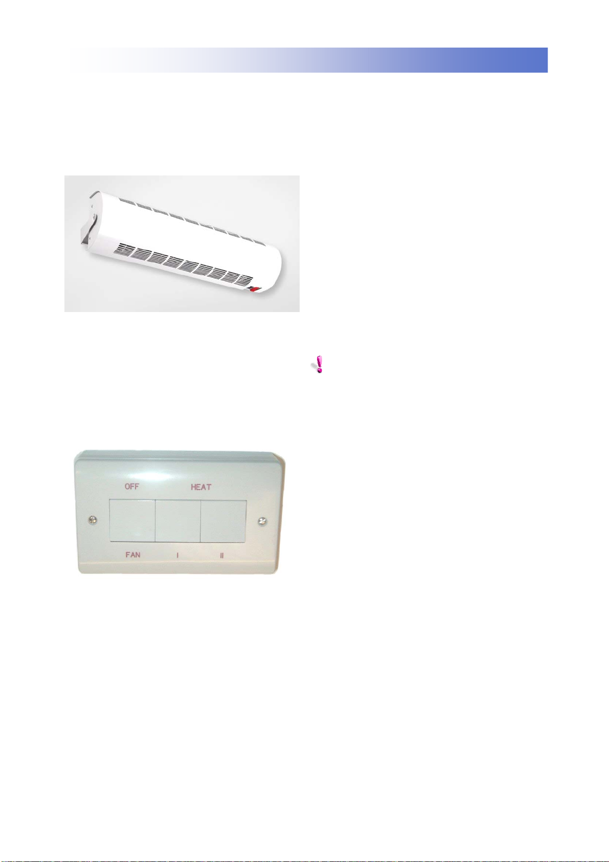
10. Replacements
ALWAYS ENSURE THAT THE MAIN EX-
TERNAL ELECTRICITY SUPPLY IS
SWITCHED OFF BEFORE COMENCING ANY
ALTERATIONS THIS HEATER.
AC600SE03
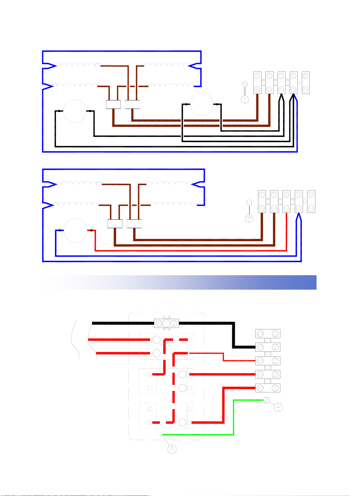
TO REPLACE THE FAN HEATER ASSEMBLY
• Isolate the unit from the electric supply.
• Remove the outer cover after disconnecting
from the swivel mounting bracket where
fitted.
• Disconnect the internal wiring from the main
terminal block and earth stud.
• Release the fixings and wiring that secure
the fan assembly to the rear panel.
• Remove the four nuts and washers fixing
the fan heater assembly to the back of the
case.
• The fan heater assembly can now be eased
forward and removed from the heater case.
• Fit replacement fan heater and re-assemble
in reverse order.
TO REPLACE A SWITCH
• Isolate the unit from the electric supply.
• Remove the top cover.
• Release the three fixings which secure the
switch bracket to the right hand side of the
main case.
• Remove the push-on connectors, noting
their position.
• Remove by compressing the plastic retain-
ing tabs, and lifting out the switch.
• Insert the new switch, refit and push on
connectors in the correct order, test and
reassemble.
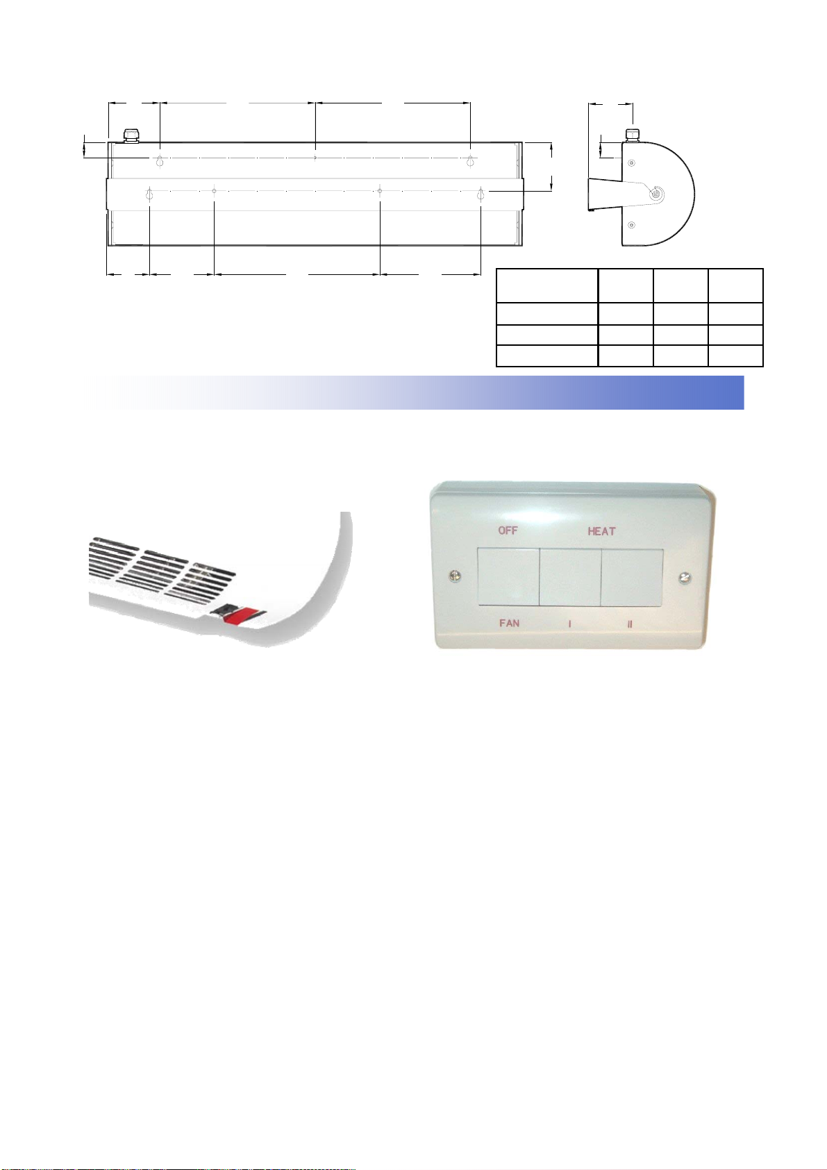
AC800SE4-5 & AC1000SE06
TO REPLACE THE FAN HEATER ASSEMBLY
• Isolate the unit from the electric supply.
• Remove the outer cover after disconnecting
from the swivel mounting bracket where
fitted.
• Disconnect the internal wiring from the main
terminal block and earth stud.
• Release the fixings and wiring that secure
the fan assembly to the rear panel.
• Fit replacement fan heater and reassemble
in reverse order.
• Test product for correct operation.
TO REPLACE A SWITCH IN THE CONTROL.
• Switch off the mains supply
• Remove the switch box cover
• Disconnect the wiring to the switch
• Remove the appropriate fixing screw(s) and
push out the switch
• Fit the replacement switch, reconnect the
wiring and replace the cover.
8. Maintenance
ALWAYS ENSURE THAT THE MAIN EXTER-
NAL ELECTRICITY SUPPLY IS SWITCHED
OFF BEFORE COMMENCING ANY MAINTE-
NANCE ON THIS HEATER.
To obtain the best results from the heater, it is
essential to avoid the accumulation of dust and
dirt within the unit on the air inlet and discharge
grilles. For this reason regular cleaning is neces-
sary, paying particular attention to the removal of
dirt build up on the rotor blades.
Cleaning of the fan is best carried out with a soft
brush.
A single drop of light oil should be applied to the
motor bearing from time to time.
Ambi-Rad Limited Fens Pool Avenue
Brierley Hill West Midlands
DY5 1QA United Kingdom
Telephone 01384 489700
Facsimile 01384 489707
Website www.airbloc.co.uk
Technical www.s-i-d.co.uk
is the registered
Trademark of Ambi-Rad Limited.
Due to continuous product
innovation, Ambi-Rad reserves the
right to change product specification
without due notice.
DOC REF GB/AIR/005/0507