Airbloc ACR100SW09 User manual

ACR RECESSED
AIR CURTAINS
AMBIENT & LPHW
STANDARD AND HIGH CAPACITY
Installation and
operating manual

Technical specification & safety details
Air curtain installation details
Rotor and motor replacement removal
General user instructions
Fitting coils
Fault finding
Spare parts
4
3
2
1
5
6
Index
7

1
General
All installations must be in accordance with the regulations in force
in the country of use.
These instructions must be given to the user on completion of
installation.
Installers and service engineers must be able to demonstrate
competence and be suitably qualified in accordance with the
regulations in force in the country of use.
To ensure continued and safe operation it is recommended that the
appliance is serviced annually.
The manufacturer, offers a maintenance service. Details available on
request.
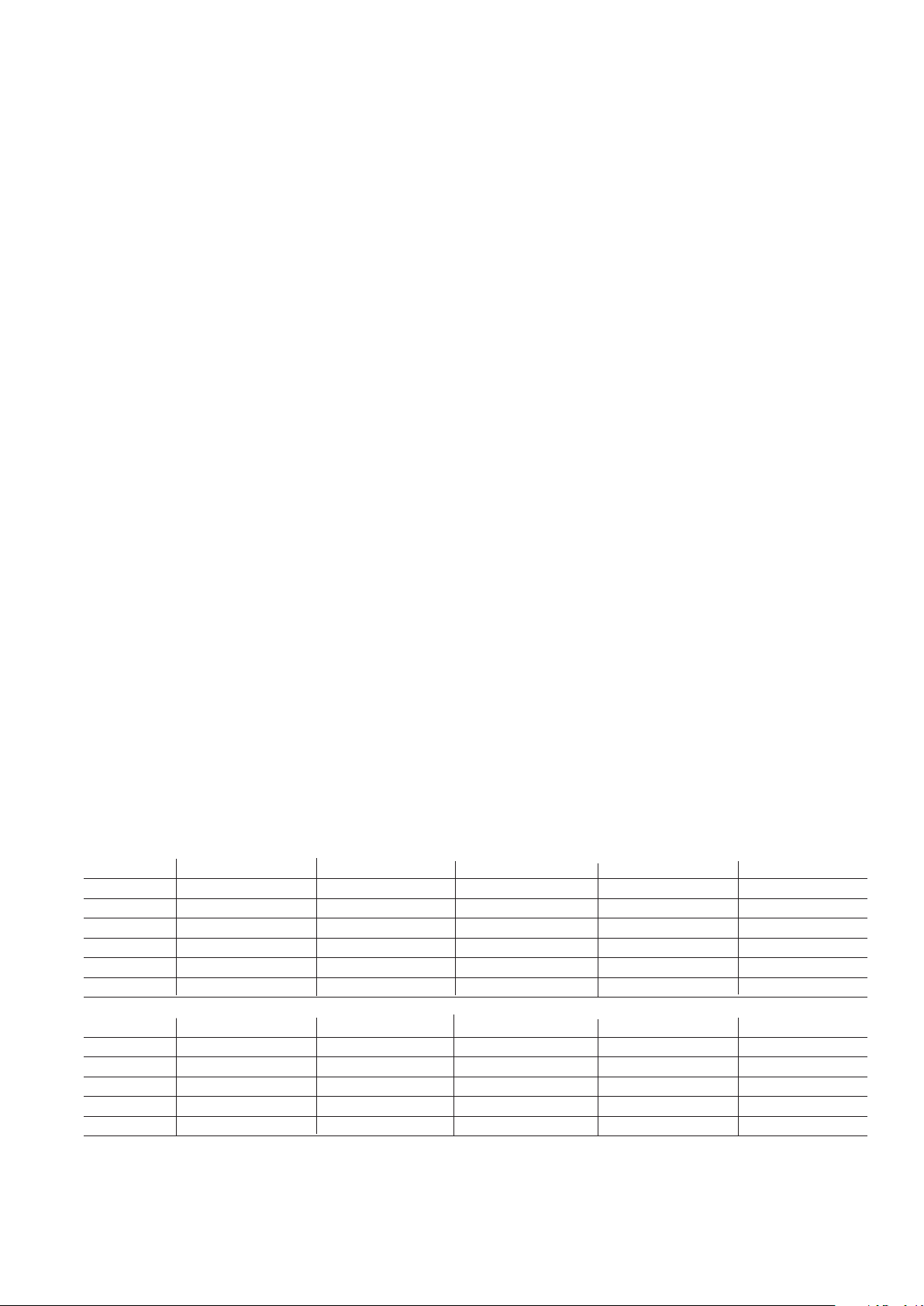
The air curtain inlet/outlet grille and case air inlet slots must not be
obstructed during use.
Fixing details
Airbloc units should be installed horizontally directly over the door
opening. It is recommended that the air curtain is installed on the
inside of the building, within the open room space against a wall or
ceiling. Care must be taken to allow complete free air movement
into the inlet grilles of the unit to ensure correct working operation
of the air curtain. The discharge opening should be as close to the
top of the door as possible and to cover the entire door width.
Electrical
The appliance must be earthed.
It is recommended that the electrical supply to the air curtain is via
an appropriate switched isolator in accordance with the regulations
in force in the country of use and must be via a fused double pole
isolator having a contact separation of >3mm in all poles.
Supply 230V 50Hz.
Time switches and thermostats can be installed at the discretion and
responsibility of the installer.
Model ACR100SA ACR150SA ACR200SA ACR120HA ACR180HA
Weight 28kg 34kg 49kg 38kg 55kg
Case size 395 x 200 x 1180mm 395 x 200 x 1480mm 395 x 200 x 1980mm 550 x 221 x 1150mm 550 x 221 x 1750mm
Motor rating 240V 50Hz 0.4A 240V 50Hz 0.4A 240V 50Hz 1.3A 240V 50Hz 2.1A 240V 50Hz 2.1A
Cut out size 405 x 1190 405 x 1490 405 x 1990 560 x1160 560 x 1760
Flange width 25mm 25mm 25mm 25mm 25mm
Note Dimension 200/221 refers to the height from the ceiling face to the outside of the case.
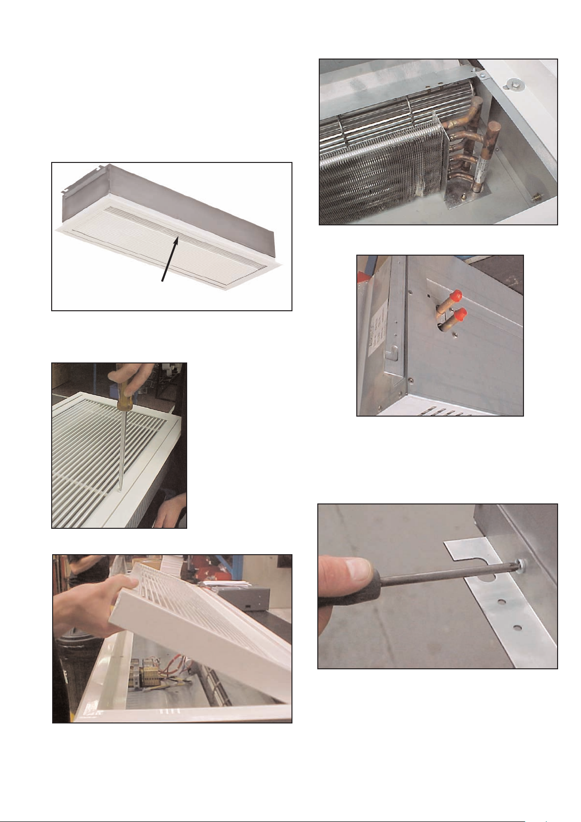
Clearance distances
It is recommended that a minimum clearance of 100mm is allowed
around the case sizes detailed below. The clearance allows for
cable entry and prevents combustible surfaces overheating. The
minimum mounting height (floor to grille) is 1.8m.
For cut out details see table below.
Health and Safety
Sole liability rests with the installer to ensure that all site safety
procedures are adhered to during installation.
Sole liability rests with the installer to ensure that protective safety
wear such as hand, eye, ear and head protection is used during
installation of the product.
Do not rest anything especially ladders against the product.
Standards
Units conform to european electrical standard BS EN 60335-2-
30:1997 and to the following european CE directives:
73/23/EEC low voltage; 89/336/EEC and 98/68/EEC electromagnetic
compatability.
1. Technical specification & safety
details
Model ACR100SW09 ACR150SW12 ACR200SW18 ACR120HW12 ACR180HW18
Weight 28kg 34kg 49kg 40kg 58kg
Case size 395 x 200 x 1180mm 395 x 200 x 1480mm 395 x 200 x 1980mm 550 x 221 x 1150mm 550 x 221 x 1750mm
Element rating 9kW 12kW 18kW 12kW 18kW
Motor rating 240V 50Hz 0.4A 240V 50Hz 0.4A 240V 50Hz 1.3A 240V 50Hz 2.1A 240V 50Hz 2.1A
Cut out size 405 x 1190 405 x 1490 405 x 1990 560 x 1160 560 x 1760
Flange width 25mm 25mm 25mm 25mm 25mm

2
Wiring Diagram ACR100SW9, ACR150SW12, ACR100SA & ACR150SA
Drawing Number 900095

Wiring Diagram ACR200SW18 & ACR200SA
3
Drawing Number 900213

Wiring Diagram ACR120HW, ACR180HW, ACR120HA & ACR180HA
4
Drawing Number 900220/R1

It is the sole responsibility of the installer to ensure that the points
of attachment to the building are sound. Consultation with the
consultant/architect or owner of the building is recommended to
ensure that a sound, mechanically stable installation is achieved.
All attachments must be capable of supporting the weight of the
product detailed in Section 1.
Step 1
Before fitting or wiring the air curtain, ensure casing faces as
above and see general installation guidance notes.
Step 2
ENSURE AIR OUTLET LOUVRES ARE NEAREST TO DOOR APPERTURE.
2 Air Curtain installation details
Access to the inside of
the air curtain grille can
be made by removing the
screws as indicated
below.
Step 3
Open the grille. The grille is hinged to prevent the inner frame
from dropping.
Step 4 Figure 1 - LPHW ONLY
The heating coils are mounted as shown in Fig 1 above. The flow
and return pipes are shown in Fig 2.
You can fit the coil for right or left hand exit by removal and
refitting of the coil fixing screws by turning the coil through 180˚.
Step 5
Step 4 Figure 2 - LPHW ONLY
Attachment of the air curtain to the ceiling structure is by means of
the two brackets attached to the side of the air curtain. The
brackets may be removed to assist in passing the air curtain
through the recess then re-attached when in-situ.
5

Step 5
Step 6
The height between the ceiling face and the face of the air
curtain case needs to be adjusted to circa 40mm to enable the
grille assembly to fit flush with the ceiling. Adjust accordingly.
After suspending the air curtain proceed to wire the product in
accordance with the wiring diagram in Section 1 of these
instructions.
Ensure that all fittings to the flow and return pipes are made
effectively and are water tight.
On completion of the above ensure that the hinge grille is
secured with the fixing screws provided.
Either 10mm or 12mm drop rods or catenary wire (available from
manufacturer) can be used to fasten the air curtain to the ceiling
support structure.
Note When using drop rods the casing mounting brackets are
slotted and the mounting plates provided must be used on
assembly.
6

Step 1
Remove fastening holding rotor support bracket
Step 2
Move rotor support bracket towards outside of case.
Step 3
Disengage rotor bearing.
Disconnect the capacitor wires.
Note Cover requires prising off capacitor.
Step 4
Step 5
Ensure on replacement of rotor that the flat on the rotor bearing
aligns with the flat on the motor shaft.
Step 6
Disconnect motor facing clips (2) using a large screwdriver and
exerting downward pressure. A sharp tap can help in releasing the
clip.
3 Rotor & motor replacement & removal
Disconnect rotor from motor shaft.
7

8
To operate the air curtain
First ensure that the electrical supply to the air curtain heater is
turned on. The panel live neon on the switch box should be
illuminated.
Ensure that the settings of any time-switch or thermostats
incorporated in the installation are in a mode to ensure that the air
curtain can operate.
By switching each rocker switch to the down position the
following combinations of control can be achieved:
•ON 1 provides low air flow and high heat.
• ON 2 provides high air flow and low heat.
• ON 1 provides low ambient air flow with no heat from coil.
•On 2 provides high ambient air flow with no heat from coil.
To switch off the air curtain
For short periods ensure that all the rocker switches are in the up
position.
For longer periods turn off the mains supply isolator.
To avoid risk of transit damage to the flow and return
connections the heating coil is provided loose inside the case
together with the air deflector plate and side supports. Unpack the
loose items and identify the two side supports as shown below and
fit to the inner side of the case using the screws
provided.
Note The side supports are handed.
Prior to installation decide if you require left hand or right hand exit
of the flow and return pipes from the product and then fix the coil
in position using the screws provided.
After fitting the coil and side supports fit the air deflector plate to
the side supports and rotor cut-off plate using the screws provided.
Side support
If the air curtain does not operate after running through the detail
provided in Section 3, then a suitably competent service engineer
should be called to identify the nature of the fault.
Note The manufacturer operates a service function from the address
provided in these instructions.
There is a cut-out incorporated in the motor winding which will
operate in the event of continued overheating.
Other faults in relation to the motor and wiring should be identified
using conventional fault finding techniques.
In the event that electrical components are replaced, please ensure
that electrical safety checks in accordance with the regulations in
force in the country of use are undertaken.
Undertake installation electrical safety checks in accordance with
the regulations in force in the country of use.
Figure 3
4 General user instructions
5 Fitting coils
6 Fault finding
Flow and Return
Pipe Exit
Coil Fitting
(Note Side supports
omitted for clarity)

Part Numbers
Photograph Description ACR100SW09 ACR150SW12 ACR200SW18 ACR120HW12 ACR180HW18
& ACR100SA & ACR150SA & ACR200SA & ACR120HA & ACR180HA
Motor 100003 100003 100012 100535 100535
Relay 900000 900000 900000 N/A N/A
Contactor N/A N/A N/A 900078 900078
Rotor LH 100001 100006 100010 100539 100540
Rotor RH 100002 100007 100011 100536 100537
7 Spare parts
Switchbox ASCP1-2 ASCP1-2 ASCP1-2 ASCP1-2 ASCP1-2
9
Coil LPHW Only
Rating 9kW 12kW 18kW
HE Part No - 103680 103607
Length - 1.2m 1.8m
SE Part No 100197 100198 100199
Length 1m 1.5m 2m

Ambi-Rad Limited - Airbloc
Fens Pool Avenue
Brierley Hill
West Midlands
DY5 1QA United Kingdom
Telephone 01384 489700
Facsimile 01384 489707
Website: www.ambirad.co.uk
For commercial/retail air curtain
enquires please contact
Due to continuous product innovation,
we reserve the right to change product
specification without due notice.
Airbloc is a registered trademark of
Ambi-Rad Limited.
Document reference number : GB/AIR/016/1006
™
This manual suits for next models
10
Table of contents
Other Airbloc Heater manuals
Popular Heater manuals by other brands

L.B. White
L.B. White Guardian 60 Assembly and installation instructions

anko
anko HD904-11 user manual

Herschel
Herschel Vulcan 6S Installation & operating instructions

Goldair
Goldair GCH255B operating instructions

RETTIG
RETTIG LST Installation, operating, maintenance & after sales manual

Optimus
Optimus H-4501 Instruction manual and owner's guide