Aircare VIS mini CAM User manual

1
VIS mini CAM
Video Inspection System
FG0175 USB receiver for a Computer & FG0176 Stand alone 5” monitor with Receiver
FG0178 includes BOTH 5” Monitor and USB receiver
Owner’s Manual (MM0173)
Topic Page
Safety Precautions 2
Storage and Cleaning 2
Parts Identification 3
Quick Start Operating
Instructions 4
Controls and Screen shots 5
Overview of Features 6
Detailed Operational Instructions
7
Specifications 11
Parts List 12
Warranty 13
Air-Care is a Division of D.P.L. Enterprises, Inc.
3868 E. Post Road, Las Vegas, NV 89120 (702) 454-5515, Fax (702) 454-5225
USB Version
for Windows
Computer
P/N FG0175
MM0173
Revised
26AUG2014
Stand Alone 5”
Monitor and
Receiver
P/N FG0176

2
Safety Precautions
1. CHARGE THE BATTERIES BEFORE FIRST USE!
oThe 12 Volt Smart charger is for the Transmitter/Battery Box.
oThe Monitor Receiver has its own charger (5 volt)
2. Read this manual carefully before using this system.
3. Avoid using the device in extremely cold, or hot or humid environment – it may damage the
device.
4. Do not drop or press hard on the device.
5. The warranty will become invalid if the device is disassembled or has any physical damages
beyond normal wear and tear.
6. Always back up your data before connecting the USB device to your system. The
manufacturer is not responsible for any data damage on your USB device for any reason.
7. Do not disconnect the unit while recording or playing. It may damage the unit or the USB
device.
IMPORTANT: Avoid kinking or pulling on the black cable as this will cause irreversible damage.
IMPORTANT: Never use the camera and/or cable as an unclogging tool, only to observe the
unclogging tool position and progress.
Storage and Cleaning
•Always return the equipment back to its protective case when not in use..
•Clean the equipment with a clean dry cloth.
•Never use solvents or abrasive solutions.
•Place the Monitor in the case with the screen facing toward the soft side, not other parts that
might break the glass.

3
Parts Identification
UNPACKING INSTRUCTIONS
Before remove items from shipping box inspect for damage. Report any damage immediately to your
carrier. Inspect all of the packing material for small parts before discarding packaging material. Report
any damage to Air-Care immediately. Any attempt at repairing damages may void the warranty.
1. 5” Monitor with built in Receiver and
DVR. Only FG0176 (Requires
optional micro SD card* to record
images and video)
2. Camera Head ASM
3. Micro SD Card (a.k.a. SDHC or TF
card) 8 GB w/ SD adapter (option)*
(P/N COM0507 and COM0509)
4. Chargers (Monitor A*, Camera B)
5. USB Receiver and DVR adapter
(included with FG0175 only)*.
6. Transmitter and Battery Case with
32 ft Video and Power extension.
7. Insertion Rod and camera Cases
(Quiver for 10 rods)
8. Camera and accessory case with
chargers, monitor*, 50 ft cable, USB
adapter*, etc.
9. Insertion Rod Ends. (10 included)
6
4B
7
2
5
1
4A
3
8
9
* Optional items
depending on
model.

4
Quick Start Operating Instructions
1. The VIS mini CAM and its accessories are in a Black Instrument Case while the Insertion Rods are in a 2” x
34” round PVC carrier (Quiver) with a screw on cap and handle.
2. The inspection can be viewed and recorded with either a Laptop PC using the USB adapter or the optional
5” Monitor with built in Receiver.
a. The 5” Monitor can be used using either the built in battery or the included AC adapter.
b. Turn it on with by holding the “M” button on top, be sure it is on “CH-1” for viewing.
c. If a Laptop will be used, IT MUST HAVE THE DRIVERS AND SOFTWARE INSTALLED BEFORE USE.
d. Insert the included disc into your CDROM/DVDROM.
Open "READ FIRST! Drivers and Software Install Manual" and follow the directions outlined in the
document.
e. Mute your sound while using the VIS mini CAM please.
3. The Camera head has a threaded coupler for the Insertion Rods.
a. Each Rod is 2.5 feet long and the VIS mini CAM comes with 10 rods.
b. Attach a rod to the camera head.
c. Be sure the rod is attached firmly to the camera head, but do not over tighten.
4. Plug in the 32 ft wire to the Camera Head and the Transmitter Box if it is not already connected.
5. Turn ON (1) the Power switch on the “Transmitter and Battery Box” and be sure the Blue light is lit on the
top of the box AND the white LED’s are lit on the Camera head.
6. Turn on the PC with USB adapter or the 5” Monitor or BOTH.
a. Be sure you see an image from the camera before inserting the camera into the ducts.
b. The USB adapter will record stills and video on the Laptop, the 5” monitor requires a micro SD card (TF)
1-32 GB (Air-Care has an optional 8 GB card for 7 hours of recording, Micro SD card P/N COM0507 and
SD Adapter COM0509). The TOP LEFT button will start the recording on the 5” Monitor when Held down
for several seconds. A short push of that button takes a still picture and saves it to the Micro SD card.
7. Using one or 2 of the 2.5 foot section of Insertion rod, slowly push the camera into the duct. You can rotate
the rods and bend it side to side to help work the camera into the duct. Always rotate Clockwise to prevent
the camera head and rods from loosening.
8. Continue adding rods as necessary until you can go no further into the duct.
9. To keep your recordings short, just VIEW the inspection while inserting the camera into the duct, then start
recording as you bring the camera out of the duct.
10. It is often helpful to write the name and location of the home and the duct on a piece of paper and
photograph it with the camera to identify the inspection video later.
11. Verify that the inspection was recorded before packing up the camera.
12. Clean off the camera head and store all of the parts in their bags.
Detailed Operating instructions for the 5” Monitor are in the booklet included with it. The USB Adapter
Instructions with its software are on the USB Adapter Install CD.
Revised
8/26/2014

5
_____________________________________________________________________
Controls on the
Optional 5” Monitor
with Receiver and
DVR.
Recording videos or stills
requires an optional micro
SD card (Micro SD Card
p/n COM0507 and SD
adapter COM0509)
Screen Shot of PC with
the USB Receiver and
DVR installed and
ready to record.
The USB adapter cannot be
used until the driver and the
software are loaded on your PC

6
Overview of Features and Controls
The Air Care mini CAM is designed specifically for video viewing and recording of Air Ducts and
similar spaces that are not accessible for direct inspections. The video adapters have many
other uses beyond video inspections. The body of this manual only covers their use in the Air
Duct video inspection environment, but you will find detailed information on all of their features
on the CD (or flash drive) for the USB adapter for Windows PC or on the booklet for the 5”
Monitor Receiver with DVR.
The VIS mini CAM is the latest development in Air-Care’s Video Inspection product line. As
video cameras, light sources, video recorders and monitor have evolved, Air-Care has
incorporated them into their Video Inspection Systems.
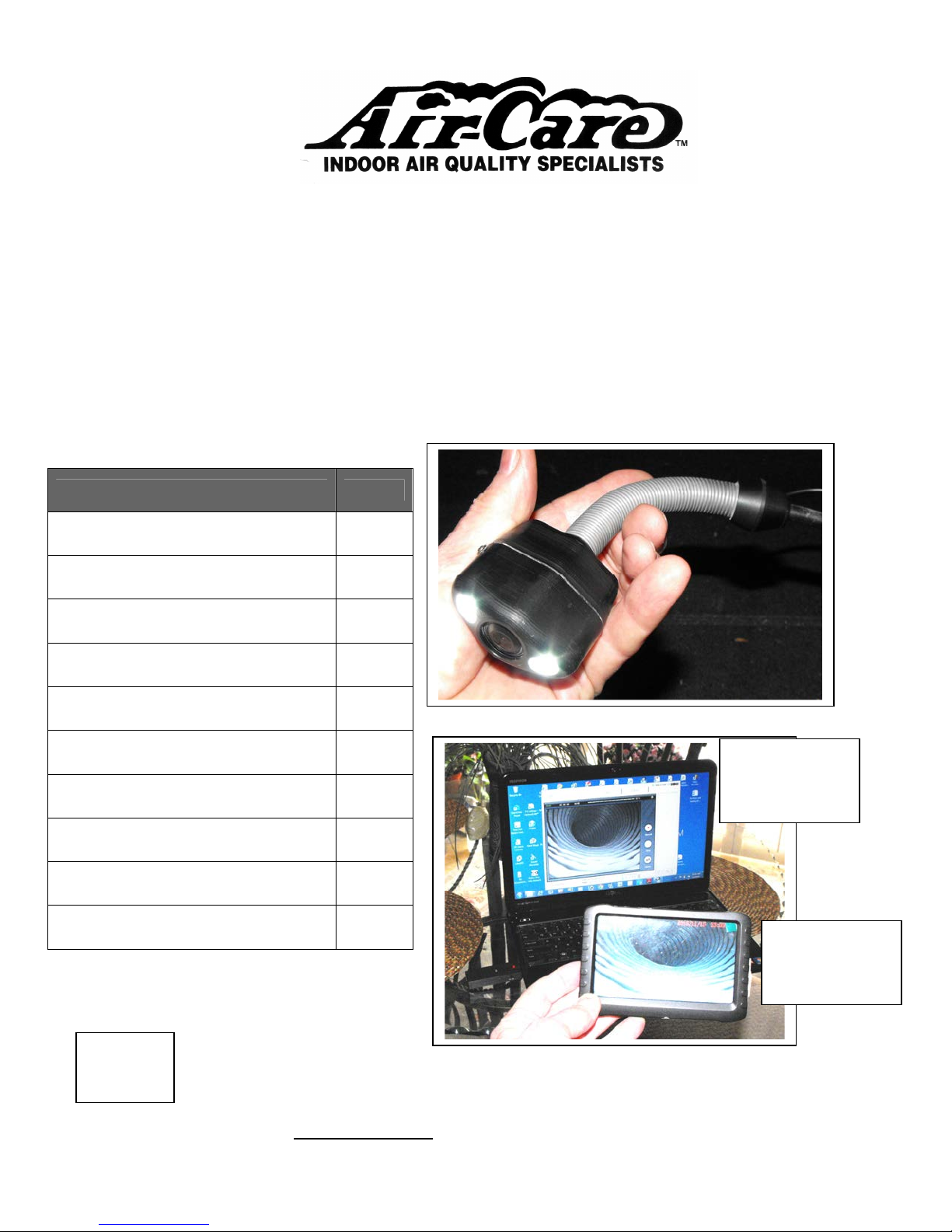
The VIS mini CAM has the best image quality and lighting of any camera on the market for this
purpose. The ultra wide angle lens and ultra-diffuse, super-bright, white LEDs render a clear,
color picture of the interior of the duct from just below the camera to the top of the same duct as
well as a clear view downstream of the camera.
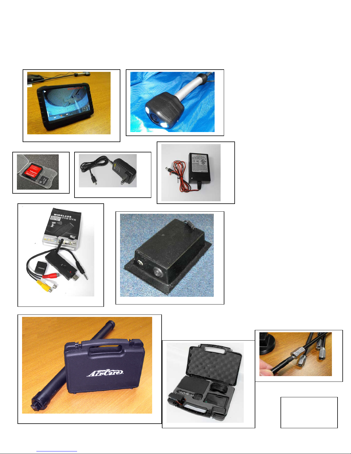
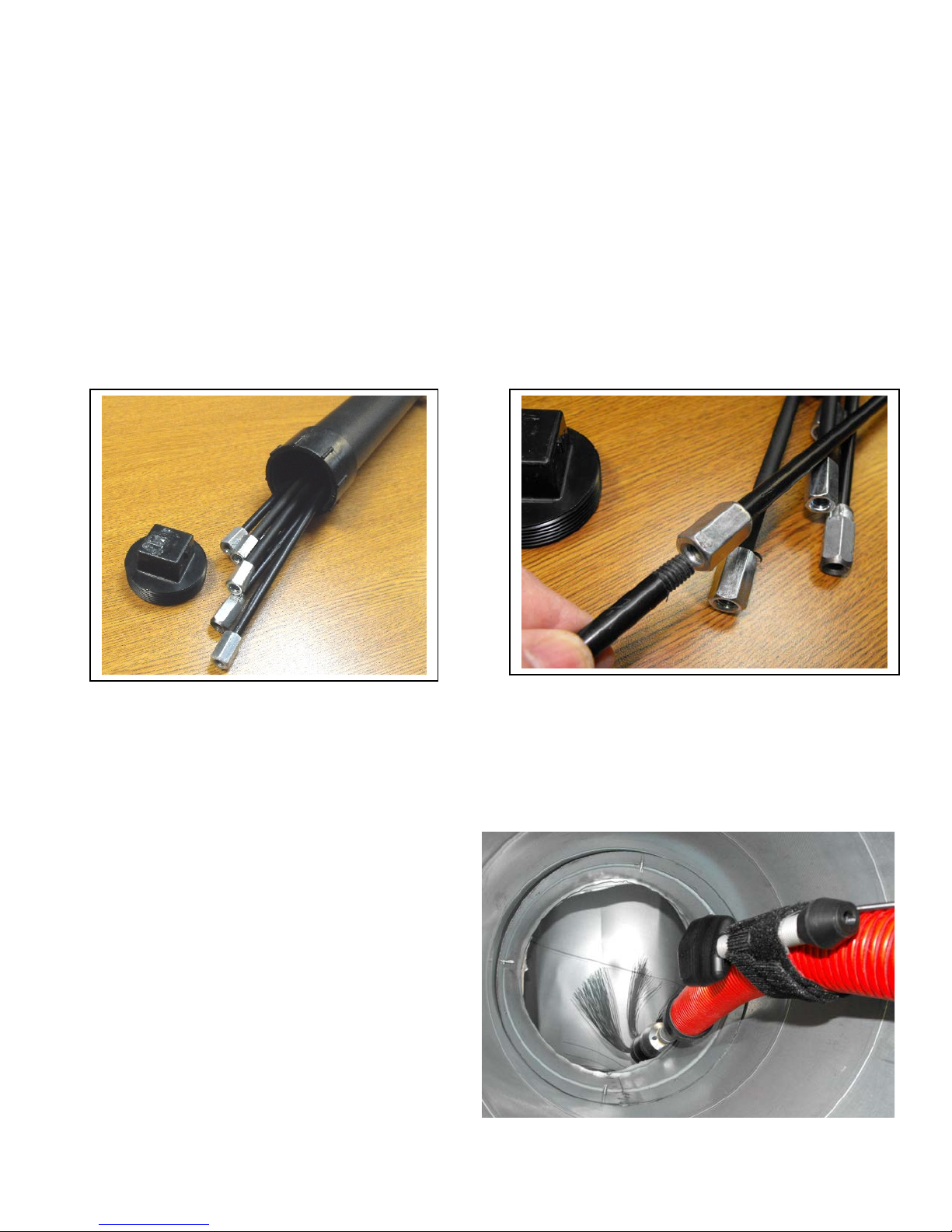
The Insertion Rods are 2.5 ft long with threaded ends and the electrical cable is 32 feet long. It
comes with 10 rods for 25 feet of inspection length, with additional rods available. The camera
head is small and streamlined to slide easily into metal, duct board and flex ducts and can be
lowered down vertical runs as well. Like the insertion rods, the electrical cable can be extended
up to 150 feet with multiple extensions.
The camera is mounted in an ultra-durable DELRIN® lightweight head that is mounted on a
flexible spring. This allows the camera to easily work its way through tight bends of the duct,
and out of pockets in a flex duct. Simply pushing it forward and twisting the rods will free it from
most obstructions.
FG0175 Camera comes with a USB Receiver that plugs into a Windows Laptop to display the
image and record it either as a video or as still pictures. With this USB adapter, there are no
wires required from the camera to the Computer. The signal is transmitted from the Camera’s
Transmitter/Battery box to the PC.
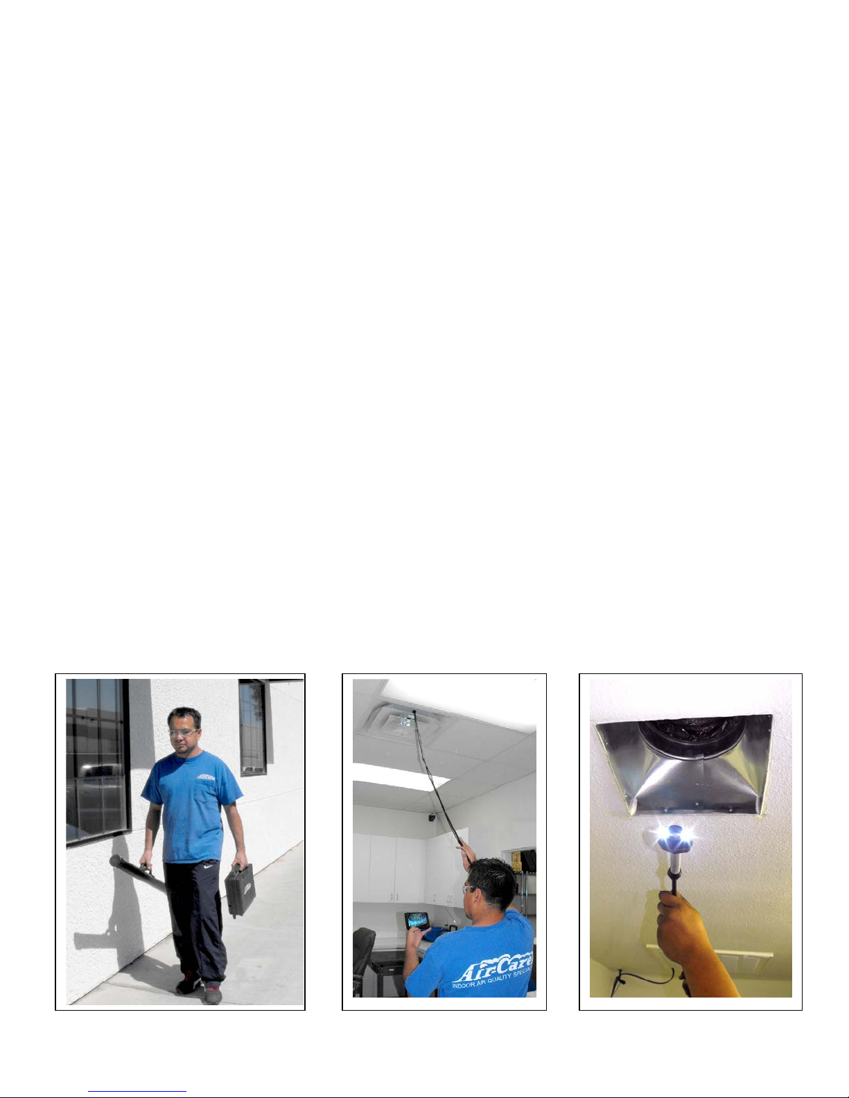
FG0176 version of the VIS mini CAM has a 5” Monitor with a receiver and built-in DVR instead
of the USB adapter. It can receive the same signal as the USB adapter and both can be used at
the same time. The Monitor stores the video or still pictures on an optional 8GB (Micro SD Card p/n
COM0507 and SD adapter COM0509), Micro SD Chip for 7 hours of recording time and playback
time(it works with 1 to 32 GB cards). The monitor has its own internal battery and can be used to
show the customer the inspection as it happens or replay it later. Using multiple 5” monitors
allows the technician to guide his cleaning tools while the customer can watch from a distance
on the second monitor.
Both systems are useful for recording images both Before and After the duct cleaning.
The batteries in the camera will last up to four hours of continuous use, and the Monitor will last
about 2 hours, but if they are discharged, both have chargers that will allow them to run on the
standard home AC power.

7
The camera, accessories, adapters, and chargers fit into a small lockable case, while the
extension rods are stored in their Quiver, a 2” diameter x 34” long rigid tube with a screw on cap.
The complete system is lightweight and easy to store and operate.
Detailed Operating Instructions for
Air Care mini CAM FG0175
•Open the instrument case and remove the Camera, Transmitter Box, roll of black wire and
either the Standard USB video adapter or the Optional 5” Monitor (or Both).
oThe Camera and Battery/Transmitter box have pigtails with a mini connector.
oThe camera can be connected directly to the Battery/Transmitter box, or the 32 foot
extension can be used. A maximum of 150 ft of cable can be installed.
oThe camera is turned on with the rocker switch on the Transmitter box.
oBe sure to turn off the Power on the Transmitter box when not in use. There is a Blue
Light on the top of the box that lights when the power is on, even if the Camera is
disconnected.
•The inspection can be viewed and recorded with either the 5” Monitor or a Laptop PC with
the USB adapter or Both.
If a Windows Laptop will be used
oInsert disc in to your CDROM/DVDROM
first! Open "READ FIRST! Drivers and
Software Install Manual" and follow the
directions outlined in the document.
Mute your sound while using the VIS mini
CAM please.
oInstall the USB adapter into a USB 2.0 slot in your Laptop.
oThe Laptop must be running Windows XP,
VISTA or Windows 7 and you
MUST INSTALL the Drivers that come with
the USB DVR adapter CD on your LAPTOP
before it will work. It is best to Install the
Drivers and test the Camera before you go
to your first job.

8
oThe 5” Monitor has it’s own battery,
but can be used with the charger plugged
into the wall if the battery has been run
down. Recharge the battery as soon as
it is convenient. To record the inspection,
you will need a Micro-SD Card (Optional) (Micro SD Card p/n COM0507 and SD adapter
COM0509). Sometimes they are called a TF card. It can use a card from 1 to 32 GB. Air
Care has an optional 8 GB card that will hold 7 hours of video
•The Camera and its LED’s are powered with a rechargeable battery in the “Transmitter Box”.
If it has been discharged, connecting the charger to a wall outlet will allow you to continue to
use it. Recharge the battery as soon as it is convenient.
•The Camera has a coupler to install a Threaded Insertion Rod into the coupler end. Each
Rod is 2.5 feet long and the Wireless VIS comes with 10 rods for a total of 25 feet. More
rods can be ordered, if needed.
oThe Rods must be screwed together firmly so that they will not come unscrewed
during the inspection. Do NOT OVER TIGHTEN them or it may be difficult to remove
them.
oThe wire should be secured to the rods to prevent tangling. The kit includes 10 “Hook
and Loop” tie straps to be used for this purpose.
oIf the Threaded end of a rod becomes damaged, it can be cut off clean and then
rethreaded with a 5/15-18 die. Call
Air Care for more detailed
information.
•If using the Cobra Power Brush, the
DuctMaster or the TruckMaster Vacuum
hose and power brush, the VIS mini
CAM can be attached to the housing or
hose.
oPosition the camera 12” to 18”
behind the brush to reduce the
vibration from the brush.
oUs the “Hook & Loop” Straps or

9
tape to attach the VIS mini CAM camera head to the brush hose or cable housing, and
secure the wire to the housing with the Hook & Loop straps provided.
oSince the vacuum hose or brush cable bends and twists, it is necessary to allow some
slack in the camera wire to prevent it from being stretched and pulling the connectors
apart or breaking the wire.
•To begin the inspection, Select the Air Duct to be inspected and remove the Grill.
•Plug in the 32 ft wire to the Camera Head and the Transmitter Box if it is not already
connected.
•Turn on the Power switch on the “Transmitter and Battery Box” and be sure the Blue light is
lit on the top of the box AND the white LED’s are lit on the Camera head.
•Turn on the Viewing Device, 5” Monitor or Laptop or both. Be sure you see an image from
the camera before inserting the camera into the ducts.
oThe 5” monitor’s “M”, on the Upper Left of the case is the main control. Hold it down
for several seconds to turn it ON or OFF, press it briefly to Mute or UnMute the sound.
Since the camera does not have sound, you may want to Mute it during an inspection.
The Button on the far left side of the top looks like a camera. Press this briefly to take
a still picture, or hold it down for several seconds to start a video -- the “REC” msg will
appear on the screen while video is recording.
oThe USB adapter should be plugged into the Laptop, then the software can be started
by clicking on the “honestech” shortcut placed on your desktop during software and
driver installation.
•You can start the recording as you insert the camera or you can just VIEW the images as the
camera is inserted and record video or Stills when you reach an interesting area you want to
document. Some operators wait until they have reached the maximum distance into the duct
before starting the recording, then they slowly pull the camera out and stop at significant
areas to record a clear image of the area.
•For a Still Picture, stop the video and briefly press the same button. After taking such a
picture, restart the video recording.
•Using 1 or 2 of the 2.5 foot sections of Insertion rod, slowly push the camera into the duct.
You can rotate the rods and bend it side to side to help work the camera into the duct.
Always rotate Clockwise to prevent the camera head and rods from loosening. It may also
help to pull back the rod a few inches and quickly thrust it forward into the duct. The camera
Head is on the end of a spring to help it work its way around obstructions and turns in the
duct.
•When you are about 4 feet into the duct, add another rod to the end of the first and push it
another 2.5 feet into the duct. You can continue this until you have reached the maximum
depth. You can now go to remove another register and inspect another section of duct, if
required.

10
•It is useful to keep the camera in one place for several seconds to clearly record interesting
parts of the ducts or dust floating in the duct or blowing past the camera. Turning the camera
over can give better views of some parts of a duct. Try to always turn the Rod
CLOCKWISE. You do NOT want to loosen the rods by turning them Counter Clockwise
unless necessary.
•If it is hard to get a good grasp of the rod to turn it, you can use a small “Vice Grip” type tool
on the metal Hex coupler nuts to turn it around.
•It is often helpful to write the name and address of the home or the customers name and date
and number the duct on a piece of paper and photograph it with the camera. That will make
reviewing several duct inspections less confusing later.
•Verify that the inspection was recorded before packing up the camera.
•Clean off the camera head and store all of the parts in their bags.
_____________________________________________________________________

11
Technical Specifications
Camera
Color CCD camera with sapphire glass lens
Viewing angle 140o
Illumination 2 High Powered white LEDs
Operating temperature 20oF – 120oF (-6oC – 50oC)
Cable
32 foot (10 m) cable sections with 4 pin Mini Connectors.
Transmitter / Receiver
Camera Transmitter: 2.4 GHz Ch. 1
USB Receiver 2.4 GHz Ch. 1-4, & 5” Mon, 2.4 GHz Ch 1-8
Monitor
5” LCD Monitor with built in Receiver
and optional micro SD memory Card
Picture Resolution – 800 x 480 pix,
2.4 GHz Receiver Ch 1-8 AV Input, NTSC/PAL
Battery, Li-OH 5 V, 3200 maH 1 Watt Speaker
Storage Medium Mini-SD, 1-32 GB (with Optional card)
USB
Compatible with Windows XP /
Vista/ 7 (64 bit) Receiver: 2.4 GHz Channels 1 through 4
USB 2.0 to computer Composite Input: AV RCA adapter, w stereo sound
Camera Power Supply (Transmitter and Battery Box) & 5” Monitor
Battery Chargers: 110-240VAC, 12VDC and
110-240 VAC, 5 VDC
NiMH Battery Rechargeable Battery, 12 Volt, 800 maH

12
VIS mini CAM (FG0175 & FG0176) Parts List
Description Part
Number Included or
Optional?
VIS mini CAM, Video Inspection System with USB adapter FG0175
VIS mini CAM, Video Inspection System with 5” Monitor Receiver and DVR FG0176
VIS mini CAM, Video Inspection System w/5” monitor AND USB adapter FG0178
USB Receiver (2.4 GHZ) with drivers and software to record video and stills
Installation CD included
COM0490 Included with
FG0175
5” Monitor with DVR and charger COM0493 Included with
FG0176
Additional Insertion Rods 2.5 ft long SAO0376 10 Included
12 Volt Charger for AC mini CAM COM0498 Included
Accessory Case for Camera and accessories, without Foam or accessories COM0491 Included
Foam with cut outs for Accessory case Top SAO0389 Included
Foam with cut outs for Accessory case Middle SAO0388 Included
Foam with cut outs for Accessory case Bottom SAO0377 Included
Camera Head with Super Bright White LED’s and Spring for tight corners SAO0382 Included
Transmitter and Battery box for Camera and LED power. SAO0387 Included
10 meter (32 ft) Power and Video cable for Camera to Power Box COM0485 1 Included
Quiver, 2” Diameter x 34” for Insertion rods Handle SAO0385 1 Included
Quick Start Sheet for Operator MM0172 Included
Complete manual with instructions for VIS min CAM MM0173 Included on
Resource CD
Micro SD card to record Video and Stills on 5” Monitor, 8 GB, Includes SD
adapter COM0509 to use in Std SD card Reader.
COM0507 Optional

13
LIMITED WARRANTY
VIS mini CAM
Air-Care warrants this product to be free from defects in materials and workmanship to the original purchaser
for a period of One (1) year from the date of purchase. Components listed below are excluded from this One
year period and are covered for periods described below:
5” Monitor With DVR 90 – Days
USB Receiver 90 – Days
Insertion Rods 90 – Days
Warranty covers both parts and labor (labor is to be performed at Air-Care’s facility located at 3868 E. Post Road; Las Vegas,
Nevada).
Warranty is extended to the original purchaser and is not transferrable.
This warranty does not extend to any damage to a product caused by or attributable to freight damage, abuse,
misuse, improper or abnormal usage. Warranty is also void if the product has been modified or altered in any
way.
The purchaser is responsible for the cost of shipping the equipment to Air-Care’s facility for evaluation. If
found to be defective and covered by the terms of this warranty, Air-Care will pay FedEx ground shipping
charges on the repaired or replaced item back to the purchaser’s location. Any additional expedited service
charges for quicker shipping shall be born by the purchaser. If the product or component is not found to be a
warranty issue, the purchaser will be responsible for return shipping charges.
Air-Care is not responsible or liable for indirect, special, or consequential damages arising out of or in
connection with the use of performance of the product; damages with respect to any economic loss, loss of
property, loss of revenues or profits, loss of use, or other incidental or consequential damages of whatsoever
nature.
The warranty extended hereunder is in lieu of any and all other warranties, and any implied warranties of any
type.
This warranty gives you specific rights. These rights and others vary from state to state.
Division of D.P.L. Enterprises Inc.
3868 East Post Road, Las Vegas, Nevada 89120, (702) 454-5515, FAX (702) 454-5225

14
Air-Care is a Division of D.P.L. Enterprises, Inc.
3868 E. Post Road, Las Vegas, NV 89120 (702) 454-5515, Fax (702) 454-5225
This manual suits for next models
3
Table of contents
Other Aircare Analytical Instrument manuals
Popular Analytical Instrument manuals by other brands

CONDTROL
CONDTROL XP3 user manual

Depstech
Depstech DS600 user manual

Teledyne Analytical Instruments
Teledyne Analytical Instruments 3000PA-EU operating instructions

USBDÜSEN
USBDÜSEN NOZZCAM operating instructions

CONDTROL
CONDTROL Sputnik 30 user manual

Precision Medical
Precision Medical Accu O2 PM5950 user manual