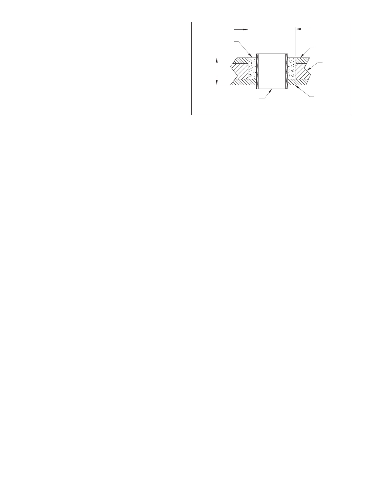
Stainless steel housing in a metal hull
—To isolate the stainless
steel housing from the metal hull, slide the isolation ring onto the
housing. Apply
additional
sealant to the surfaces of the ring that
will contact the hull, filling any cavities in and around the ring.
Installing
Caution
: Never pull, carry, or hold the multisensor by the cable as
this may sever internal connections.
1. From outside the hull, push the housing into the mounting hole
using a twisting motion to squeeze out excess marine sealant
(see Figure 3).
Align the arrow on the lip of the housing to point
forward toward the bow.
If the multisensor is not installed on the
centerline of the boat, angle the housing slightly toward the
centerline to align it with the water flow.
2. From inside the hull, slide the washer onto the housing.
Aluminum hull less than 6mm
(
1/4"
)
thick
—Use an
additional rubbery, fiberglass, or plastic washer.
Never
use
bronze since electrolytic corrosion will occur.
Never
use wood
since it will swell, possibly fracturing the plastic housing.
Warning
:
Stainless steel housing in a metal hull only
—Be
sure the washer contacts the hull. Do not tighten the hull nut
with the washer against the isolation ring as the housing will not
be firmly installed. If necessary, sand the isolation ring until the
washer rests against the hull.
3. Screw the hull nut in place
being sure
the arrow on the lip of the
housing is still positioned forward toward the bow.
Plastic housing
—
Do not
clamp tightly on the wrenching flats,
possibly causing the housing to fracture.
Plastic hull nut
—
HAND-TIGHTEN
only.
Do not
over tighten.
Metal hull nut
—Tighten with slip-joint pliers.
Cored Fiberglass Hul
l—
Do not
over tighten, crushing the hull.
Wood hull
—Allow the wood to swell before tightening the nut.
4. Remove any excess marine sealant on the outside of the hull to
ensure smooth water flow over the multisensor.
Warning: The O-rings must be intact and well lubricated to
make a watertight seal.
5. After the marine sealant cures, inspect the O-rings on the insert
(replace if necessary) and lubricate them with the silicone
lubricant supplied.
Warning
: Be sure the insert is fully inserted into the housing,
and the cap nut is screwed on completely.
6. Slide the paddlewheel insert into the housing with the
arrow on
the top pointing forward toward the bow
. Screw the cap nut
several turns until the threads are engaged. The arrow on the
top of the insert, the cable exit, and the arrow on the lip will all
be aligned. Continue to tighten the cap nut.
Be careful
not to
rotate the housing and disturb the sealant.
HAND-TIGHTEN
only.
Do not
over tighten.
Warning
: Always attach the safety wire to prevent the insert
from backing out in the unlikely event that the cap nut fails or is
screwed on incorrectly.
7. Attach the safety wire.
Plastic housing
—Attach the safety wire to one eye in the hull
nut. Keeping the wire taut throughout, lead the wire in a
counterclockwise direction and thread it through one eye in the
cap nut. Thread the wire through the eye a second time. Then
lead the wire through the eye in the insert. Twist the wire
securely to itself.
Metal housing
—Wrap one end of the safety wire tightly around
the housing and twist it together with the long end. Keeping the
wire taut throughout, lead the wire straight up and through one
eye in the cap nut. Thread the wire through the eye a second
time. Then lead the wire counterclockwise and through the eye
in the insert. Twist the wire securely to itself.
Caution
: If your multisensor came with a connector, do not
remove it to ease cable routing. If the cable must be cut and
spliced, use Airmar’s splash-proof Junction Box No. 33-035 and
follow the instructions provided. Cutting the cable or removing
the waterproof connector, except when using Airmar’s junction
box, will void the multisensor warranty.
8. Route the cable to the instrument
being careful
not to tear the
cable jacket when passing it through the bulkhead(s) and other
parts of the boat. To reduce electrical interference, separate the
multisensor cable from other electrical wiring and the engine.
Coil any excess cable and secure it in place with zip-ties to
prevent damage.
9. Refer to the instrument owner’s manual to connect the
multisensor to the instrument.
Checking for Leaks
Warning
: DO NOT leave the boat in the water unchecked for
several days.
When the boat is placed in the water,
immediately
check around
the thru-hull multisensor for leaks. Note that very small leaks may
not be readily observed.
Do not
leave the boat in the water for
more than 3 hours before checking it again. If there is a small
leak, there may be considerable bilge water accumulation after 24
hours. If a leak is observed, repeat “Bedding” and “Installing”
immediately
(see pages 2 and 3).
Installation in a Cored Fiberglass Hull
The core (wood or foam)
must
be cut and sealed carefully. The
core
must
be protected from water seepage, and the hull
must
be
reinforced to prevent it from crushing under the hull nut allowing
the housing to become loose.
Warning
: Always wear safety goggles and a dust mask.
1. Drill a 3mm or 1/8" pilot hole from inside the hull. If there is a rib,
strut, or other hull irregularity near the selected mounting location,
drill from the outside. (If the hole is drilled in the wrong location,
drill a second hole in a better location. Apply masking tape to the
outside of the hull over the incorrect hole and fill it with epoxy.)
2. Using a 51mm or 2" hole saw, cut the hole from outside the hull
through the
outer
skin only
(see Figure 4).
3. From inside the hull, use a 60mm or 2-3/8" hole saw to cut
through the
inner
skin and most of the core. The core material
can be very soft. Apply only light pressure to the hole saw after
cutting through the inner skin to avoid accidentally cutting the
outer
skin.
3
Figure 4. Preparing a cored fiberglass hull
inner skin
core
outer skin
solid or hollow cylinder
pour in
casting
epoxy
9-12 mm
(3/8-1/2")
larger than the
hole through the
hull’s outer skin
hull thickness
Copyright © 2005 Airmar Technology Corp.