Airone MOZART Guide

ISTRUZIONI PER L’USO, MANUTENZIONE E INSTALLAZIONE DELLA CAPPA
IT
INSTRUCTIONS FOR USING, MAINTAINING AND INSTALLING THE HOOD
EN
BEDIENUNGS-, WARTUNGS–UND INSTALLATIONSHANDBUCH ABZUGSHAUBE
DE
INSTRUCTIONS POUR L’UTILISATION, L’ENTRETIEN ET L’INSTALLATION DE LA HOTTE.
FR
NÁVOD K POUŽITÍ, ÚDRŽBĚA INSTALACI STOLNÍ DIGESTOŘE
CZ
HANDLEIDING VOOR HET GEBRUIK, HET ONDERHOUD EN DE INSTALLATIE VAN DE AFZUIGKAP
NL
INSTRUCCIONES PARA EL USO, MANTENIMIENTO E INSTALACION DE LA CAMPANA
ES
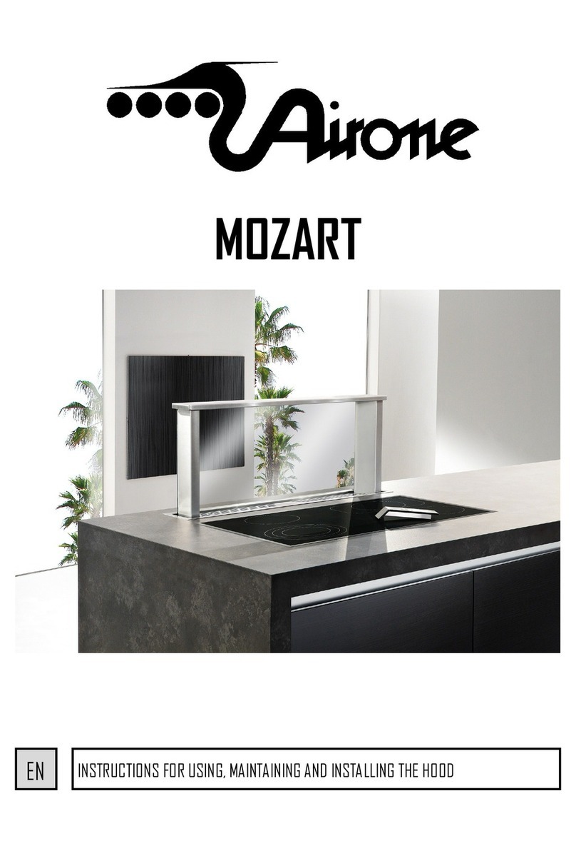
MOZART


This product complies with EU Directive 2002/96/EC.
The crossedbin symbol on the appliance indicates thatthe product, atthe endof its life, mustbedisposedofseparatelyfrom domestic waste, either bytaking itto a separate waste disposal
site for electric and electronic appliances or by returning it to your dealer when you buy another similar appliance. The user is responsible for taking the appliance to a
special waste disposal site at the end of its life. If the disused appliance is collected correctly as separate waste, it can be recycled, treated and disposed of ecological-
ly; this avoids a negative impact on both the environment and health, and contributes towards the recycling of the product’s materials. For further information regar-
ding the waste disposal services available, contact your local waste disposal agency or the shop where you bought the appliance.
Questo prodotto è conforme alla Direttiva EU 2002/96/EC.
IIsimbolo del cestino barrato riportato sull’apparecchio indica che il prodotto, alla fine della propria vita utile, dovendo essere trattato separatamente dai rifiuti domesti-
ci, deve essere conferito in un centro di raccolta differenziata per apparecchiature elettriche ed elettroniche oppure riconsegnato al rivenditore al momento dell’acqui-
sto di una nuova apparecchiatura equivalente. L’utente è responsabile del conferimento dell’apparecchio a fine vita alle appropriate strutture di raccolta. L’adeguata
raccolta differenziata per l’avvio successivo dell’apparecchio dismesso al riciclaggio, al trattamento e allo smaltimento ambientalmente compatibile contribuisce ad
evitare possibili effetti negativi sull’ambiente e sulla salute e favorisce il riciclo dei materiali di cui è composto il prodotto. Per informazioni più dettagliate inerenti i
sistemi di raccolta disponibili, rivolgersi al servizio locale di smaltimento rifiuti, o al negozio in cui è stato effettuato l’acquisto.
Dieses Produkt entspricht der EU-Richtlinie 2002/96/EC.
Die durchgestrichene Abfalltonne, die auf diesem Gerät abgebildet ist, bedeutet, dass dieses Produkt nach dem Ende seiner Betriebszeit getrennt von den Haushaltsab-
fällen zu entsorgen ist. Entweder sollte es an einer Sammelstelle für elektrische und elektronische Altgeräte abgegeben werden oder, bei Kauf eines neuen Geräts, dem
Verkäufer zurückgegeben werden. Der Verbraucher ist in jedem Falle verantwortlich für die ordnungsgemäße Entsorgung des Geräts nach Ende der Betriebszeit. Nur
bei Abgabe des Geräts an einer geeigneten Sammelstelle ist es möglich das Produkt so zu verarbeiten, zu recyceln und umweltgerecht zu entsorgen, dass einerseits
Werkstoffe und Materialien wieder verwendet werden können und andererseits negative Folgen für Umwelt und Gesundheit ausgeschlossen werden. Nähere Auskunft
bekommen Sie bei ihrem örtlichen Amt für Abfallentsorgung oder in der Verkaufsstelle dieses Geräts.
Ce produit est conforme à la Directive EU 2002/96/EC.
Le symbole de la poubelle sur l’appareil indique que ce produit , à la fin de sa propre vie utile, devra ètre traitè sèparèment des autres dèchets domestique ; il fuadra
donc l’apporter dans un centre de collecte sèlective pour les appareillages èlectriques et èlectroniques, ou bien le remettre au revendeur lors de l’achat d’ un nouvel
appareillage èquivalent. L’ utilisateur est responsable du retour de l’appareil , à la fin de sa vie , aux structures de collecte approprièes.Une collecte sèlective adèquate,
vivant à envoyer l’appareil que l’on n’ utilise plus au recyclage, au traitement et à l’elimination compatible avec l’environnement, contrìbue à èviter les effets nègatifs
possibile sur l’environnment et sur la sante, et favorise le recyclage des matèriaux dont le produit est compose. Pour obtenir des renseignements plus dètaillès sur les
systèmes de collecte disponibles, s’adresser au service local d’elimination des dèchets, ou bien au magasin où l’appareil a ètè achetè.
EN
IT
DE
FR
Dit product is conform de EU-richtlijn 2002/96/EC.
Het symbool met de doorstreepte vuilnisbak op het apparaat geeft aan dat het product op het einde van zijn levenscyclus afzonderlijk van het gewoon huishoudelijk afval
moet worden afgedankt en hiervoor naar een centrum voor gescheiden afvalophaling voor de recyclage van elektrische en elektronische apparatuur wordt gebracht of
wordt terugbezorgd aan de verkoper op het moment waarop een nieuw gelijkaardig apparaat wordt aangekocht. De gebruiker is er verantwoordelijk voor het apparaat
op het einde van de levenscyclus naar een structuur voor
afvalophaling te brengen. De correcte gescheiden afvalophaling met het oog op de daaropvolgende recyclage, verwerking en milieuvriendelijke
afdanking van het apparaat draagt bij tot het voorkomen van mogelijke negatieve invloeden op het milieu en de gezondheid en bevordert
de recyclage van de materialen waaruit het product is samengesteld. Voor meer gedetailleerde informatie over de recyclage van dit product en
de beschikbare ophaalsystemen, wendt u zich tot de lokale dienst voor afvalophaling of de winkel waar ú het product hebt gekocht.
NL
Este producto es conforme a la Directiva EU 2002/96/EC.
El simbolo de la papelera barrada que se encuentra en el aparato indica que el producto, al final de su vida ùtil , deberá eliminarse separadamente de los desechos
domèsticos y por lo tanto deberá entregarse a un centro de recogida selectiva para aparatos eléctricos y electriónicos o al vendedor cuando compre un nuevo aparato
similar. El usuario es responsable de entregar el aparato agotado a las estructuras apropìadas de recogida. La adecuada recogida selectiva para el envìo sucesivo del
aparato fuera de uso al reciclaje, al tratamiento y a la eliminacìon compatible con el ambiente, contribuye a evitar posibles efectos negativos en el ambiente y en la
salud y favorece el reciclaje de los materiales de los que está compuesto el producto. Para informaciones más detalladas inherentes a los sistemas de recogida
disponibles, dirijase al servicio local de eliminacìon de desechos, oa la tienda donde comprò el aparato.
Tento výrobek odpovídá požadavkům ES směrnice 2002/96/ES.
Symbol přeškrtnutého koše, znázorněný na zařízení upozorňuje, že tento výrobek po ukončení své životnosti nesmí být likvidován spolu s domácím odpadem a musí
se odevzdat do střediska pro separovaný sběr elektrických a elektronických zařízení nebo se musí při nákupu nového, obdobného zařízení vrátit prodejci. Uživatele je
odpovědný za odevzdání zařízení po skončení životnosti do odpovídajícího sběrného střediska. Správněprovedený separovaný sběr s následující recyklací vyřazeného
zařízení, zpracováním a ekologicky přijatelnou likvidací přispívá ke snížení nepříznivého dopadu na životní prostředí, zdraví a usnadňuje recyklaci materiálů, ze kterých
je tento výrobek vyroben. Pro podrobnější informace o přístupných možnostech likvidace zařízení se obraťte na místní služby likvidace odpadu nebo na prodejce, u
něhožjste zařízení koupili.
ES
CZ
IT -1
ISTRUZIONI PER L’USO, MANUTENZIONE E INSTALLAZIONE DELLA CAPPA DA PIANO.
Attenzione: La cappa da piano deve essere installata unicamente da personale abilitato. Si declina ogni responsabilità
in merito ad installazioni eseguite da persone prive di abilitazione.
Prima di procedere con l'installazione della cappa, leggere attentamente ed integralmente queste istruzioni. Il
presente libretto deve essere conservato per tutta la vita della cappa da piano
AVVERTENZE
Attenzione: Con la cappa da piano chiusa, non posizionare pentole ed altri contenitori con manici a ridosso
della parte superiore per evitare eventuali capovolgimenti in fase di apertura. La cappa da piano è dotata
di un sistema di sicurezza a microinterruttori che bloccano il movimento della cappa nel caso il coperchio
venga sollevato. Se in fase di chiusura della cappa, si interpone qualche oggetto tra il coperchio ed il piano,
il coperchio alzandosi determinerà il blocco del movimento. Per riattivare il movimento sarà sufficiente
riposizionare il coperchio ed attivare il comando desiderato.
L’apparecchio può essere utilizzato da bambini di età non inferiore a 8 anni e da persone con ridotte
capacità fisiche, sensoriali o mentali, o prive di esperienza o della necessaria conoscenza, purché sotto
sorveglianza oppure dopo che le stesse abbiano ricevuto istruzioni relative all’uso sicuro dell’apparecchio
e alla comprensione dei pericoli ad esso inerenti. I bambini non devono giocare con l’apparecchio. La
pulizia e la manutenzione destinata ad essere effettuata dall’utilizzatore non deve essere effettuata da
bambini senza sorveglianza.
Prima di procedere alla pulizia o alla manutenzione (periodica o straordinaria) togliere sempre
l'alimentazione elettrica alla cappa da piano staccando la spina o agendo sull'interruttore generale della
rete d’alimentazione portandolo in posizione 0 (OFF).
Non collegare la cappa da piano a condotti utilizzati per apparecchi a combustione come bruciatori, caldaie
o caminetti.
La cappa da piano deve essere utilizzata esclusivamente con l’unità di alimentazione fornita insieme ad
essa: CENTRALINA DOWN DRAFT.
La cappa da piano deve essere utilizzata esclusivamente con l’unità aspirante fornita ed indicata dal
costruttore con potenza massima di 640W.
Verificare che la tensione della rete corrisponda a quanto previsto sull'etichetta argentata posta sulla
scatola elettrica. Accertarsi che l'impianto elettrico sia realizzato con lo scarico a terra e che lo stesso
sia efficiente. Non utilizzare per la cottura materiali che possono sviluppare fiamme alte o comunque
anomale. L'olio usato due volte e grassi sono particolarmente pericolosi e potrebbero infiammarsi.
E' vietato preparare alimenti flambè.
Attenzione: le parti accessibili possono diventare calde quando la cappa da piano è utilizzata con
apparecchi di cottura.
Si consiglia di accendere la cappa alcuni minuti prima dell’utilizzo e di spegnerla 10 minuti dopo l’utilizzo.
Terminata l’installazione, da parte di un tecnico specializzato, tutti i componenti elettrici, cavi, connettori,
motori, scatola di comando e tutti i collegamenti correlati di messa a terra, devono risultare non
accessibili all’utilizzatore. L’accesso ad essi deve essere possibile esclusivamente all’installatore tramite
la rimozione di pannelli fissati con viti.

IT -2
Rispettare le norme vigenti locali e le prescrizioni delle autorità competenti relative allo scarico dell'aria
nel funzionamento aspirante della cappa. Si ricorda che qualora non siano rispettate ed eseguite tutte le
operazioni di manutenzione e pulizia citate nel presente opuscolo, esiste serio pericolo d'incendio.
INSTALLAZIONE E ISTRUZIONI DI MONTAGGIO
L’aspirazione delle cappe da piano, rispetto alle cappe tradizionali, risulta penalizzata nell’aspirazione dei vapori di
cottura delle pentole anteriori. Per questo motivo si consiglia l’uso di un piano vetroceramica panoramico. La cappa
può essere abbinata a piani cottura a Gas con potenza max totale dei fuochi posteriori pari a 4.7 Kw.
Attenzione: Si declina ogni responsabilità in merito a danni alla cappa su installazioni con piani a Gas di potenze
superiori.
Terminata l’installazione, da parte di un tecnico specializzato, tutti i componenti elettrici, cavi, connettori, motori,
scatola di comando e tutti i collegamenti correlati di messa a terra, devono risultare non accessibili all’utilizzatore.
L’accesso ad essi deve essere possibile esclusivamente all’installatore tramite la rimozione di pannelli fissati con viti.
La cappa da piano può essere utilizzata sia in funzione filtrante che aspirante. Nel funzionamento filtrante cioè con
riciclo dell'aria, è necessario utilizzare dei filtri a carbone attivo. Quando la cappa da piano è utilizzata in funzione
filtrante, deve essere garantito sullo zoccolo della cucina una adeguata sezione per la fuoriuscita dell’aria aspirata.
Nel funzionamento aspirante cioè con l'espulsione all'esterno dell'aria filtrata, è necessario un adeguato sistema di
compensazione secondo le norme vigenti. Il tubo di uscita dei fumi deve avere un diametro uguale o superiore
rispetto a quello del raccordo della cappa. Il locale dove è installata la cappa, deve disporre di sufficiente ventilazione,
quando vengono utilizzati contemporaneamente altri apparecchi che impiegano gas o altri combustibili.
Nell’installazione, il piano cottura deve distare 50mm dalla
cornice della cappa. Per le dimensioni del foro fare
riferimento al seguente disegno.
La cappa viene fornita con supporto coperchio incernierato ai lati. Il coperchio può essere in acciaio (in dotazione con
le downdraft) oppure dello stesso materiale del top della cucina (non fornito). L’incollaggio del coperchio della cappa
da piano deve essere eseguito a piè d’opera dopo aver terminato il montaggio della cappa.
Le etichette modello e dati tecnici sono
posizionate sul coperchio della centralina
downdraft e dietro i filtri metallici.
Attenzione: Nel mobile della cucina, prevedere
davanti o dietro alla cappa da piano, una
parete smontabile per permettere ai tecnici di
smontare il pannello frontale o posteriore
della cappa in caso di assistenza. Gli interventi
di assistenza devono essere effettuati
esclusivamente da specialisti autorizzati. Il
mancato rispetto di questa condizione,
potrebbe comportare significativi aggravi di
costo in caso di assistenza.

IT -3
Nella cappa da piano è possibile collegare sulla parte frontale o posteriore un tubo diametro 150. Staccare con l’aiuto
di un martello il tappo pre tranciato e fissare la flangia in dotazione con 4 viti. Successivamente collegare il tubo.
Lateralmente e sotto invece è possibile il collegamento di un tubo 220x90 o 230X80 su ambo i lati (Fig. 1A).
L’aspirazione ai lati è penalizzata e si consiglia l’utilizzo solamente quando le altre uscite risultano assolutamente non
utilizzabili.
Nella cappa da piano è possibile collegare sulla parte frontale o posteriore il motore AMD (Fig.1B)
Fig. 1A
MOZART + AME + AMF + AMR
MOZART + AMD
Fig. 1B

IT -4
Per quanto riguarda la regolazione in altezza della parte mobile della cappa, fare riferimento alla Fig . 2.
In base allo spessore del piano e del coperchio, è possibile una regolazione di 20mm.
Questa regolazione è possibile agendo sui due viti che fissano il perno centrale dell’attuatore (Fig. 3).
FUNZIONI COMANDO
TELECOMANDO
TASTO “A”
Con motore aspirante acceso, ad ogni pressione, riduce di uno step la velocità motore.
TASTO “B”
Con la cappa completamente estratta accende e/o spegne il motore aspirante.
Cappa con KIT LUCI: con la cappa estratta, ad ogni pressione del tasto, in sequenza:
accende il motore alla seconda velocità, accende la luce, spegne il motore, spegne la
luce.
TASTO “C”
Con motore aspirante acceso, ad ogni pressione, aumenta di uno step la velocità
motore. Alla 4^ velocità del motore (intensiva) dopo 5min. viene impostata
automaticamente la 2^ velocità.
TASTO “D”
Ad una sola pressione del tasto, la cappa si estrae completamente.
Se il tasto viene premuto con cappa in movimento, la cappa arresta il movimento.
Per riprendere il movimento e necessario premere il tasto “D” o “E”.
TASTO “E”
Ad una sola pressione del tasto, la cappa rientra completamente
Se il tasto viene premuto con cappa in movimento, la cappa arresta il movimento.
Per riprendere il movimento e necessario premere il tasto “D” o “E”. Se il tasto viene
premuto con motore aspirante acceso, il motore si spegne.
NOTE: al primo utilizzo è necessario avviare l’apprendimento del telecomando. A cappa spenta, tenere premuto 3-8
sec. il tasto “F”. L'apprendimento del telecomando viene
segnalato con il led lampeggiante. Se entro un minuto arriva
un codice telecomando valido (inviato premendo qualunque
tasto del telecomando), il led diventa acceso fisso per 3
secondi per poi spegnersi, segnalando il corretto
apprendimento.
F
Fig. 2
COPERCHIO
OPTIONAL
CAPPA Fig. 3

IT -5
ALLACCIAMENTO ELETTRICO
CENTRALINA DOWNDRAFT
Istruzioni di sicurezza:
Prima di qualsiasi manipolazione staccare il cavo di alimentazione (230 Volt)
Prima di connettere il cavo di alimentazione (230 Volt), appurare che tutti i dispositivi siano connessi
I collegamenti elettrici devono essere effettuati da professionisti
Nel caso di collegamento diretto alla rete, è necessario prevedere un dispositivo che assicuri la disconnessione
dalla rete, con una distanza di apertura dei contatti che consenta la disconnessione completa nelle condizioni
della categoria di sovratensione III, conformemente alle regole di installazione.
La spina o l'interruttore onnipolare devono essere accessibili ad apparecchio installato
Se il cavo di alimentazione è danneggiato, esso deve essere sostituito con un cavo speciale oppure un assieme
disponibili presso il costruttore o il suo servizio assistenza tecnica. Il cavo da utilizzare deve essere di tipo H05VV
-F con sezione minima 3 x 0,75mm².
Attenzione: Effettuare tutti collegamenti alla scatola cablaggio prima di collegare l’alimentazione 230V.
L’inosservanza di questa procedura può causare gravi danni all’elettronica.
Per i collegamenti tra cappa e scatola cablaggio, fare riferimento allo schema seguente:
1) Connettore motore remoto
2) Cavo di alimentazione 230V
3) Cavo con faston per microswich cappa
4) Cavo antenna telecomando (deve rimanere lontano da parti metalliche e/o elettriche)
5) Cavo attuatore cappa
6) Cavo luci
Dopo aver collegato il connettore attuatore (5), chiudere l’apertura della scatola con in coperchio in dotazione.
1
5
2
4
3
6

IT -6
USO E MANUTENZIONE
Prima di effettuare qualsiasi intervento di pulizia e manutenzione, togliere l'alimentazione alla cappa portando
l'interruttore generale in posizione 0 (OFF).
Pulizia dei filtri metallici
I filtri metallici in dotazione alla cappa vanno lavati ogni 2-3 mesi in
funzione dell'intensità d'uso, con acqua calda e detersivo liquido non
aggressivo. Per accedere ai filtri metallici, è necessario togliere il
coperchio della cappa da piano. Per togliere il coperchio è sufficiente
far fuoriuscire la cappa dal piano e togliere il coperchio sollevandolo
verso l’alto. I filtri metallici vanno tolti utilizzando l'apposita maniglia
sganciando il filtro prima nella parte anteriore e tirandolo verso l’alto.
Dopo il lavaggio i filtri devono essere completamente asciugati e
rimontati correttamente.
Filtri carbone
Se la cappa è utilizzata con sistema filtrante con riciclo interno, è necessario l'impiego di filtri carbone che sono dei
contenitori di carbone attivo. Il carbone attivo contenuto nei filtri, serve a trattenere gli odori dei fumi di cucina. I
filtri carbone sono posizionati sotto ai filtri metallici. Per la sostituzione, togliere prima i filtri metallici e
successivamente asportare il filtro carbone afferrando la maniglia del filtro e spingendolo verso il posteriore.
Successivamente estrarlo tirandolo verso l’alto.
I filtri carbone POLIESTERE non possono essere rigenerati o lavati e vanno sostituiti periodicamente
(ogni 4 mesi se si utilizza la cappa per due ore al giorno). I filtri saturi di grassi infatti possono
essere causa di incendi. In base al modello di cappa, i filtri carbone possono essere di forma
circolare oppure rettangolare.
I filtri carbone LONG LIFE devono essere lavati e
rigenerati periodicamente. Il filtro deve essere pulito
ogni due mesi se usato normalmente. E’ preferibile
lavare il filtro in lavastoviglie alla massima
temperatura con detersivo normale. Il filtro deve
essere lavato da solo per evitare che le particelle di
cibo entrino in esso causando successivamente un
odore sgradevole. Per riattivare il carbone attivo, il
filtro deve essere asciugato in forno. Selezionare il
riscaldamento superiore / inferiore a massimo 100
° C ed asciugare il filtro per 10 minuti. Il filtro deve
essere sostituito quando non è più in grado di
assorbire in modo soddisfacente gli odori di cottura.
Pulizia della cappa
Se la cappa è in acciaio inox, usare prodotti e panni specifici per acciaio inox satinato (non abrasivi e/o corrosivi e
privi di cloro), avendo cura di seguire col panno il verso della satinatura.
Non usare prodotti aggressivi, solventi chimici o derivati da distillati di petrolio che potrebbero lasciare residui oleosi
suscettibili d'ossidazione e polimerizzazione.
La ditta costruttrice non risponde di danni estetici causati da inosservanza delle indicazioni sopraelencate.
A
B

EN -7
INSTRUCTIONS FOR USE, MAINTENANCE AND INSTALLATION FOR THE DOWNDFRAFT
Attention: The downdraft must only be installed from a qualified technician. Every responsibility regarding
installations from unauthorized persons will be declined.
Before proceeding with the downdraft installation, please read carefully these instructions.
Keep this booklet together with the downdraft.
WARNING
Attention: When the downdraft is closed, do not put pots or other containers on it, in order to avoid
eventual spills in phase of opening.
The downdraft is equipped of a security system of micro-switches that blocks the movement of the
downdraft in case the cover would raise. In phase of closure of the downdraft, if some object is between
the cover and the work top, the raising of the cover will block the movement.
In order to reactivate the movement it will be sufficient to replace the cover and activate the desired
command.
This appliance can be used by children aged from 8 years and above and persons with reduced physical,
sensory or mental capabilities, or lack of experience and knowledge if they have been given supervision or
instruction concerning use of the appliance in a safe way and understand the hazards involved.
Children shall not play with the appliance. Cleaning and user maintenance shall not be made by children
without supervision.
Before cleaning or performing any periodic maintenance of the downdraft always ensure the electric
power is turned off by removing the plug from the socket and turning the main switch to position 0 (OFF).
Do not connect the downdraft to any piping used for combustion appliances, such as burners, boilers or
fireplaces.
The downdraft should only be used with the power supply unit CONTROL BOX, supplied together with it.
The downdraft should only be used with the supplied suction unit and specified by the manufacturer with a
maximum power of 640 W.
Check that the main power supply corresponds to the voltage required by the downdraft (see silver label
on the electric box).
Ensure that the electric system is correctly earthed and that the earth discharge works correctly.
When cooking do not use materials that could form high or unusual flames. Oil and fat used twice are
particularly dangerous and could easily catch on fire.
Do not prepare flambé dishes under the hood.
Attention: accessible parts may become hot when the downdraft is used with cooking appliances
We recommend that you turn the hood on a few minutes before use and turn off 10 minutes after use.
Once the installation is complete, the electrical components (cables, connectors, motor and control box)
will no longer be accessible to the user. To allow access to those parts place a removable panel secured
with screws.
Respect local legislation and regulations issued by the relative authorities regarding the exhaust air when
the suction is operating. Failure to respect and perform all the maintenance and cleaning operations
described in this booklet could cause a fire hazard.

EN -8
INSTALLATION AND ASSEMBLY INSTRUCTIONS
The suction of the downdrafts, regarding the traditional hoods, is penalized in the suction of the cooking vapors of the
front pots. For this reason the use of a panoramic glass ceramic top is suggested.
The hood can be combined with gas hob with maximum total power of back heaters equal to 4.7 Kw.
Warning: We decline all responsibility for damages to hoods with gas installations with higher powers.
Once the installation is complete, the electrical components (cables, connectors, motor and control box) will no
longer be accessible to the user. To allow access to those parts place a removable panel secured with screws.
The downdraft can be used for both filtering and suction. When the filtering function is operating, with air recycle,
carbon filters must be used. When the downdraft is used in the filtering function, there must be a suitable section for
spillage of the air suction on the base of the kitchen.
When the suction function is operating, exhausting the filtered air on the outside, a suitable compensation system
must be used according to current standards in force. The diameter of the fume exhaust pipe must be the same or
greater than the diameter of the downdraft pipe union.
There must be sufficient ventilation in the room where the downdraft is installed, to allow the simultaneous use of
other appliances that use gas or other fuels.
When installing, the cooking hob must be 50mm from the frame of the hood.
For the dimensions of the hole, see drawing here below.
The hood is supplied with a side hinged cover support. The cover is available in steel (supplied with the downdraft
models) or in the same material used for the kitchen tops (not supplied).
The gluing of the cover of the downdraft, must
be performed in the same place after finishing
the assembly of the downdraft.
The model and technical data labels can be
attached to the cover on the downdraft unit
and behind the metal filters.
Caution: In the kitchen furniture, provide in
front or behind of the downdraft a removable
wall to allow technicians to remove the front
or rear panel of the hood in case of
assistance. The assistance must be performed
by authorized specialists. Failure to comply
with this condition, significant increased costs
could be charged in the case of assistance.

EN -9
It is possible to connect on the front or on the back part of the downdraft a tube of diameter 150.
Remove the lid traced out before with the help of a hammer and fix the flange with 4 screws already included. Then
connect the tube. It is possible to connect on the side of the downdraft a tube 220x90 or 230x80 on both sides and
beneath. (Fig.1A)
Extraction at the sides is difficult, and only recommended when the other outlets cannot be used.
It is possible to connect on the front or on the back part of the downdraft a motor AMD (Fig.1B)
Fig. 1A
MOZART + AME + AMF + AMR
MOZART + AMD
Fig. 1B

EN -10
As for the height adjustment of the moving part of the downdraft, see Fig. 2.
According to the thickness of the work top and the cover, it is possible to adjust of 20mm.
This adjustment is possible by acting on the two screws that secure the central pivot of the actuator (Fig. 3).
CONTROL FUNCTIONS
REMOTO CONTROL
BUTTON “A”
With suction motor turned on, every time the button is pressed the motor speed will
be reduced of one step.
BUTTON “B”
With the downdraft completely removed, the suction motor can be turned on and/or
off.
Hood with LED lighting: With the downdraft extracted, each press of the button, in
sequence: turns on the motor at the second speed, turns on the lights, turns off the
motor, turns off the lights.
BUTTON “C”
With suction motor turned on, every time the button is pressed the motor speed will
be increased of one step. At the 4th motor speed (intense) after 5 minutes the 2nd
speed is automatically set.
BUTTON "D"
By pressing the button once, the downdraft is completely extracted.
If the button is pressed while the downdraft is moving, the downdraft automatically
stops. To restart the movement, it is necessary to press button "D" or "E".
BUTTON “E”
By pressing the button once, the downdraft returns in completely.
If the button is pressed while the downdraft is moving, the downdraft automatically
stops.
To restart the movement, it is necessary to press button "D" or "E".
If the button is pressed when the suction motor is on, the motor automatically turns off.
NOTES: at first use it is necessary to start the remote control learning. When the downdraft is turned off, keep
button "F" pressed for 3-8 sec. The remote control learning
is indicated with the flashing led. If, within one minute there
is a valid remote control code (sent by pressing any button
of the remote control), the led will be on continuously for 3
seconds and then it will turn off, indicating the proper
learning.
F
Fig. 2
COVER
OPTIONAL
DOWNDRAFT Fig. 3

EN -11
ELECTRIC WIRING
CONTROL BOX
Safety Instructions:
Before any manipulation of the controller power cord (230 volt)
Before each operation, all devices connected
Electrical connections must be performed by professionals
For direct connection to the electrical mains is necessary to provide a device that ensures disconnection from
the electrical mains, with an opening distance of the contacts that allows the complete disconnection under the
conditions ofovervoltage category III, in accordance with the rules of installation.
The plug or omnipolar switch must be accessible when the unit is installed
If the power cord is damaged, it must be replaced by a special cord or assembly available from the manufacturer
or its service agent. The cable used must be of type H05VV-F 3 x 0.75 mm2 minimum cross-section.
Warning : Make all wiring connections to the wiring box before connecting the power supply 230V.
Failure to observe this procedure can cause severe damages to electronics.
For connections between hood and wiring box, refer to the following indications :
1) External motor connector
2) Power supply 230V
3) Cable with faston for microswich hood
4) Remote control antenna cable (it must remain away from metal parts and / or electrical parts )
5) Hood activator cable
6) Light cable
After connecting the activator connector (5), close the opening of the box with the lid already included.
1
5
2
4
3
6

EN -12
USE AND MAINTENANCE
Before beginning any sort of cleaning and maintenance work, turn off the power of the downdraft by turning the main
switch to 0 (OFF).
Cleaning the metal filters
The metal filters fitted in the downdraft should be washed every 2-3
months depending on how much they are used, using hot water and a
non aggressive liquid detergent.
To access the metal filters, you must remove the cover from the
downdraft. In order to remove the cover, take the cover out from the
downdraft and take off the cover lifting it upwards. The metal filters can
be removed using the special handle unhooking first the filter in the
front part and pulling up. After washing the filters, they must be
thoroughly dried and reassembled correctly.
Carbon filters
If the downdraft is used with the internal recycle filtering system, then active carbon filters must be used. The active
carbon in the filters traps the cooking smells. The carbon filters are placed underneath the metal filters.
For replacement, first remove the metal filters and then remove the carbon filters by using the handle of the filter
and pushing it towards the back. Then remove it by pulling upwards.
POLYESTER carbon filters cannot be reused or washed and must be periodically changed (every 4
months if the hood is used for 2 hours every day). Saturate filters could be a fire hazard.
Depending on the hood model, the carbon filters are round or rectangular.
LONG LIFE carbon filter can be cleaned and
reactivated. The filter should be cleaned every other
month if used normally. The filter is best cleaned in a
dishwasher at the highest temperature using normal
washer detergent. The filter should be washed on its
own to prevent particles of food from fastening in it
and then causing an unpleasant smell later on. To
reactivate the carbon the filter should be dried in the
oven. Chose upper/ lower heat and maximum 100 °C
and try the filter for 10 minutes. The filter must be
changed when it no longer absorbs the cooking
smells sufficiently.
Cleaning the hood
If the downdraft is stainless steel, use specific products and rags for satin stainless steel (non-abrasive and / or
corrosive detergents free of chlorine), ensuring to clean in the same direction as the satin finish.
Do not use aggressive products, chemical solvents or derivatives of oil distillates that could leave oily traces which
could cause oxidation and polymerization.
The manufacturer is not responsible for damage to the surface of the downdraft due to failure to respect
these instructions.
A
B

DE -13
BEDIENUNGS-,WARTUNGS-UND INSTALLATIONSANLEITUNGTISCHHAUBE
ACHTUNG:DieTischhaubedarfnur vonFachpersonalinstalliertwerden. BeiInstallation durch nicht qualifiziertes Fachpersonal
übernimmtderHersteller keineHaftung. Vorder Installation derDunstabzugshaube muss die vorliegendeBedienungsanleitung
aufmerksam gelesenwerden. Die vorliegende Bedienungsanleitung muss währenddergesamtenLebensdauer der Tischhaube
aufbewahrtwerden.
WICHTIGEHINWEISE
Achtung:Beigeschlossener Tischhaubekeine TöpfeoderandereBehältermitGriffenanderKantederTischhaube
abstellen,dadiesesonstbeiÖffnenderTischhaubeumkippenkönnen.
Die TischhaubeistmiteinemSicherheitssystemmitMikroschalterausgestattet,derdieBewegungderTischhaube
verhindert,wennderDeckelangehobenwird.
Solltedie Bewegungder Tischhaube beimSchließen durchGegenständebehindertwerden,diesichzwischendem Deckel
unddemKochfeldbefinden,wirdderDeckelangehobenunddieBewegungdadurchblockiert.
UmdieBewegungwiedereinzuschalten,denDeckelkorrektpositionierenunddiegewünschteSteuertastedrücken.
Das Gerätdarf von Kindernunter8Jahrenund vonkörperlich,geistigodersensoriellgestörtenoderunerfahrenen
Personennurdannverwendetwerden,wennsie beaufsichtigtsindoderwennsieüberdensicherenGebrauchgeschult
wurdenund vondenGefahrenwährendderBenutzungdesGerätes Kenntnisgenommenundverstandenhaben. Kinder
dürfennichtmitdemGerätspielen.
DieReinigung undWartung,diedurchdenGebraucherdurchgeführtwerdenmüssen,dürfennichtvonKindernohne
Aufsichtdurchgeführtwerden.
VorderDurchführungvonReinigungs-oderWartungsarbeiten(regelmäßigeoderaußerordentlicheWartung)die
Dunstabzugshaube immervomStromnetznehmen unddazudenNetzsteckerziehenoder denHauptschalterauf0(OFF)
stellen. Die Tischhaube nicht anAbluftrohre anschließen,diefürVerbrennungsgerätebenütztwerden,wie zum Beispiel
Brenner,HeizungenoderKamine.
Die Haube darfnurausschließlichmitdermitgeliefertenVersorgungseinheitCENTRALINA DOWNDRAFTverwendet
werden.
Die HaubemussausschließlichmitdervomHersteller geliefertenundangegebenenAnsaugeinheit vonmax. Leistungvon
640Wbenutztwerden.
Sicherstellen,dass dieNetzspannungmitdenAngabenaufdemsilbernenSchildamSchaltkastenübereinstimmt.
Sicherstellen,dass dieelektrischeAnlageordnungsmäßiggeerdetistunddieErdungeffizientist.
Die TischhaubeeignetsichnichtfürdieZubereitungvonGerichten,beidenenFlammenschlagenoderungewöhnliche
Flammenentstehenkönnen.WiederverwendeteÖleundFettesindbesonders gefährlichund könnensichentzünden!
Die ZubereitungvonflambiertenSpeisenistverboten.
Achtung:Diezugänglichen Teilekönnenwarmwerden,wenndieHaubemitKochgerätenbenutztwird.
Es wirdempfohlendie HaubeeinigeMinutenvor der Benutzungeinzuschaltenund sie10MinutennachderBenutzung
auszuschalten.
NachderInstallation durcheinenFachtechniker,dürfenalleelektrischen Bauteile,dieKabeln, Verbindungsstecker,
Motoren,der Schaltkastenundalle diemitderErdungverbundenen Teile vom Benutzernichtzugänglichsein. DerZugang
zudiesenTeilensollausschließlich nurfürdenInstallateur, durchEntfernungdermit SchraubenbefestigtenPlatten,
möglichsein.

DE -14
Die vor OrtgeltendenVorschriftenunddieVorgabenderzuständigenBehördenfürLuftableitungbeieingeschalteter
AbsaugfunktionderDunstabzugshaubemüssenbeachtetwerden.
Es wirddaraufaufmerksamgemacht,dass,solltenallein dieserBroschüreangegebenen Wartungs-und
Reinigungsvorgängenichtbeachtetwerden,einehoheBrandgefahrbesteht.
MONTAGEANLEITUNG
ImVergleichzu herkömmlichenDunstabzugshaubenwerdendie Kochdämpfedervorderen TöpfebeieinerTischhaube schlechter
abgesaugt. Aus diesem Grundwirddazugeraten, dieTischhaube mit Panoramakochfeldernzuinstallieren. Die Dunstabzugshaube kann
mitGaskochfeldernmiteiner max Gesamtleistungder hinteren Kochstellenvon4.7 kw kombiniertwerden.
Achtung:WirlehnenjeglicheHaftung inBezugaufSchäden ander Dunstabzugshaube beieinerInstallation überGasherdenmit
höhererLeistung ab.
Nach der Installation durcheinenFachtechniker, dürfen alleelektrischen Bauteile, dieKabeln, Verbindungsstecker, Motoren, der
Schaltkastenundalle die mit derErdung verbundenen TeilevomBenutzer nichtzugänglichsein. DerZugang zu diesenTeilensoll
ausschließlichnurfürdenInstallateur, durchEntfernungdermitSchraubenbefestigtenPlatten, möglichsein.
DieTischhaube kannzumFiltern oderzumAbsaugenderLufteingesetztwerden. BeimFilternderLuftwird dieLuftumgewälzt. Es
müssendeshalbAktivkohlefilterverwendetwerden. WenndieTischhaube inderFilterfunktionverwendetwird, mussamSockelder
Kücheeine geeignete ÖffnungzurAusgabederangesaugtengefiltertenLuftvorgesehenwerden. BeimAbsaugenderLuftwirddie
gefilterteLuftnachdraußen abgegeben. Esmuss daherein angemessenesBelüftungssystemnachgeltender Gesetzgebung
vorgesehenwerden. DerDurchmesservomAbluftrohr muss gleich groß oder größer als derAnschluss derDunstabzugshaubesein.
DerInstallationsortderDunstabzugshaubemuss übereine ausreichendeBelüftungverfügen, wenngleichzeitig andere Geräte
verwendetwerden,diemitGasoderanderenBrennstoffenbetriebensind.
BeiderInbstallationmuss dasKochfeld50mmvom Haubenrahmen
abstehen DieAbmessungenvonAusschnittkönnenderAbbildung
untenentnommenwerden.
Haubewird miteinem seitlichscharnierten Halterungsdeckelgeliefert. DerDeckel kann aus Stahl (inAusstattung mit Downdraft) oder
ausdemgleichenMaterialdesKüchentops (wirdnichtgeliefert)hergestelltwerden.
BeiderAusführungausEdelstahlmussdas
Verklebendes DeckelsderDunstabzugshaube, nach
derMontagederTischhaube erfolgen. Die Schilder
mitAngabe des Modells und der technischenDaten
befindensichaufdemDeckeldesSteuergeräts
Downdraft,hinterdenMetallfiltern.
Achtung: Im Küchenschrank istvoroderhinter der
TischhaubeeineWand vorzusehen, die ausgebaut
werdenkann,damitdie Kundendiensttechnikerdie
Vorder- oder RückwandderAbzugshaubeentfernen
können. Die Kundendienstmaßnahmen dürfen
ausschließlichdurchzugelassenes Fachpersonal
ausgeführt werden. DieNichteinhaltungdieser
Bedingung kannzueinem deutlichenAnstieg der
KostenbeiKundendienstleistungenführen.

DE -15
Andie Tischhaube kann aufderVorder- oderRückseiteeinRohrmit einemDurchmesservon150 angeschlossenwerden. LösenSie
miteinemHammerdazudenausgestanztenVerschluss undbefestigenSiedenbeiliegendenFlanschmit4 Schrauben. SchließenSie
danndasRohran.
SeitlichoderaufderhinterenSeitekannaufbeidenSeitenoder, falls erwünschtaufzweiHöhen, einRohr voneinemDurchmesser
von220x90o230x80 angeschlossenwerden(Abb. 1). EineseitlicheAnsaugung istnachteilig,demzufolgesolldiesenurbenutzt
werden,wenndieanderenAusgängekeinesfallsverwendetwerdenkönnen.
Andie TischhaubekanneinMotorAMDangeschlossenwerden(Abb.1B).
Abb. 1A
MOZART + AME + AMF + AMR
MOZART + AMD
Abb. 1B

DE -16
NähereInformationenzurRegulierungderHöhevom beweglichenTeilderDunstabzugshaubekönnenAbb.2 entnommenwerden.
JenachStärke vonKochfeld undDeckelisteinerRegulierungum20mmmöglich.
ZurDurchführungderRegulierungandenbeidenSchraubendrehen, mit denenderzentrale ZapfenvomAntriebbefestigtist(Abb. 3).
FunktionenderBedienung
RADIOSTEUERUNG
Taste A
BeilaufendemMotor, mit jedemDruckwirddieGeschwindigkeit umeineEinheitreduziert
TasteB
BeikomplettausgefahrenerHaube,wirdderMotoranoderausgeschaltet.
Dunsthaube mit Licht Ausstattung. Bei ausgefahrener Haube, bei jedem Druck der Tastatur in der
Folge: MotoraufzweiterGeschwindigkeit, Lichtan,Motoraus, Lichtaus.
TasteC
Bei laufendem Motor, mit jedem Druck wird die Geschwindigkeit um eine Einheit erhöht.
Geschwindigkeit des Motors (intensiv) wird die LED blinken und nach 5 Minuten wird automatisch
die2.Geschwindigkeiteingestellt.
TasteD
Beim einmaligendrückendieserBedienungstastefährtdieHaubeganz raus.
WirddieTastewährendderBewegunggedrücktwird, siegestoppt.
UmdieBewegungneuingangzubringen mussdieTasteDoderEgedrücktwerden.
TasteE
Beim einmaligendrückendieser Tastefährtdie Haubeganzzurück.
WirddieTastewährendderBewegunggedrückt,wirdsiegestoppt.
UmdieBewegungneuingangzubringen mussdietasteD oderE gedrücktwerden.
WirddieTastebeilaufendemMotorgedrücktgeht derMotoraus.
Zu Beachten: BeierstmaligerBenutzungistesnotwendigdieFernbedienungeinzustellenindemman(im ausgeschaltetenZustand) die
Taste F 3-8 sekunden gedrückt hält. Die Einstellung erfolgt wenn die LED Lampe Alarm aufleuchtet. Wenn innerhalb einer Minute ein
korrekter Kodex empfangen wird (gesendet indem man jede
beliebiger Taste der Fernbedienung drückt), bleibt die LED Lampe 3
SekundenanwasdiekorrekteEinstellungbestätigt.
F
Fig. 2
COVER
OPTIONAL
DOWNDRAFT Fig. 3

DE -17
STROMANSCHLUSS
CENTRALINADOWN DRAFT
Sicherheitshinweise:
VorjederManipulationan derSteuerungNetzsteckerziehen(230Volt)
VorjederInbetriebnahmemüssen alleGeräteangeschlossensein
ElektrischeAnschlüssemüssenvonFachleutenausgeführtwerden
WirddasGerät direkt andas Stromnetz angeschlossen, musseineVorrichtungvorgesehenwerden, dieeine Trennungvom
Stromnetz,mit einem ÖffnungsabstandderKontakte, die eine kompletteAbtrennungin denZuständender
Überspannungskategorie III,entsprechendderInstallationsvorschriften, ermöglicht, gewährleistet.
DerSteckerbzw.derallpoligeSchaltermussbeiinstalliertem Gerätzugänglichsein.
Istdas Versorgungskabelbeschädigt, muss es gegenein neuesSpezialkabelodergegeneinenbeim Herstellerbzw. beim
KundendiensterhältlichenSatz ausgewechseltwerden.Es muss ein Kabelvom TypH05VV-FmitMindestquerschnitt 3 x0,75mm²
verwendetwerden.
Achtung:StellenSie alle Verbindungenzum Anschlusskastenher, bevorSie dieStromversorgungzu230V anlegen.
DieNichteinhaltungdieserVorgehensweisekannzuschiereSchäden anderElektronikführen.
FürdieVerbindungenzwischenDunstabzugshaubeundAnschlusskastensieheinderfolgendenZeichnung:
1) Verbinderdes Motors
2) Stromkabel230V
3) Kabelmit Faston für Microswitch derDunstabzugshaube
4) Antennenkabel der Fernsteuerung (muss vonmetallteilen und elektrischenweg bleiben)
5) Kabeldes Antriebs der Dunstabzugshaube
6) Lichtkabel
VerschließenSienachdemAnschlussdesAntriebsverbinders (5)dieGehäuseöffnung mitdembeiliegendenDeckel.
1
5
2
4
3
6
Other manuals for MOZART
1
Table of contents
Languages:
Other Airone Ventilation Hood manuals

Airone
Airone PARSIFAL INOX 90 Guide

Airone
Airone FENICE Series Guide

Airone
Airone NEPTUNE 66 User manual

Airone
Airone BACH EVO Guide

Airone
Airone ZAIRA INOX 90 Guide

Airone
Airone ELEKTRA INOX 90 Guide

Airone
Airone HAMLET Series Guide

Airone
Airone AMADEUS Series Guide

Airone
Airone MOZART Installation and operation manual

Airone
Airone SALIERI 90 EVO Guide
Popular Ventilation Hood manuals by other brands

Siemens
Siemens LC258TC60 Instructions for use

Belion
Belion LWG16095R1 instruction manual

FALMEC
FALMEC Nube Evo NUBE90W Instruction booklet

Gorenje
Gorenje DT 6345 E Installation, maintenance and usage

ROBLIN
ROBLIN ATRIUM VERRE 1200 Dimensions

Franke
Franke Admiral FAD 367 W Installation instructions use and care guide