manuals.online logo
Brands
  1. Home
  2. •
  3. Brands
  4. •
  5. Hochiki
  6. •
  7. Smoke Alarm
  8. •
  9. Hochiki SLR-E-IS User manual

Hochiki SLR-E-IS User manual

Hochiki Europe (UK) Limited 2-3-0-345/ISS7/OCT10 Hochiki Europe (UK) Limited 2-3-0-345/ISS7/OCT10
Certain actions can cause permanent damage to the detector. If the detector is subjected to any of the following it should not
be used:
Dis-assembly and re-assembly, apart from chamber replacement in the case of photoelectric smoke detectors (the
detectors cannot be repaired and must be replaced in their entirety).
Impact or shock.
Suspected damage following a fire.
In the case of heat detectors, touching the thermistor element.
These detectors must be subject to periodic maintenance during regular service visits. This period should be outlined in the
appropriate standards or recommendations. If there are no such standards existing, Hochiki recommend that the minimum
period of maintenance should be 1 year and that the following should be taken into account:
A regular operation test should be performed using suitable test equipment (certain types of test equipment should not be
used in flammable/combustible atmospheres).
A visual check for staining and mechanical damage should be made.
A magnetic test facility is incorporated into both detectors which can be operated using a suitable magnet.
A dust cover is included with these detectors to prevent contamination during installation and prior to commissioning. The dust
cover must be removed for the detectors to operate.
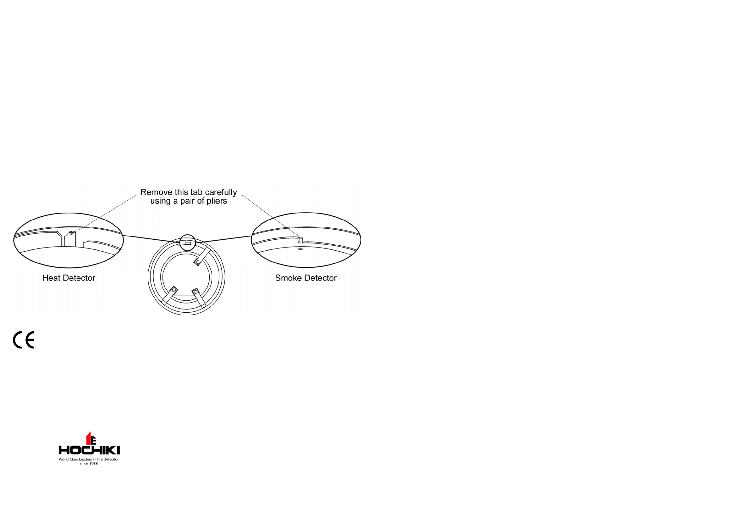
The detectors can be locked on to the base by removing a plastic lug on the underside, please refer to the diagram below. The
locked detector can then only be removed by using a special removal tool which is available from Hochiki Europe (UK) Ltd
(part number TSC-A100/ALG).
DCD-1E-IS 0832-CPD-0121 05 EN54-5 Point type heat detectors
SLR-E-IS 0832-CPD-0113 05 EN54-5 Point type heat detectors
Hochiki Europe (UK) Ltd
Grosvenor Road, Gillingham Business Park,
Gillingham, Kent, ME8 0SA, England
Telephone: +44(0)1634 260133 Facsimile: +44(0)1634 260132
Email: sales@hochikieurope.com
Web: www.hochikieurope.com
Hochiki Europe (UK) Ltd. reserves the right to alter the specification of its products from
time to time without notice. Although every effort has been made to ensure the accuracy of
the information contained within this document it is not warranted or represented by
Hochiki Europe (UK) Ltd. to be a complete and up-to-date description. Please check our
web site for the latest version of this document.
HOCHIKI INTRINSICALLY SAFE SMOKE AND HEAT DETECTORS (AND
MOUNTING BASE) INSTRUCTIONS
Products Covered: SLR-E-IS Photoelectric Smoke Detector, DCD-1E-IS Combined Rate of Rise
Heat Detector, YBN-R/4(IS) Electronics-Free Mounting Base
Introduction
These Detectors are certified by BASEEFA as suitable for use in hazardous atmospheres as detailed below. It is essential that
the detectors and base are installed and operated in conformance with the certification in order to remain safe. It is the
responsibility of the installer to ensure that the detectors and base are installed according to the certification requirements, and
it is recommended that the installation only be carried out by qualified personnel.
The YBN-R/4(IS) Base may only be used with Hochiki Intrinsically Safe specified detector heads. The use of other detector
heads is expressly forbidden and may cause fire or explosion.
Classification - SLR-E-IS
This Detector has BASEEFA certification classification according to EN 60079-11:2007 and an ATEX Classification of
II 1 G Ex ia IIC T5 -20°C<Ta<55°C. Areas suitable for installation: Category 1, 2 or 3 hazardous atmospheres, with a
maximum ambient temperature of up to 55°C.
Classification - DCD-1E-IS
This Detector has BASEEFA certification classification according to EN 60079-11:2007 and an ATEX Classification of
II 1 G Ex ia IIC T5 -20°C<Ta<55°C. Areas suitable for installation: Category 1, 2 or 3 hazardous atmospheres, with a
maximum ambient temperature of up to 55°C.
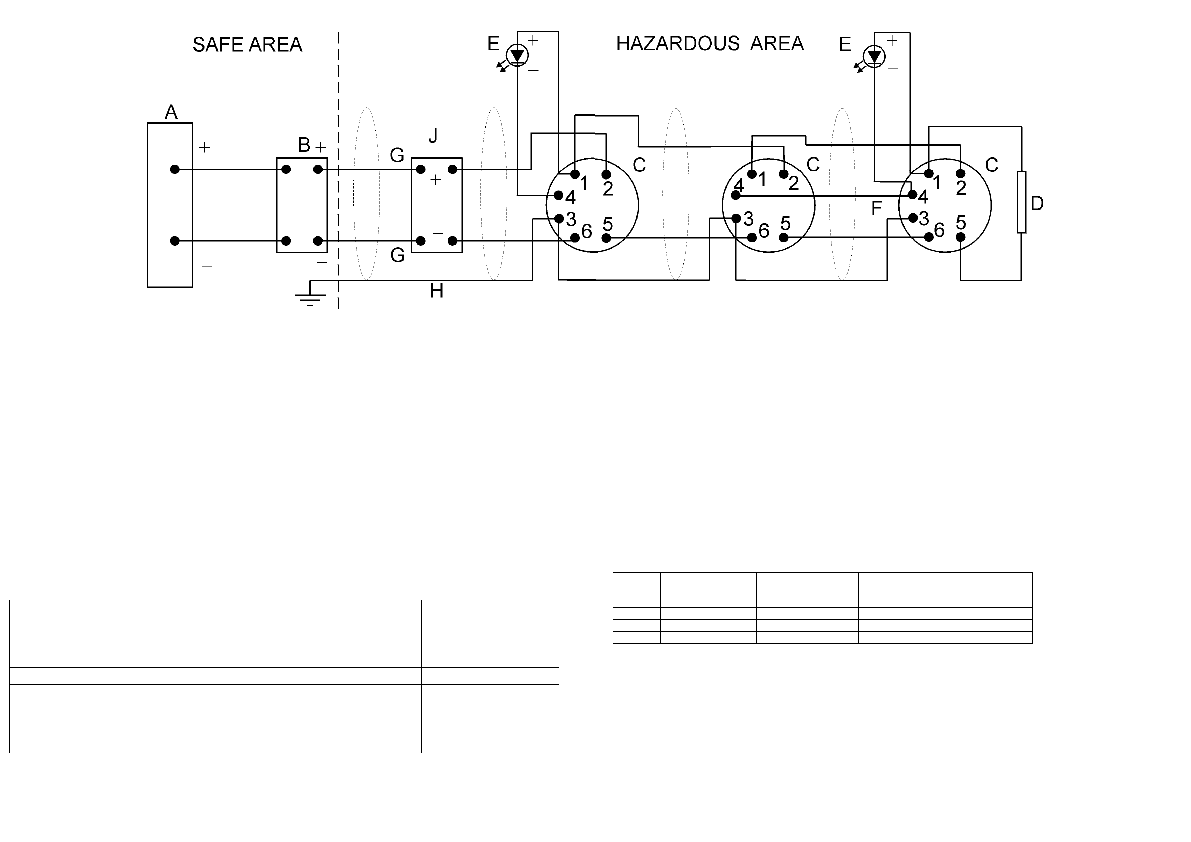
Refer to the system drawing overleaf for important information concerning installation/wiring requirements which must be
strictly observed in order to comply with BASEEFA certification. These detectors and base MUST be used with either a Zener
Diode Barrier or a Galvanic Isolator, using suitable models as detailed in the system drawing overleaf. The Zener Diode
Barrier or Galvanic Isolator should be installed according to the manufacturer's instructions.
Note
These products have been designed to
Avoid physical injury or harm by direct or indirect contact
Not produce surface temperatures of accessible parts or radiation which could cause danger
Eliminate any non-electrical dangers
Not give rise to dangerous conditions in the event of overload
Precautions
Hochiki smoke and heat detectors cannot be used to prevent a fire itself, they are intended only to detect certain characteristics
of fire. When installing the detectors, check that the location of each one has been planned according to appropriate fire
regulations and recommendations.
Hochiki detectors are suitable for indoor use only. A detector should not be installed in the following environmental conditions:
Excessive ambient temperature.
Where excessive condensation or moisture is present.
Where corrosive gas or any other harmful agent is present.
Where flammable dust or steam is present.
Where obstructions are present which could impede the flow of air to the detector.
Where mechanical stresses could affect the detector when fitted in accordance to these instructions.
Hochiki Europe (UK) Limited 2-3-0-345/ISS7/OCT10 Hochiki Europe (UK) Limited 2-3-0-345/ISS7/OCT10
Notes
1. The electrical circuit in the hazardous area must be capable of withstanding an a.c. test voltage of 500 volts to earth or
frame of the equipment, for a period of one minute without breakdown.
2. The installation must comply with National requirements.
3. The system must be marked with a durable label which should appear on or adjacent to the principal item of electrical
apparatus in the system or at the interface between the intrinsically safe and non-intrinsically safe circuits. This
marking shall include the word SYST or SYSTEM, for example “System No. BAS Ex 98D2264” or “BAS No. Ex
98D2264 SYST”.
A. Unspecified equipment except that no voltage shall exceed 250V with respect to earth.
B. EITHER:
Any BASEEFA Certified shunt safety Zener Diode Barrier with the following parameters:
30V or less
200mA or less
1W or less
The barrier earth must be connected via a high integrity connection, using an insulated conductor equivalent to a 4mm2copper
conductor, such that the impedance from the point of connection to the main power system earth is less than 1 ohm.
OR:
Any one channel from the following BASEEFA Certified Galvanic Isolators:
Type Number Um=250V I.S. Output Certificate No.
MTL 3043 2-3 5/6-7/8 Ex86B2285
MTL 40612Channel 9-8 or 12-11 1/2-3 or 4/5-6 Ex94C2040
MTL 5061 2Channel 9-8 or 12-11 1/2-3 or 4/5-6 Ex96D2426
MTL5561 2 Channel 9-8 or 12-11 1/2-3 or 4/5-6 BASEEFA09ATEX0027
P&F KFD0-CS-Ex1.51 11-12 1-2 Ex96D2152
P&F KFD0-CS-Ex2.51 11-12 or 9-8/10 1-2 or 4-5 Ex96D2152
P&F KFD0-CS-Ex1.51P 11-12 1-2 Ex96D2152
P&F KFD0-CS-Ex2.51P 11-12 or 9-8/10 1-2 or 4-5 Ex96D2152
Note: Earthing requirements as described above for Zener Diode Barriers, is not required with Galvanic Isolators.
C. Up to 20 SLR-E-IS Intrinsically Safe Photoelectric Smoke Detectors complete with YBN-R/4 IS Bases, BASEEFA Certificate
BAS01ATEX1281
OR:
Up to 20 DCD-1E-IS Intrinsically Safe Heat Detectors complete with YBN-R/4 IS Bases, BASEEFA Certificate No
BAS01ATEX1021
OR:
A combination of each type to a maximum of 20 units.
D. End-of-line resistor. The end-of-line resistor must have a body surface area of 230mm2or more.
E. Optional Remote Indicator consisting of Light Emitting Diode (LED) only. The LED must have a surface area of 230mm2or
more. The interconnecting cable to any Remote Indicator(s) is to be considered as part of the interconnecting cable described
at G below.
F. Optional interconnection for sharing a single Remote Indicator between any number of SLR-E-IS or
DCD-1E-IS/YBN-R4/IS Detector/Base combinations as shown above. The terminal 4 in each base may be interconnected as
shown at F above and a single Remote Indicator connected to any one such base. The interconnecting cable between any
terminals 4 and the wiring to any Remote Indicator is to be considered as part of the interconnecting cable described at G
below.
G. Interconnecting cable having the following maximum parameters:
Group Capacitance
C
µF
Inductance
L
mH
Inductance to Resistance ratio
L/R
µH/ohm
IIC 0.07 0.62 36
IIB 0.56 1.86 146
IIA 1.82 4.96 286
H. Optional cable screen. If used, this must only be connected to earth within the safe area and must be isolated from the
electrical circuit and must be capable of withstanding an a.c. test voltage of 500 volts for a period of one minute without
breakdown.
J. Up to 20 optional devices, for example switches such as manual call points having appropriate BASEEFA Certification for
use in the intended hazardous environment (Hochiki part no. CCP-IS) or otherwise classified as simple apparatus according to
BS EN 60079-11:2007. Such devices may be fitted with a resistor in series with the switch and /or an end-of-line resistor as
per D above. Where such a resistor is used it must have a body surface area of 230mm2or more (typical resistance 470 - 680
ohm).

This manual suits for next models

1

Other Hochiki Smoke Alarm manuals

Hochiki FireNET L@titude Series Technical manual

Hochiki

Hochiki FireNET L@titude Series Technical manual

Hochiki SLV Series User manual

Hochiki

Hochiki SLV Series User manual

Hochiki FireNET Vapor VPR-SD1 User manual

Hochiki

Hochiki FireNET Vapor VPR-SD1 User manual

Hochiki ESP FIREbeam User manual

Hochiki

Hochiki ESP FIREbeam User manual

Hochiki SLR-24 User manual

Hochiki

Hochiki SLR-24 User manual

Hochiki ALN-V Service manual

Hochiki

Hochiki ALN-V Service manual

Hochiki ALG-V User manual

Hochiki

Hochiki ALG-V User manual

Hochiki SDP-3 User manual

Hochiki

Hochiki SDP-3 User manual

Hochiki FireNET 4127 User manual

Hochiki

Hochiki FireNET 4127 User manual

Hochiki FIREbeam Xtra User manual

Hochiki

Hochiki FIREbeam Xtra User manual

Popular Smoke Alarm manuals by other brands

CLAS AC 0410 manual

CLAS

CLAS AC 0410 manual

Bentel Security 601PH manual

Bentel Security

Bentel Security 601PH manual

Ei Electronics EI 159 specification

Ei Electronics

Ei Electronics EI 159 specification

BRK electronic Smoke Alarms user manual

BRK electronic

BRK electronic Smoke Alarms user manual

Burg Wächter BURG protect SMOKE 2050 Assembly and user's manual

Burg Wächter

Burg Wächter BURG protect SMOKE 2050 Assembly and user's manual

Fire Pro FP510V user manual

Fire Pro

Fire Pro FP510V user manual

AU Tool SDT206 user manual

AU Tool

AU Tool SDT206 user manual

Onelink 1042136 user manual

Onelink

Onelink 1042136 user manual

oneConcept DOF Pro10 instructions

oneConcept

oneConcept DOF Pro10 instructions

Fire Pro FP510V user manual

Fire Pro

Fire Pro FP510V user manual

LST AI-58000-500 Specification sheet

LST

LST AI-58000-500 Specification sheet

Secutron MR-2900 installation manual

Secutron

Secutron MR-2900 installation manual

Swegon GOLD ELQZ-2-428-2 Installation

Swegon

Swegon GOLD ELQZ-2-428-2 Installation

Kidde P4010ACSCO-W user guide

Kidde

Kidde P4010ACSCO-W user guide

ADEMCO 5808 installation instructions

ADEMCO

ADEMCO 5808 installation instructions

Smartwares RM620 manual

Smartwares

Smartwares RM620 manual

Kidde SIRIUS TM0109 user guide

Kidde

Kidde SIRIUS TM0109 user guide

Telenot HD 1000 Operating and assembly instructions

Telenot

Telenot HD 1000 Operating and assembly instructions

manuals.online logo
manuals.online logoBrands
  • About & Mission
  • Contact us
  • Privacy Policy
  • Terms and Conditions

Copyright 2025 Manuals.Online. All Rights Reserved.