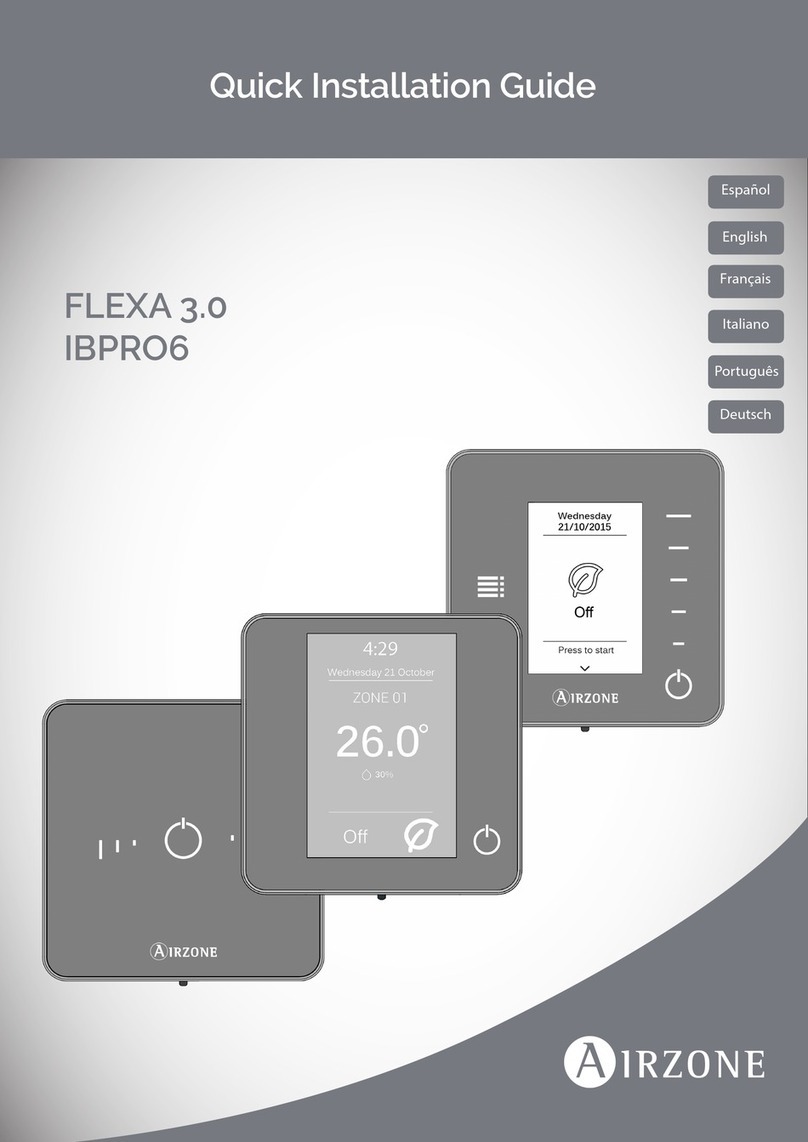
Airzone Flexa 3.0 User manual


F1 F2
230
Vac
N
AZxxxCBxMOT v1.0
DM
M8M7M6M5M4M3M2M1
CAN
IU
AZ2 AZ3
AZ1
AI1 DI1
O2
ON/OFF Module
N L O1
P3 SW1
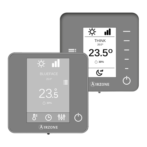
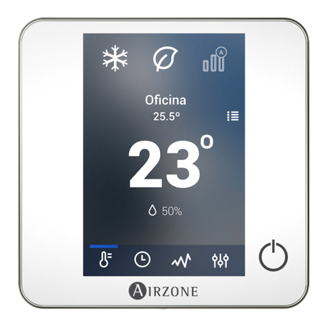
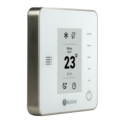
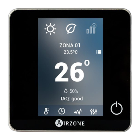
AZCE6BLUEZEROC AZCE6THINKR
AZCE6LITEC
AZCE6OUTPUT8
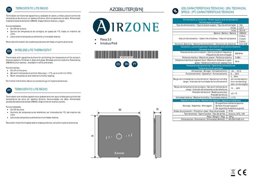
AZCE6LITER
RINT CPRC CPCC

1
Content
ENVIRONMENTAL POLICY_________________________________________________________________________ 2
BEFORE STARTING__________________________________________________________________________________ 3
SYSTEM INSTALLATION____________________________________________________________________________ 4
>control board Installation_______________________________________________________________ 4
>Thermostat installation _________________________________________________________________ 4
>Connecting the motorized elements _________________________________________________ 5
>Connection to the indoor unit__________________________________________________________ 5
>Communications gateway option _______________________________________________ 5
>Control gateway option ___________________________________________________________ 5
>O1 port option _______________________________________________________________________ 5
>Other peripherals_________________________________________________________________________ 6
>Power supply to the system ___________________________________________________________ 6
CHECKING THE INSTALLATION ___________________________________________________________________ 7
INITIAL CONFIGURATION __________________________________________________________________________ 8
>Airzone Blueface zero___________________________________________________________________ 8
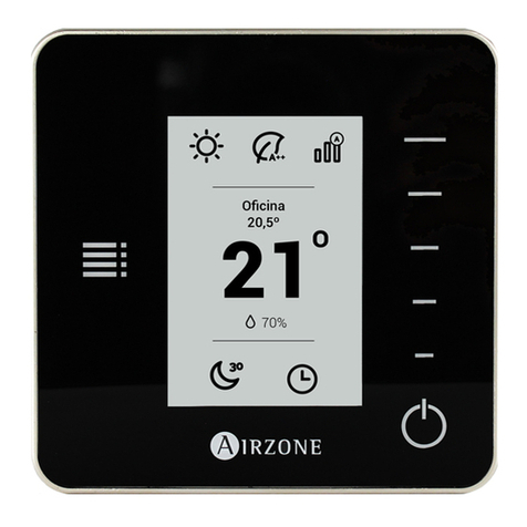
>Airzone Think _____________________________________________________________________________ 9
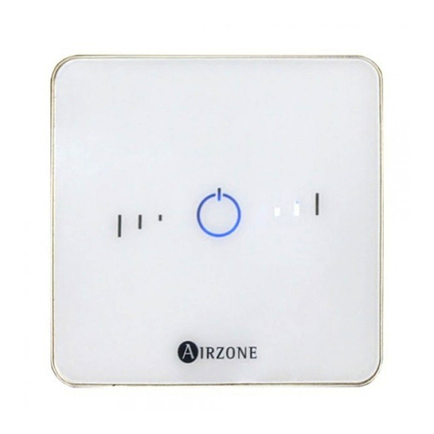
>Airzone Lite________________________________________________________________________________ 11
>Checking the initial conguration_____________________________________________________ 12
>System reset ______________________________________________________________________________ 12
>Zone reset _________________________________________________________________________________ 12
SYSTEM ADVANCED SETTINGS __________________________________________________________________ 13
>Airzone Blueface zero___________________________________________________________________ 13
>Airzone Think _____________________________________________________________________________ 13
>Airzone Cloud _____________________________________________________________________________ 13
>System parameters______________________________________________________________________ 14
>Zone parameters _________________________________________________________________________ 17
>Production parameters__________________________________________________________________ 18
EN

2
EN
Environmental Policy
• Never dispose of this equipment with household waste. Electrical and electronic
products contain substances that can be harmful to the environment if not
properly handled. The crossed-out waste bin symbol indicates separate collection
of electrical devices, which must be separated from other urban waste. For correct
environmental management, at the end of its useful life the equipment should be
taken to the collection centers provided for this purpose.
• The parts that make it up can be recycled. Therefore, please respect the regulations
in force regarding environmental protection.
• If you replace the equipment, the original equipment must be returned to your
dealer or deposited at a specialized collection center.
• Violations are subject to the penalties and measures stipulated in environmental
protection law.

3
• The system must be installed by a qualied technician.
• This product must not be modied or disassembled under any circumstances.
• Do not handle the system with wet or damp hands.
• In the case of any malfunction of this appliance, do not repair it yourself. Contact the
sales distributor or service dealer for repair or disposal of the product.
• Check that the HVAC installation has been installed according to the manufacturer's
requirements, complies with local regulations in force and is working correctly
before you install the Airzone system.
• Place and connect the elements in your installation in accordance with current
regulations covering electrical installations.
• All connections must be made with the power supply completely turned off.
• Take care not to short circuit any of the system's connections.
• Please refer carefully to the wiring diagram and these instructions when wiring.
• Connect all wiring securely. Loose wiring may cause overheating at the connection
points and is a possible re hazard.
• Do not locate the Airzone communication bus close to power lines, uorescent
lights, actuators, etc. as this may cause interference in communications.
• The connection to the external power supply must include a main switch or other
method of disconnection that includes a constant separation for all polarities,
in accordance with appropriate local and national regulations. The system will
Before Starting
automatically restart if the power supply is turned off. Use separate circuits for the
unit that is to be controlled and the power supply to the system.
• Check the polarity of each device's connectors. A wrong connection can seriously
damage the product.
• To connect to the system, use Airzone cable: four-wire cable (2x0.22 mm2twisted
shielded wires for data communications and 2x0.5mm2wires for power supply).
• A Blueface zero thermostat must be used to enable all the Airzone system
functionalities.
• Recommendations for the placing of the thermostats:
• For equipment using R32 refrigerant, verify the compliance with the local
refrigerant regulation.
• The room size installation requirements mentioned in the manual of the ducted
indoor unit, to which the Easyzone is connected, remain applicable to each and
every separate room served by the Airzone unit.
• Ducts connected to Easyzone shall not contain a potential ignition source.
EN
4
EN
System Installation
CONTROL BOARD INSTALLATION
1. Locate the control board close to the
unit to be controlled.
2. Unscrew the cover securing the back
part to the wall.
3. Make all the connections and screw the
cover again.
THERMOSTAT INSTALLATION
1. Remove the back of the thermostat.
2. Fix the back of the thermostat to the
wall.
3. Connect the main control board to any
of the three terminals AZ1, AZ2 o AZ3.
Fix the cables using the main control
board turrets.
If your thermostat is a wireless
thermostat, insert the CR2450 button
battery.
4. Place the display over the xed support.
5. Place the anti-vandalism rods (optional)
to better hold the thermostat in place.
AZ1-AZ2-AZ3AZ1-AZ2-AZ3

5
EN
CONNECTING THE MOTORIZED ELEMENTS
Connect each output (M1...M8) to the
actuator of its corresponding control
zone. Do not connect more than two
actuators per output. Use the Airzone cable
(2x0.75 mm2) for the connection. Highest
recommended length 20 m.
CONNECTION TO THE INDOOR UNIT
IU
Communications gateway option
Connect the communication gateway
to the IU port of the main control board.
Follow the instructions of the gateway
datasheet. It is recommended to install the
thermostat of the unit.
Control gateway option
Connect the communication gateway to
the IU port using Airzone wire 2x0.22 mm2
(use the shield only on the connector of the
main control board).
O1 port option
Use the main control board O1 port to
perform the start-stop of the unit following
the manufacturer's instructions. Imax 1 A,
Vmax 24 / 48 Vdc.
IU
OFF
ON
O1

6
EN
OTHER PERIPHERALS
Follow the instructions on their technical data sheet.
Important: For elements with external power supply at 110/230 VAC, it is only necessary to
connect poles "A" and "B" of the bus for communications.
POWER SUPPLY TO THE SYSTEM
Use input power supply to power the main
control board at 110/230 VAC as well as
any other control elements that require
external power supply. Use 3x1.5 mm² cable.
For added security, secure the wires using
the turret.
The connection to the external power
supply must include a main switch or
other method of disconnection that
includes a constant separation for all
polarities, in accordance with appropriate
local and national regulations. The system
will automatically restart if the power
supply is turned off. Use separate circuits
for the unit that is to be controlled and the
power supply to the system.
Once all the connections have been made,
make sure the cover of the main control
board is correctly replaced.

7
EN
Checking the Installation
Check the following items:
1. Status of the main control board LEDs and of the other control elements connected.
Consult the Self-diagnostics section on each element's technical fact sheet.
2. The main control board LEDs indicating the opening of motorized elements light up in
sequence.
3. Power supply to wired and wireless thermostats.
Blinking
Steady
Switches
M1...M8M1...M8
(Green) Damper
opening
(Red) Damper
closing
AZxxxCBxMOT v1.0
DM
M8M7M6M5M4M3M2M1
CAN
IU
AZ2 AZ3
AZ1
AI1 DI1
O2
ON/OFF Module
D3
D8
D9
D80
D79
D37
D39
D36
D38
D41
D43
D40
D42
D45
D47
D44
D46
D55
D57
D54
D56
D18
D6
D5D4
D2
D1
D19
D11
D10
D7
N L O1
SW1

8
EN
Initial Configuration
AIRZONE BLUEFACE ZERO
Stages to be controlled:
• Air
• Radiant
• Combined
Master: Allows the control of
all installation parameters.
Zone: Only allows the control
of the zone parameters.
Select the zone associated to
this thermostat. Each zone
has a corresponding control
output (actuator output or
radiant element control relay
output).
Languages:
• Spanish
• English
• French
• Italian
• Portuguese
• German
The system allows you to
associate more than one
control output to a zone
if needed. It is therefore
possible to manage several
control outputs from a
single thermostat.
Finish the process, access
the advanced settings
and/or activate the basic
function (the latter allows
on/off, speed setting,
operation mode setting and
temperature setting).

9
EN
AIRZONE THINK
Check that the signal range
is optimal (minimum 30%).
Start the search for the
wireless channel.
Select the zone associated to
this thermostat. Each zone
has a corresponding control
output (actuator output or
radiant element control relay
output).
Wireless Think
Open the wireless
association channel. To do
so, click SW1. Once opened,
you have 15 minutes to
perform the association.
You can also open the
wireless association channel
through the Blueface zero
thermostats.
Wired Think
Go to step 4.
IMPORTANT: Remember
not to have more than one
channel open in the same
installation at the same
time.
SW1
Languages:
• Spanish
• English
• French
• Italian
• Portuguese
• German

10
EN
The system allows you to associate more than one control
output to a zone if needed. It is therefore possible to manage
several control outputs from a single thermostat.
Master: Allows the control of
all installation parameters.
Zone: Only allows the control
of the zone parameters.
*Stages to be controlled:
• Air
• Radiant
• Combined
Finish the process, access
the advanced settings
and/or activate the *basic
function (the latter allows
on/off, speed setting,
operation mode setting and
temperature setting).
*Not available on 3.5.0 or later version AZCE6THINKR

11
EN
AIRZONE LITE
Select the zone associated to this
thermostat by raising the microswitch
corresponding to the zone.
Select other control outputs associated
to the zone if necessary. The zone address
will be the one with the lowest number
selected (for example, associated output 8
to the zone address 7).
Wireless Lite
Open the wireless association channel. To
do so, click SW1. Once opened, you have
15 minutes to perform the association.
You can also open the wireless association
channel through the Blueface zero
thermostats.
IMPORTANT: Remember not to have
more than one channel open in the same
installation at the same time.
Wired Lite
Go to step 3.
If you want to congure other thermostat
settings you must access the zone
advanced settings menu from an Airzone
Blueface zero thermostat.
The icon will blink 5 times in green to
indicate that the association is correct. If
the icon blinks once in red, this indicates
that the zone is occupied, and if it blinks
twice in red, it means that the thermostat
is not in signal range.
Remember: Should it be necessary to
change the zone number, rst reset the
thermostat and initiate the association
sequence.
SW1

12
EN
CHECKING THE INITIAL CONFIGURATION
Check the following items:
1. AC unit-system communication: Set the Airzone system to an operation mode other
than Stop and turn on the zone to generate demand. Verify that the mode imposed on
the master thermostat appears on the indoor unit thermostat and that the set-point
temperature changes on the same.
2. AC unit-system communication: Set the Airzone system to Stop mode and verify that the
AC unit turns off and dampers open.
3. Opening/closing of the dampers and control outputs: Turn on and generate demand in
all the zones. Then turn each zone off and on to check that the associated control outputs
are correct.
4. Check that the static pressure in the ducted AC unit is in accordance with the conditions of
the airow distribution network in which it is installed (see the manufacturer's manual for
the AC unit if you need to modify this parameter).
SYSTEM RESET
If you need to return the system to factory
settings, press and hold SW1 until LED D19
stops blinking. Wait for the LEDs to return
to their normal status and then repeat the
initial conguration.
SW1
ZONE RESET
For Blueface zero and Think thermostats, follow the steps indicated in the Advanced settings
menu, Zone parameters.
For Lite thermostats, lower all microswitches and replace the thermostat in its base. The icon
will blink twice in green conrming that the reset has been completed.

13
EN
System Advanced Settings
AIRZONE BLUEFACE ZERO
AIRZONE THINK
Press and hold
Press and
hold
Press and
hold
Advanced system conguration can be performed from the Airzone Cloud application (see
Airtools section of the Airzone Cloud Installation Manual).
The following parameters can be congured:
• System parameters
• Zone parameters
• Production parameters
AIRZONE CLOUD

14
EN
SYSTEM PARAMETERS
• System address. (Not available on systems with BACnet gateway) This allows you to dene
the number of the system in your installation. By default, it displays the value 1. The system
will show the free address values with a maximum value of 99.
If you have address 1 and have an Airzone production control board (AZX6CCPGAWI) in the
installation, you can use the Supermaster function, which imposes the operation mode of
system 1 on the other systems connected to the AZX6CCPGAWI in a semi-forced way:
• Temperature range1.This allows you to select the maximum temperature for heating mode
(19 – 30 °C) and minimum temperature for cooling mode (18 – 26 °C), in steps of 1 °C. If you
want, you can disable any of the modes. By default, the maximum heating temperature is
set to 30 °C and the minimum cooling temperature to 18 °C.
• Combined stage1. (Only available in installations with AZCE6OUTPUT8 modules) This
allows you to activate/deactivate the combined stage of the "Control stages" parameter in
the user "Zone settings" menu.
• Hysteresis Cong1. This denes the temperature differential between the room
temperature and the set-point temperature to begin to apply the RadianT algorithm, which
aims to prevent underoor heating installations overheating. In installations with radiators,
set this value to 0 °C. By default, it is set to 0 °C.
• Type of opening*1. This allows you to enable/disable the proportionality of the system
dampers. Proportionality scales the opening or closing of the damper in 4 steps according
to the temperature demand of the zone, adjusting the zone airow rate. By default, it is set
to All/Nothing.
Operation mode of system 1 Available operation modes of the
other systems
*Note: Changing this parameter affects all motorized dampers in the installation. It is not
recommended for RINT and RIC smart grilles.
1Parameters not available in Airzone Blueface zero thermostats

15
EN
• Return temperature1. (Not available on 3.5.0 or later version AZCE6THINKR) (Only
available in installations with AZX6SONDPROTEC protection probe) This allows you to
dene the system's cut-off temperatures for the protection of the AC unit in heating mode
(32 °C, 34 °C and 36 °C) and cooling mode (6 °C, 8 °C and 10 °C). By default, the system's
heating cut-off temperature is set to 34 °C and the cooling cut-off temperature is set to 8 °C.
• Radio channel. This allows you to enable/disable the system's wireless association channel.
• Reset system. (Only available for Airzone Blueface zero master thermostats) This allows
you to reset the system by returning it to factory settings. To recongure the thermostats,
go to the "Initial conguration" section.
• Information. (Only for Airzone Think thermostats) This allows you to display information
about:
- Zone: rmware, zone, association, actuator or communications status.
- System: rmware, IAQ rmware, settings and information on system and installation
controllers.
- Devices: indicates the elements connected to the system.
- Webserver: rmware, IP address, gateway, MAC and PIN.
• Q-Adapt1. (Only for Airzone Think thermostats)
1. In direct expansion units. This allows you to dene the airow control algorithm that
best ts the duct installation. The options available are:
- Maximum: the system operates at maximum speed regardless of the number of zones.
- Power: the system operates at a higher speed than in Standard mode to ensure airow
is increased.
- Standard (by default): the system changes speed depending on the number of zones.
- Silence: the system operates at a lower speed than in Standard mode to improve noise
reduction.
- Minimum: the system operates at minimum speed regardless of the number of zones.
2. In fancoil units 0-10V. This allows you to set the minimum (1.5 V by default) and
maximum (10 V by default) working voltage of the fan of the controlled AC unit, in 1 V
steps. The minimum voltage will correspond to the desired minimum speed of the AC
unit and the maximum voltage will correspond to the maximum speed. The average
speed will correspond to the midpoint between the two.
• Relay settings1. (Only for Airzone Cloud) This allows you to change the operation logic of the
main control board's CMV/Boiler relay. By default, it is set to CMV.
• Standby mode1. (Only for Airzone Cloud) Conguration of the operation logic of the
motorized elements when there is no demand on the system. This is disabled by default. If
enabled, from Airzone Cloud only the following can be congured:
- Standby mode for cooling: allows you to activate or deactivate Standby in cooling mode
- Standby mode for heating: allows you to activate or deactivate Standby in heating mode
- Heating Hysteresis: sets a hysteresis value in heating mode (by default 3 °C)
- Cooling Hysteresis: sets a hysteresis value in cooling mode (by default 1°C)
• Filter maintenance1. (Only for Airzone Cloud) It is used to enable or disable the warning,
edit hours of operation or reset the lter maintenance count.
1Parameters not available in Airzone Blueface zero thermostats

16
EN
• Protection mode1. (Only for Airzone Cloud) This allows you to disable the delay in the
closing of the motorized elements.
• BACnet1. (Only in installations with AZX6BACNET) This parameter shows the device ID,
uplink port, IP address, subnet mask and gateway IP and allows you to modify them. Click
on the desired value, modify the parameters and click on the option to conrm. The default
values are:
- Device ID: 1000
- Port: 47808
- IP address: DHCP
• Centralized control. This allows you to dene whether or not your installation has a
centralized controller. By default, it will be congured as deactivated.
1Parameters not available in Airzone Blueface zero thermostats
Other manuals for Flexa 3.0
1
This manual suits for next models
1
Table of contents
Languages:
Other Airzone Thermostat manuals

Airzone
Airzone UNO User manual

Airzone
Airzone AZCE6LITER User manual

Airzone
Airzone FLEXA 3.0 IBPRO6 User manual

Airzone
Airzone OneZone User manual

Airzone
Airzone ZS6 User manual

Airzone
Airzone FREE User manual

Airzone
Airzone ACUAZONE IBPRO32 User manual

Airzone
Airzone OneZone User manual

Airzone
Airzone Flexa 3.0 User manual

Airzone
Airzone RADIANT365 User manual