Aiwa XD-PG700 User manual

8C-AVA-903-01
020215AMK-H-L U
DVD PLAYER
PLATINA DVD
XD-PG700
OPERATING INSTRUCTIONS
MANUAL DE INSTRUCCIONES
En
(English)
E
(Español)
For assistance and information,
call toll free 1-800-BUY-AIWA.
(United States and Puerto Rico)
Model No. Serial No. (Lot No.)
XD-PG700
Owner’s record
For your convenience, record the model number and serial
number (you will find them on the rear of your set) in the
space provided below. Please refer to them when you
contact your Aiwa dealer in case of difficulty.

2
ENGLISH
ENGLISH
WARNING
TO REDUCE THE RISK OF FIRE OR
ELECTRIC SHOCK, DO NOT EXPOSE THIS
APPLIANCE TO RAIN OR MOISTURE.
Explanation of Graphical Symbols:
The lightning flash with arrowhead symbol,
within an equilateral triangle, is intended to
alert the user to the presence of uninsulated
"dangerous voltage" within the product’s en-
closurethatmaybeofsufficientmagnitudeto
constitute a risk of electric shock to persons.
Theexclamationpointwithinanequilateral
triangle is intended to alert the user to the
presenceofimportantoperatingandmain-
tenance (servicing) instructions in the
literature accompanying the appliance.
PRECAUTIONS
Read the Operating Instructions carefully and completely
before operating the unit. Be sure to keep the Operating
Instructions for future reference.All warnings and cautions
in the Operating Instructions and on the unit should be
strictly followed, as well as the safety suggestions below.
Important
This unit is designed for the NTSC color system only.
Installation
1Water and moisture — Do not use this unit near water,
such as near a bathtub, sink, swimming pool, or the
like.
2Heat — Do not use this unit near sources of heat,
including heating vents, stoves, or other appliances that
generate heat. This unit should not be placed in
temperatures less than 5˚C (41˚F) or greater than 35˚C
(95˚F).
3Mounting place — Place the unit:
-on a flat , even surface
-away from strong magnetic fields
-at least one meter away from any radios or receivers
Do not place heavy objects on the unit.
4Ventilation —Theunit shouldbe situatedwith adequate
spacearound it sothat properheatventilation isassured.
Allow a clearance of 10 cm (4 in.) from the rear and the
top of the unit, and 5 cm (2 in.) from each side.
-Do not place the unit on a bed, rug, or similar surface
that may block the ventilation openings.
-Donot installthe unit ina bookcase,cabinet, or airtight
rack where ventilation may be impeded.
-To avoid internal heat build-up, do not cover the
ventilation openings on the rear panel.
5Foreign objects and liquid — Be careful that foreign
objects or liquid do not enter the unit through the
ventilation openings.
6Carts and stands — The unit should be
movedwith care whenplaced ormounted
on a stand or cart.
Sudden stops, excessive force, or an
unevensurface may causethe unit orcart
to fall over.
7Condensation —Moisture mayform on thepickup lens
when:
-This unit is moved from a cold spot to a warm spot
-Aheating system has just been turned on
-The unit is used in a very humid room
-The unit is cooled by an air conditioner
When this unit has condensation inside, it may not
function normally. Should this occur, leave the unit for a
few hours, then try to operate again.
Electric power
1Power sources — Connect this unit only to power
sources specified in the Operating Instructions, and as
marked on the unit.
2AC power cord
-When disconnecting theAC power cord, pull it out by
the AC power plug. Do not pull the cord itself.
-Never handle the AC power plug with wet hands, as
this could result in fire or electrical shock.
-Power cords should be firmly secured to avoid being
severelybent, pinched,or walked upon. Pay particular
attentionto the cordfrom theunit to the power socket.
-Avoid overloading AC power plugs and extension
cords beyond their capacity, as this could result in
fire or electrical shock.
3When not in use — Unplug the AC power cord from
the AC outlet if the unit will not be used for several
months or more. When the cord is plugged in, a small
electrical current continues to flow into the unit, even if
the power is turned off.
4In case of lightning — Immediately disconnect theAC
power cord from the AC outlet.
Maintenance
Clean the unit only as recommended in the Operating
Instructions.
Damage requiring service
Have this unit serviced by a qualified service technician if:
-The AC power cord or plug has been damaged
-Aforeign object or liquid has entered the unit
-The unit has been exposed to rain or water
-The unit does not seem to operate normally
-The unit exhibits a marked change in performance
-The unit has been dropped, or the cabinet has been
damaged
DO NOT OPEN THE CABINET AND ATTEMPT TO
SERVICETHE UNIT YOURSELF.

ENGLISH
3
INTRODUCTION
En
Features
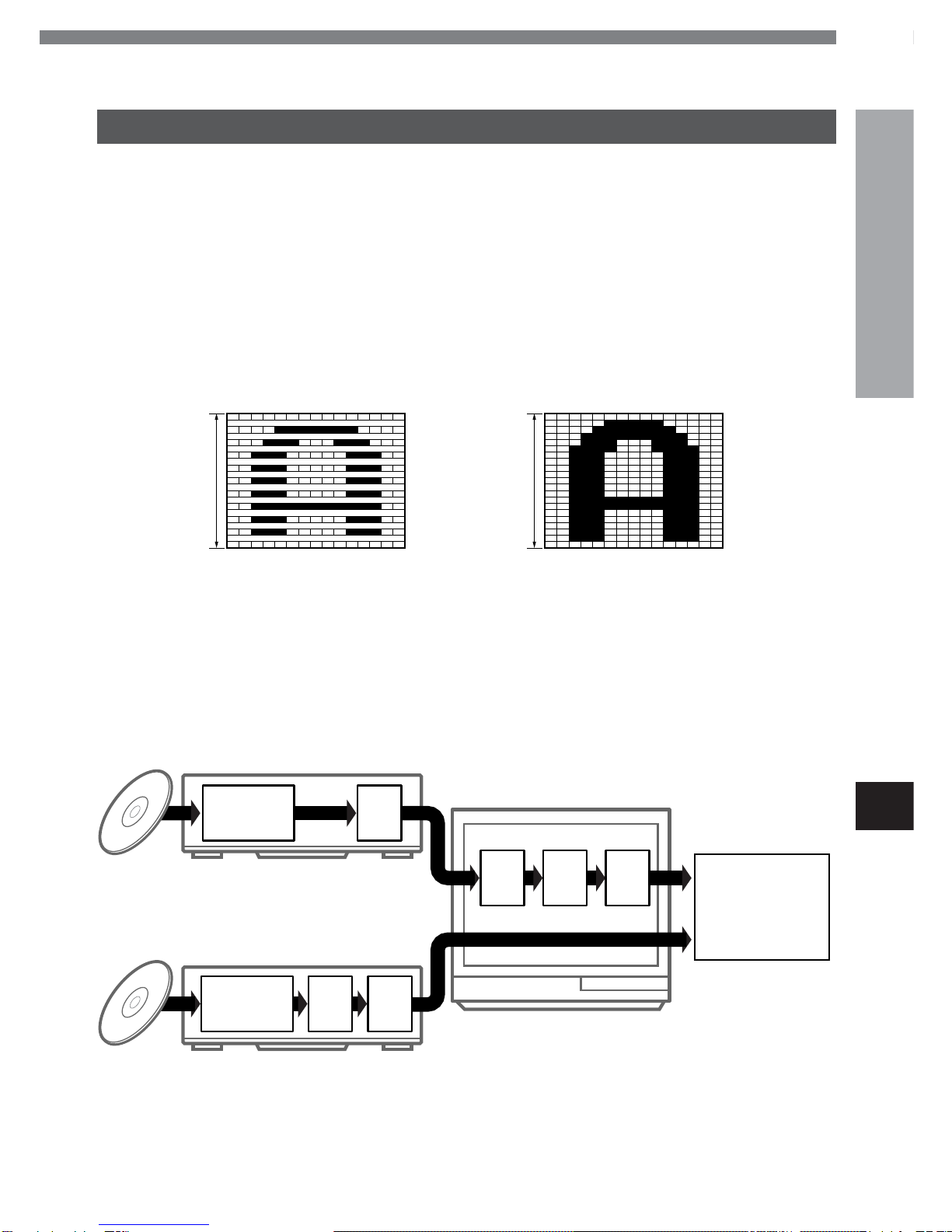
High quality digital audio and images
•Including a progressive scan conversion circuit
•The linear PCM sound of a 96 kHz/24 bit creates audio
quality superior to that of audio CDs.
•Compatible with audio CDs, as well as DVDs
•MP3 playback
Accessory checklist
Remote control (1)
Audio cord (1)
Video cord (1)
Operating Instructions
Table of Contents
Introduction
Precautions ...............................................................2
Before Use.................................................................4
Disc symbols used in this manual...................4
Supported disc formats ....................................4
Disc-related terms..............................................5
Handling the unit................................................5
Handling discs....................................................5
Cleaning the unit................................................5
Cleaning discs....................................................6
Storing discs ......................................................6
Notes on copyright ............................................6
Remote control.................................................. 6
General information on progressive scan ......7
Parts and Controls .................................................. 8
Front panel......................................................... 8
Remote control.................................................. 8
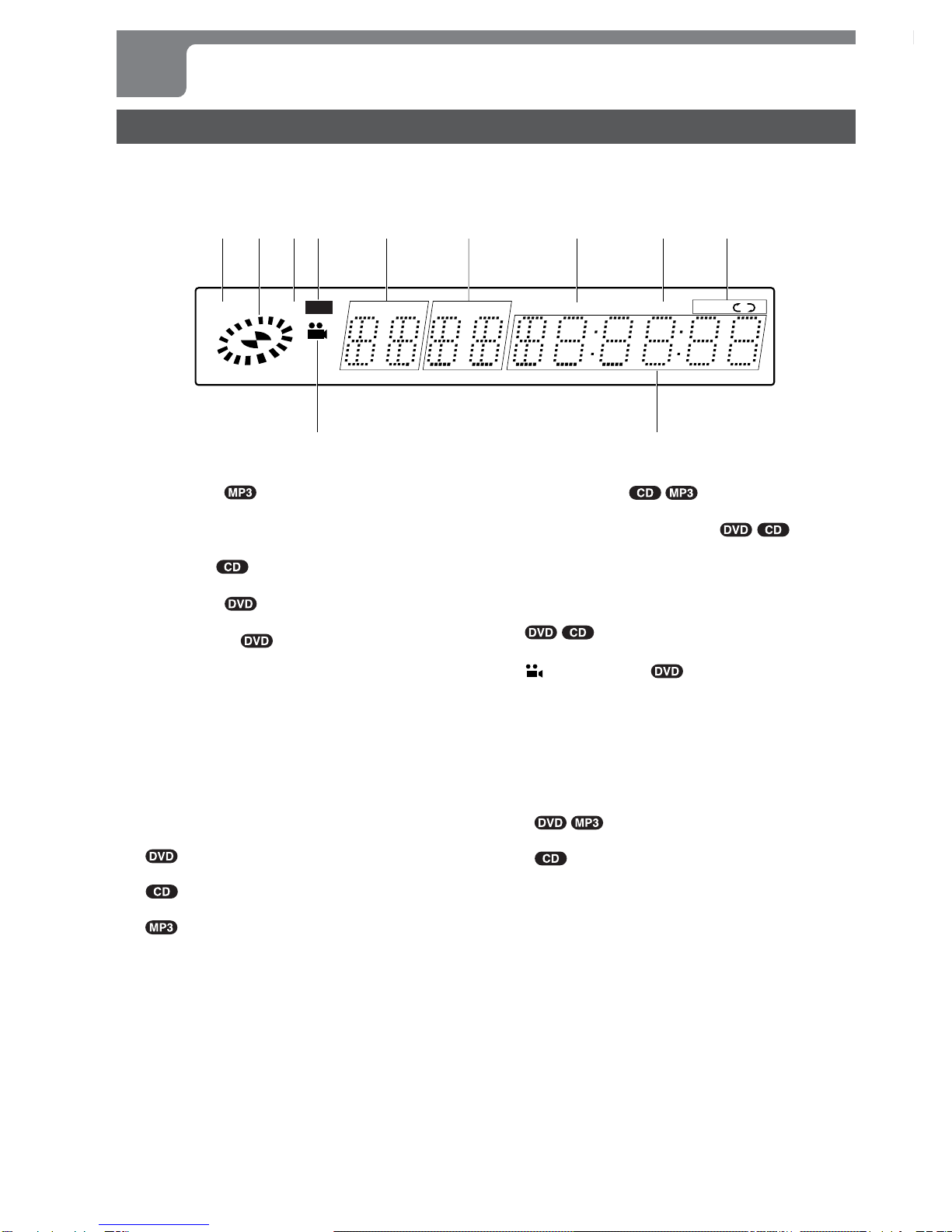
Display window ............................................... 10
Preparations
Connections........................................................... 11
Connecting to a TV.......................................... 11
Connecting to audio equipment.................... 12
A-1 Connecting to a TV ...................................13
A-2 Connecting to a TV equipped with
an S-video input connector .......................14
A-3 Connecting to a TV or monitor with
component video input connectors ........ 15
BConnecting to a TV and an amplifier
with a digital input jack..............................16
CConnecting to a TV and a stereo
system .........................................................17
DConnecting to a TV and an AV receiver
equipped with a Dolby Digital (AC-3)
decoder .......................................................18
EConnecting to a TV and an AV receiver
equipped with a DTS decoder...................19
FConnecting to a TV and an AV receiver
equipped with a Dolby Pro Logic
decoder .......................................................20
Basic Operations
Playback ................................................................. 21
Still (pause)...................................................... 22
Frame advance ................................................ 22
Resuming playback ........................................ 22
Fast forward and fast reverse........................ 23
Slow playback.................................................. 23
Skipping ........................................................... 23
Basic operation of the OSD (On-Screen
Display) menu ........................................... 24
Description of each OSD menu item ............ 25
More Features
Search ..................................................................... 26
Title search ...................................................... 26
Chapter search ................................................ 27
Time search ..................................................... 27
Mark search ..................................................... 28
Zooming and Changing the Angle ...................... 29
Zooming the picture ....................................... 29
Changing the angle......................................... 29
Random and Repeat Playback............................. 30
Random playback ........................................... 30
Repeat playback .............................................. 30
Repeating a section between two
specified points (A-B repeat) .................. 31
Programmed Playback.......................................... 32
Creating a 3D Surround Effect............................. 34
Changing the Audio Track/Channel..................... 35
Displaying and Changing Subtitles .................... 36
Playing an MP3 Disc ............................................. 37
Notes on MP3 discs ........................................ 37
Glossary ........................................................... 37
Basic operations of MP3 playback ............... 38
OSD (On-Screen Display) menu for
the MP3 disc .............................................. 39
Other MP3 disc operations ............................ 39
As Necessary
Changing Setup Values......................................... 40
Basic operations ............................................. 40
Disc Audio........................................................ 41
Disc Subtitle .................................................... 42
Disc Menu ........................................................ 42
Rating ............................................................... 43
Country Code .................................................. 44
TV Aspect......................................................... 44
Menu Language............................................... 45
Progressive Scan ............................................ 46
Digital Audio Output ....................................... 46
Others ............................................................... 47
Country codes ................................................. 48
Language codes.............................................. 50
Troubleshooting .................................................... 51
Specifications ........................................................ 52

4
ENGLISH
Before Use
Supported disc formats
This unit can play discs with the following marks.
DVD
(8-cm and 12-cm discs)
Audio CD
(8-cm and 12-cm discs)
In addition, the unit can play DVD-R and DVD-RW discs
recorded in Video mode, and CD-R and CD-RW discs that
contain audio titles or MP3 files.
NOTES
•The unit can play DVD-R/RW discs recorded in Video
modeonly.DVD-R/RWdiscs recordedinVideoRecording
(VR) mode cannot be played on the unit.
•Depending on theconditions ofthe recording equipment,
someDVD-R/RWdiscs cannot beplayed onthe unit even
if they have been recorded in Video mode.
•Some DVD-R/RW discs cannot be played on the unit
due to scratches on the surface or warp of the disc, etc.
•Becauseof their relativelylow reflectance,DVD-RWdiscs
are more likely not to be playable on the unit than DVD-
R discs.
•Audio CDs which contain copy protection signals cannot
be played on the unit.
•Depending on the conditions of the recording equipment
or the CD-R/RW disc itself, some CD-R/RW discs cannot
be played on the unit.
•The unit cannot play the CD-R/RW discs that contain no
data, or contain different kinds of formatted data other
than MP3. For more information about MP3, see page
37.
•Do not attach any seal or label to either side (the labeled
side or recorded side) of a disc.
•Do not use irregular shaped CDs (e.g. heart-shaped or
octagonal). It may result in malfunctions.
Notes on color system
This unit is designed for the NTSC color system only.
The materials for DVD discs are recorded in the PAL and
NTSC color systems.
Select the DVD recorded in the NTSC color system.
Notes on DVDs
Some playback operations of DVDs may be intentionally
fixed by software manufacturers. As this unit plays DVDs
according to disc content designed by the software
manufacturer, some playback features of the unit may not
be available, or other functions may be added.
Refer also to the instructions supplied with the DVDs.
SomeDVDs made forbusiness purposesmaynot beplayed
on the unit.
Please read the following before operating the unit.
Disc symbols used in this manual
Althoughthis unit canplay DVDs,audioCDs andMP3discs,
some of the functions are restricted depending on the type
of disc.
The following symbols are used to make distinctions.
No symbols:Thefunction works forDVDs, audio CDsand
MP3 discs.
:Indicatesa functionordisplay forDVDs only.
: Indicates a functionor displayfor audioCDs
only.
: Indicates a functionor displayfor MP3 discs
only.
Playback of MP3 discs is different from that of other
kinds of discs. For information about playing MP3 discs,
see "Playing an MP3 Disc" on page 37.

ENGLISH
5
INTRODUCTION
En
Region code of the DVD player and DVDs
ThisDVD playeris designed andmanufactured forplayback
of region "1" encoded DVD software. The region code on
thelabels of some DVD discsindicates which type of player
can play those discs. This unit can play only DVD discs
labeled "1" or "ALL." If you try to play any other discs, the
message "Check Regional Code" will appear on the TV
screen. Some DVD discs may not have a region code label
even though their playback is prohibited by area limits.
Disc-related terms
Title
The longest section of a picture or a musical piece on a
DVD, a movie for a picture piece on video software, or an
album for a musical piece on audio software. Each title is
assigned a title number enabling you to locate the title you
want.
Chapter
Sections of a picture or a musical piece that are smaller
than titles.
A title is composed of several chapters. Each chapter is
assigned a chapter number, enabling you to locate the
chapter you want. Depending on the disc, no chapters may
be recorded.
Track
Sections of a musical piece on an audio CD. Each track is
assigned a track number, enabling you to locate the track
you want.
Handling the unit
When shipping the unit
The original shipping carton and packing materials come
in handy. For maximum protection, repack the unit as it
was originally packed at the factory.
When setting the unit
The picture and sound of a nearby TV, VCR, or radio may
be distorted during playback. In this case, position the unit
away from the TV, VCR, or radio, or turn off the unit after
removing the disc.
To keep the surface clean
Do not use volatile liquids, such as insecticide spray, near
the unit. Do not leave rubber or plastic products in contact
with the unit for a long period of time. They will leave marks
on the surface.
Handling discs
Do not touch the playback side of the disc.
Hold the disc by the edges so that fingerprints will not get
on the surface.
Do not stick paper or tape on the disc.
Cleaning the unit
To clean the cabinet
Use a soft, dry cloth. If the surfaces are extremely dirty,
use a soft cloth lightly moistened with a mild detergent
solution. Do not use strong solvents, such as alcohol,
benzine, or thinner, as these might damage the surface of
the unit.
To obtain a clear picture
The DVD player is a high-tech, precision device. If the
optical pick-up lens and disc drive parts are dirty or worn
down, the picture quality will be poor.
Regular inspection and maintenance are recommended
after every 1,000 hours of use. (This depends on the
operating environment.)
For details, please contact your Aiwa dealer.
CONTINUE
CONTINÚE

6
ENGLISH
Cleaning discs
Fingerprints and dust on the disc can cause poor picture
quality and sound distortion. Before playing, clean the disc
with a clean cloth. Wipe the disc from the center out.
Do not use strong solvents such as alcohol, benzine,
thinner, commerciallyavailable cleaners,or anti-staticspray
intended for analog records.
Storing discs
After playing, store the disc in its case.
Do not expose the disc to direct sunlight or sources of heat,
or leave it in a parked car exposed to direct sunlight, as
there may be a considerable temperature increase inside
the car.
Notes on copyright
It is forbidden by law to copy, broadcast, show, broadcast
via cable, play in public, or rent copyright material without
permission.
This product features the copy protection function
developed by Macrovision. Copy protection signals are
recorded on some discs. When recording and playing the
pictures of these discs on a VCR, the picture noise will
appear.
This product incorporates copyright protection technology
that is protected by method claims of certain U.S. patents
and other intellectual property rights owned by Macrovision
Corporation and other rights owners. Use of this copyright
protection technology must be authorized by Macrovision
Corporation, and is intended for home and other limited
viewing uses only unless otherwise authorized by
Macrovision Corporation. Reverse engineering or
disassembly is prohibited.
Before Use (continued)
Remote control
Installing batteries
Detach the battery cover on the rear of the remote control,
and insert two R03 (size AAA) batteries with 0and 9
aligned correctly.
R03 (AAA)
When to replace the batteries
The maximum operating distance between the remote
controland thesensor of the unit is approximately 7 meters.
If the operating range decreases, replace the batteries with
new ones.
NOTES
•When operating with the remote control, point the top of
the remote control toward the DVD player.
•If the unit is not going to be used for an extended period
of time, remove the batteries to prevent possible
electrolyte leakage.
•The remote control may not operate correctly when:
-There is an intense light, such as sunlight, in the line
ofsight betweenthe remotecontrol and theDVD player.
-There is fluorescent lighting near the remote sensor in
the display window of the unit.
-Other remote controls are used nearby (those of a TV,
etc.).

ENGLISH
7
INTRODUCTION
En
General information on progressive scan
This unit includes a progressive scan conversion circuit.This generates high-resolution progressive scan video, with a lower
flicker rate, allowing you to see the movie at its original quality.
What is a progressive scan?
The conventional television system has 525 scan lines
making up a frame, but these are scanned in alternate
interlacedpasses of the 262.5 oddscan linesand the 262.5
even scan lines (in the case of the NTSC color system).
Since its frame rate is 30 frames per second, one of these
passes, termed a field, occurs every 1/60 second. With
larger screens, since the whole screen is only refreshed
every 1/30 second, there can be noticeable flickers.
In distinction to this, a progressive scan is one where all of
the lines are scanned successively in a single pass. By
saving a field in memory, it is possible to convert an
interlaced video signal to a progressive scan, which then
allows the image to be refreshed every 1/60 second,
reducing flickers on a large screen.
Advantages of progressive scan conversion in the DVD player
Conventional interlaced scan
(525 lines) Progressive scan
525 lines
262.5 lines
Scan of one field (1/60 second) Scan of whole frame (1/60 second)
Since the DVD player converts the video signal to a
progressivescan before digital-analog conversion, thetotal
number of conversions the signal undergoes is reduced,
compared with using a progressive scan conversion in the
television (see following figure). This reduces signal
degradation, and allows higher quality video playback.
Progressive scan conversion in the TV
Progressive scan conversion in the DVD player
Progressive
scan image
A/D∗2I/P∗3D/A
D/A∗1
AV
decoder
AV
decoder
DVD player
DVD player
∗1: Digital-to-analog conversion
∗2: Analog-to-digital conversion
∗3: Interlaced-to-progressivescan conversion
D/AI/P
TV

8
ENGLISH
Parts and Controls
Front panel
16STANDBY/ON indicator
•Lights in red when the unit is in power-off standby
mode.
•Lights in green when the unit is turned on.
2POWER 6STANDBY/ON button
Press to turn on and off the unit.
3Disc tray
4zOPEN/CLOSE button
Press to open and close the disc tray.
5r/fbutton
•Press to return to the beginning of the current chapter/
track or skip back to the previous chapter/track.
•Press and hold to fast reverse a disc.
12 3 4 56
78 9 0
6g/tbutton
•Press to skip to the next chapter/track.
•Press and hold to fast forward a disc.
7Display window
Displays information on the unit status.
8cbutton
Press to start playback.
9sbutton
Press to stop playback.
0abutton
Press to pause playback.
•Press to advance the picture by one frame.
Remote control
1MARK button
Press to mark a point on a disc during playback.
2POWER button
Press to turn on and off the unit.
3AUDIO button
Press to select the audio track/channel during playback.
4SUBTITLE button
Press to change the subtitle language during playback.
5Number buttons
6cbutton
Press to start playback.
7rbutton
•Press to return to the beginning of the current chapter/
track or skip back to the previous chapter/track.
•Press and hold to fast reverse a disc.
8ZOOM button
Press to enlarge the picture.

ENGLISH
9
INTRODUCTION
En
5
4
3
2
1
7
6
@
8
#
$
%
9
0
!
(
-
=
)
*
&
^
;
,
'
\
]
[
CONTINUE
9sbutton
Press to stop playback.
0DISPLAY button
•Press to display the OSD (On-Screen Display) menu
during playback.
•Press to enable audio channel selection and turning
on/off the 3D surround effect in the OSD menu.
!GSLOW button
Press to perform backward slow playback.
@TOP MENU button
•Press to display the title menu of a DVD.
•Press to move to the next page of the track/program
list in the OSD menu.
#MENU button
•Press to display menu programs.
•Press to move to the previous page of the track/
program list in the OSD menu.
$REPEAT button
Press to repeat playback.
%A-B button
Press to specify the starting and ending points of a
section to be repeated.
^SEARCH button
Press to display the mark search menu.
&zOPEN/CLOSE button
Press to open and close the disc tray.
*RANDOM button KARAOKE
Press to play a disc in random order.
(ANGLE button
Press to change the picture angle during playback.
)PROGRAM button
Press to enter program edit mode.
-CLEAR button
•Press to cancel an input number.
•Press to clear the mark memory.
•Press to turn off the zoom function.
•Press to delete a track from the program list.
=tbutton
•Press to skip to the next chapter/track.
•Press and hold to fast forward a disc.
[abutton
•Press to pause playback.
•Press to advance the picture by one frame.
]SELECT/ENTER button
Press to execute or confirm the selected item in a menu.
\FSLOW button
Press to perform forward slow playback.
;i/k/j/lbuttons
•Press to select an item.
•Press to move the zoom area.
'RETURN button
Press to exit the setup menu.
,SETUP button
Press to display the setup menu on the TV screen.

10
ENGLISH
Display window
The unit shows on-screen display menus and messages on theTV screen, and LCD indications in the unit's display window.
They make operations simple and easy, especially when playing DVDs.
The instructions in this manual refer mainly to the on-screen display on the TV screen.
1MP3 indicator
Lights up when an MP3 disc is loaded.
2Operating status indicator
Rotates when loading and playing a disc.
3CD indicator
Lights up when a CD is loaded.
4DVD indicator
Lights up when a DVD is loaded.
5TITLE indication
•Indicates the current title number during playback.
•In stop mode
-Whenthe resumefunction ison, indicatesthe current
title number.
-Whenthe resume functionis off, "STOP"is displayed
here.
6CHP/TRK indication
•Indicates the current chapter/track number during
playback.
•Instop modewhen theresume functionis on,indicates
the current chapter/track number.
•In stop mode when the resume function is off
-"STOP" is displayed here.
-Indicates the total number of tracks.
-Indicates the current track number.
7PROG. indicator
Lights up during programmed playback.
8RANDOM indicator KARAOKE
Lights up during random playback.
9ALL A]B repeat indicator
•]appears in title/chapter or one-track repeat play
mode.
•ALL ]appears in all-track repeat play mode.
•A]B appears in A-B repeat play mode.
0(angle) indicator
Blinks when a multi-angle scene comes on during
playback.
!Time counter
•Indicates the elapsed time of the current chapter/track
during playback.
•Instop modewhen theresume functionis on,indicates
the elapsed time of the current chapter/track.
•In stop mode when the resume function is off
-No indication.
-Indicates the total play time of the disc.
MP3
CD TITLE CHP/TRK PROG.
RANDOM
ABDVD
12 4 5 6 7 8 9
0 !
3
ALL
Parts and Controls (continued)

ENGLISH
11
PREPARATIONS
En
Notes on connecting to a TV
•If picture noise appears while playing copy-protected
DVDs, connect the unit directly to a TV. Do not connect
through a VCR, TV/VCR orAV selector.
•The unit cannot be connected to a TV which is not
equipped with a video input connector.
•Usea commerciallyavailablestereo-monaural audiocord
when connecting to a monaural TV.
•If you are connecting the unit to a TV equipped with an
S-video input connector, it is recommended that a
commercially available S-video cord be used to achieve
the best possible picture clarity.
About component video output jacks
(CR/CB/Y)
Thecomponent video output jacks outputthe different color
signals(CR/CB) andluminance signal(Y) separatelyin order
to achieve high fidelity in reproducing colors.
The descriptions of the component video input connectors
on TV sets may differ depending on the TV or monitor.
Among descriptions generally used are PR/PB/Y, CR/CB/Y
and R-Y/B-Y/Y.
Before making connections, identify the type of your audio equipment and TV referring to the respective charts. Then,
decide the connection and setup procedures accordingly.
Before making connections
•Connect the AC cords of the unit and any external equipment last, after finishing all other connections.
•Insert the plugs completely into the jacks. Loose connections may produce a humming sound or other noise interference.
•Refer to the instructions of the connected equipment. For speaker connections, refer to the instructions of the connected
AV receiver.
Connecting to a TV
Type of the TV to be connected to the unit
Standard TV equipped with a composite video input jack
TV equipped with an S-video input connector
TV equipped with component video input connectors
Refer to
A-1 on page 13
A-2 on page 14
A-3 on page 15
Connections
Progressive scan connection
If you are using a high-definition or "digital ready" TV that
is compatible with progressive scan signals, you can take
advantage of the unit's progressive scan output for high
quality video with less flickers. For more information on the
mechanism and features of progressive scan, see page 7.
To use the unit's progressive scan output, you need
to:
–UseaTV that iscompatible with progressivescan signals.
–Set the VIDEO OUTPUTswitch on the rear of the unit to
"COMPONENT/PROGRESSIVE SCAN" before
connecting to the TV.
–Connect the COMPONENTVIDEO OUT (CR/CB/Y) jacks
on the unit to the component video input connectors on
the TV using commercially available video cables.
–Set the "Progressive Scan" in the setup menu to "On"
for output of progressive scan signals.
CAUTION
DO NOT set the "Progressive Scan" in the setup menu
to "On" when connecting to a TV that is not compatible
with progressive scan signals. If you set "Progressive
Scan" to "On" in error, the picture will appear scrambled.
In this case, reset the unit by holding down sfor more
than 5 seconds in stop mode. The original video output
will be restored and the picture will become visible again.
CONTINUE

12
ENGLISH
Connections (continued)
Connecting to audio equipment
Audio equipment to be connected
to the unit
None (only a TV is connected)
•Amplifier
•Stereo system
•Dolby Digital decoder
•AV receiver equipped with a Dolby Digital or
Dolby Pro Logic decoder
•DTS decoder
•AV receiver equipped with a DTS decoder
Refer to
Aon pages 13-15
Bon page 16
Con page 17
Don page 18
Eon page 19
Notes on digital audio connections
•When using an optical connection, remove the dust cap
from the DIGITAL OUT OPTICALjack on the rear of the
unit. Keep the cap handy. When not using the optical
connection, the dust cap should be replaced.
•Use either a commercially available optical cord or a 75-
ohm coaxial cord when connecting the unit to an AV
amplifier with a digital input jack. The supplied video cord
can also be used instead of a coaxial cord.
CAUTION
DONOTselect"DOLBYDIGITAL/PCM"or "Stream/PCM"
for the "Digital Audio Output" in the setup menu when
connecting to an AV receiver not equipped with a Dolby
Digital decoder or DTS decoder (with an optical or coaxial
connecting cord).
Merely attempting to play a disc may cause a screeching
noise which could be harmful to your ears and damage
the speakers. In this case, be sure to select "PCM" for the
"Digital Audio Output".
Note on DTS-encoded CDs
When playing DTS-encoded CDs, excessive noise will be
exhibited from the analog stereo outputs.To avoid possible
damage to the audio system, turn down the volume before
playing back such discs, adjust the volume gradually, and
keep the volume level low. To enjoy DTS Digital SurroundTM
playback, an external 5.1 channel DTS Digital SurroundTM
decoder system must be connected to the digital output of
the unit.
Input jack of the audio
equipment
—
Digital input jack
Analog audio input jacks (L/R)
Digital input jack
Digital input jack
Analog audio input jacks (L/R) Fon page 20

ENGLISH
13
PREPARATIONS
En
DIGITAL
OUT VIDEO
OUTPUT
DIGITAL
OUT
COMPONENT
VIDEO OUT/
PROGRESSIVE
SCAN
AUDIO
OUT
VIDEO
OUT
S-VIDEO
OUT
S-VIDEO
COMPONENT/
PROGRESSIVE
SCAN
COAXIAL
OPTICAL
L
R
C
R
C
B
Y
A-1 Connecting to a TV
Set the setup menu correctly after
connecting
Set the "TVAspect" in the setup menu according to the TV
connected to the unit as follows:
(See "Changing Setup Values" on page 40 for details.)
TV Aspect
When the TV has a conventional 4:3 screen:
4:3 Letterbox or 4:3 Panscan
When the TV has a wide 16:9 screen:
16:9 Wide
Rear of the TV
yellow
Audio cord (supllied) Video cord (supplied)
red white yellow
Rear of the unit
Video input jack (yellow)
Audio input jacks (Left/white, Right/red)
to VIDEO OUT jack (yellow)
to AUDIO OUT
L (white)/R (red) jacks
to an AC outlet
CONTINUE

14
ENGLISH
Connections (continued)
DIGITAL
OUT VIDEO
OUTPUT
DIGITAL
OUT
COMPONENT
VIDEO OUT/
PROGRESSIVE
SCAN
AUDIO
OUT
VIDEO
OUT
S-VIDEO
OUT
S-VIDEO
COMPONENT/
PROGRESSIVE
SCAN
COAXIAL
OPTICAL
L
R
Y
C
R
C
B
S-video input connector (S1, S2)
S-video cord (not supplied)
to S-VIDEO OUT connector
Rear of the unit
to an AC outlet
Set the VIDEO OUTPUT switch to S-VIDEO
Rear of the TV
A-2 Connecting to a TV equipped with an S-video input connector
Set the VIDEO OUTPUT switch before
connecting
Set the VIDEO OUTPUT switch to "S-VIDEO" before
connecting to a TV with an S-video input connector.
Set the setup menu correctly after
connecting
Set the "TVAspect" in the setup menu according to the TV
connected to the unit as follows:
(See "Changing Setup Values" on page 40 for details.)
TV Aspect
When the TV has a conventional 4:3 screen:
4:3 Letterbox or 4:3 Panscan
When the TV has a wide 16:9 screen:
16:9 Wide
NOTE
For the best possible picture clarity, it is recommended that
an S (separate) video cord (not supplied) be used when
connecting the unit to a TV equipped with an S-video input
connector.

ENGLISH
15
PREPARATIONS
En
DIGITAL
OUT VIDEO
OUTPUT
DIGITAL
OUT
COMPONENT
VIDEO OUT/
PROGRESSIVE
SCAN
AUDIO
OUT
VIDEO
OUT
S-VIDEO
OUT
S-VIDEO
COMPONENT/
PROGRESSIVE
SCAN
COAXIAL
OPTICAL
L
R
Y
C
R
C
B
A-3 Connecting to a TV or monitor with component video input connectors
Set the VIDEO OUTPUT switch before
connecting
Set the VIDEO OUTPUT switch to "COMPONENT/
PROGRESSIVE SCAN" before connecting to a TV with
component input connectors.
Set the setup menu correctly after
connecting
Set the "TV Aspect" and "Progressive Scan" in the setup
menu according to the TV connected to the unit as follows:
(See "Changing Setup Values" on page 40 for details.)
TV Aspect
When the TV has a conventional 4:3 screen:
4:3 Letterbox or 4:3 Panscan
When the TV has a wide 16:9 screen:
16:9 Wide
Progressive Scan
When the TV is compatible with progressive scan signals:
On
When the TV is not compatible with progressive scan
signals:
Off
TV or monitor
to the video input jacks
(CR/CB/Y)
Set the VIDEO OUTPUT switch to
COMPONENT/PROGRESSIVE SCAN to COMPONENT VIDEO
OUT/PROGESSIVE
SCAN (CR/CB/Y) jacks Rear of the unit
to an AC outlet
Video cables (not supplied)
CAUTION
DO NOT set the "Progressive Scan" in the setup menu
to "On" when connecting to a TV that is not compatible
with progressive scan signals. If you set "Progressive
Scan" to "On" in error, the picture will appear scrambled.
In this case, reset the unit by holding down sfor more
than 5 seconds in stop mode. The original video output
will be restored and the picture will become visible again.
NOTE
Composite video signals are not output from the VIDEO
OUT jack on the unit if "Progressive Scan" is set to "On".
blue
green red
CONTINUE

16
ENGLISH
Connections (continued)
DIGITAL
OUT VIDEO
OUTPUT
DIGITAL
OUT
COMPONENT
VIDEO OUT/
PROGRESSIVE
SCAN
AUDIO
OUT
VIDEO
OUT
S-VIDEO
OUT
S-VIDEO
COMPONENT/
PROGRESSIVE
SCAN
COAXIAL
OPTICAL
L
R
Y
C
R
C
B
BConnecting to a TV and an amplifier with a digital input jack
Set the setup menu correctly after
connecting
Set the "TVAspect" and "DigitalAudio Output" in the setup
menu according to the TV and audio equipment connected
to the unit as follows:
(See "Changing Setup Values" on page 40 for details.)
TV Aspect
When the TV has a conventional 4:3 screen:
4:3 Letterbox or 4:3 Panscan
When the TV has a wide 16:9 screen:
16:9 Wide
Digital Audio Output
PCM
TV
yellow
to the video input jack (yellow)
Video cord (supplied)
Rear of the unit yellow
to DIGITAL OUT
OPTICAL jack to DIGITAL OUT
COAXIAL jack to an AC outlet
Optical cord (not supplied) Video cord (supplied) or
coaxial cord (not supplied)
to the digital input jack
Front speaker (L) Amplifier with a digital input jack Front speaker (R)
to VIDEO OUT jack
(yellow)
CAUTION
DONOTselect"DOLBYDIGITAL/PCM"or"Stream/PCM"
for the "Digital Audio Output" in the setup menu when
connecting to an AV receiver not equipped with a Dolby
Digital decoder or DTS decoder (with an optical or coaxial
connecting cord).
Merely attempting to play a disc may cause a screeching
noise which could be harmful to your ears and damage
the speakers. In this case, be sure to select "PCM" for the
"Digital Audio Output".

ENGLISH
17
PREPARATIONS
En
DIGITAL
OUT VIDEO
OUTPUT
DIGITAL
OUT
COMPONENT
VIDEO OUT/
PROGRESSIVE
SCAN
AUDIO
OUT
VIDEO
OUT
S-VIDEO
OUT
S-VIDEO
COMPONENT/
PROGRESSIVE
SCAN
COAXIAL
OPTICAL
L
R
Y
C
R
C
B
CConnecting to a TV and a stereo system
Set the setup menu correctly after
connecting
Set the "TVAspect" in the setup menu according to the TV
connected to the unit as follows:
(See "Changing Setup Values" on page 40 for details.)
TV Aspect
When the TV has a conventional 4:3 screen:
4:3 Letterbox or 4:3 Panscan
When the TV has a wide 16:9 screen:
16:9 Wide
TV
yellow
to the video input jack (yellow)
Video cord (supplied)
yellow
to VIDEO OUT jack
(yellow)
Rear of the unit
red
white
Audio cord (supplied)
to an AC outlet
to the audio input jacks
(Left/white, Right/red)
Stereo system
to AUDIO OUT
L (white)/R (red) jacks
CONTINUE

18
ENGLISH
Connections (continued)
DIGITAL
OUT VIDEO
OUTPUT
DIGITAL
OUT
COMPONENT
VIDEO OUT/
PROGRESSIVE
SCAN
AUDIO
OUT
VIDEO
OUT
S-VIDEO
OUT
S-VIDEO
COMPONENT/
PROGRESSIVE
SCAN
COAXIAL
OPTICAL
L
R
Y
CR
CB
D
Connecting to a TV and an AV receiver equipped with a Dolby Digital (AC-3) decoder
TV
Set the setup menu correctly after
connecting
Set the "TVAspect" and "DigitalAudio Output" in the setup
menu according to the TV and audio equipment connected
to the unit as follows:
(See "Changing Setup Values" on page 40 for details.)
TV Aspect
When the TV has a conventional 4:3 screen:
4:3 Letterbox or 4:3 Panscan
When the TV has a wide 16:9 screen:
16:9 Wide
Digital Audio Output
DOLBY DIGITAL/PCM
CAUTION
DO NOT select "DOLBY DIGITAL/PCM" for the "Digital
Audio Output" in the setup menu when connecting to an
AV receivernotequippedwith a Dolby Digital decoder (with
an optical or coaxial connecting cord).
Merely attempting to play a disc may cause a screeching
noise which could be harmful to your ears and damage
the speakers. In this case, be sure to select "PCM" for the
"Digital Audio Output".
yellow
to the video input jack (yellow)
Video cord (supplied)
Rear of the unit
yellow
to VIDEO OUT jack (yellow)
to DIGITAL OUT
OPTICAL jack to DIGITAL OUT
COAXIAL jack
Video cord (supplied) or
coaxial cord (not supplied) to an AC outlet
Optical cord (not supplied)
to the digital input jack Receiver equipped with
a Dolby Digital decoder
Front speaker (L)
Surround speaker (L) Center speaker Subwoofer Surround speaker (R)
Front speaker (R)

ENGLISH
19
PREPARATIONS
En
DIGITAL
OUT VIDEO
OUTPUT
DIGITAL
OUT
COMPONENT
VIDEO OUT/
PROGRESSIVE
SCAN
AUDIO
OUT
VIDEO
OUT
S-VIDEO
OUT
S-VIDEO
COMPONENT/
PROGRESSIVE
SCAN
COAXIAL
OPTICAL
L
R
Y
CR
CB
EConnecting to a TV and an AV receiver equipped with a DTS decoder
Set the setup menu correctly after
connecting
Set the "TVAspect" and "DigitalAudio Output" in the setup
menu according to the TV and audio equipment connected
to the unit as follows:
(See "Changing Setup Values" on page 40 for details.)
TV Aspect
When the TV has a conventional 4:3 screen:
4:3 Letterbox or 4:3 Panscan
When the TV has a wide 16:9 screen:
16:9 Wide
Digital Audio Output
Stream/PCM
TV
yellow
to the video input jack (yellow)
Video cord (supplied)
yellow
Rear of the unit to VIDEO OUT jack (yellow)
to DIGITAL OUT
OPTICAL jack to DIGITAL OUT
COAXIAL jack
Video cord (supplied) or
coaxial cord (not supplied)
Optical cord (not supplied)
to the digital input jack Receiver equipped
with a DTS decoder
Surround speaker (L)
Front speaker (L)
Center speaker Subwoofer Surround speaker (R)
Front speaker (R)
to an AC outlet
CAUTION
DO NOT select "Stream/PCM" for the "Digital Audio
Output" in the setup menu when connecting to an AV
receivernotequipped withaDTS decoder (withanoptical
or coaxial connecting cord).
Merely attempting to play a disc may cause a screeching
noise which could be harmful to your ears and damage
the speakers. In this case, be sure to select "PCM" for the
"Digital Audio Output".
CONTINUE

20
ENGLISH
DIGITAL
OUT VIDEO
OUTPUT
DIGITAL
OUT
COMPONENT
VIDEO OUT/
PROGRESSIVE
SCAN
AUDIO
OUT
VIDEO
OUT
S-VIDEO
OUT
S-VIDEO
COMPONENT/
PROGRESSIVE
SCAN
COAXIAL
OPTICAL
L
R
Y
CR
CB
FConnecting to a TV and an AV receiver equipped with a Dolby Pro Logic decoder
Set the setup menu correctly after
connecting
Set the "TVAspect" in the setup menu according to the TV
connected to the unit as follows:
(See "Changing Setup Values" on page 40 for details.)
TV Aspect
When the TV has a conventional 4:3 screen:
4:3 Letterbox or 4:3 Panscan
When the TV has a wide 16:9 screen:
16:9 Wide
TV
yellow
to the video input jack (yellow)
Video cord (supplied)
yellow
Rear of the unit to VIDEO OUT jack (yellow)
white
red to an AC outlet
Audio cord (supplied)
to the audio input jacks
(L/white, R/red)
Receiver equipped
with a Dolby Pro
Logic decoder
Front speaker (L)
Surround speaker (L)
Center speaker
Surround speaker (R)
to AUDIO OUT
L (white)/R (red) jacks
Front speaker (R)
Connections (continued)
Other manuals for XD-PG700
1
Table of contents
Other Aiwa DVD Player manuals