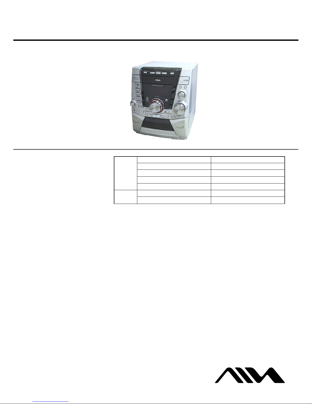
Aiwa CX-JT9 User manual

SERVICE MANUAL
COMPACT DISC DECK RECEIVER
E Model
CX-JT9
Ver 1.0 2003.05
9-877-262-01 Sony Corporation
2003E05-1 Home Audio Company
C2003.05 Published by Sony Engineering Corporation
SPECIFICATIONS
CX-JT9 is the tuner, amplifier, cassette deck and
CD player section in JAX-PK9.
Model Name Using Similar Mechanism NEW
CD CD Mechanism Type CDM74F-K6BD71A
Section Base Unit Name BU-K6BD71A
Optical Block Name KSM-213DCP
Optical Pick-up Name KSS-213D
Tape deck Model Name Using Similar Mechanism NEW
Section Tape Transport Mechanism Type CWM43RR23
TUNER
FM tuning range 87.5 MHz to 108 MHz
FM usable sensitivity (IHF) 13.2 dBf
FM antenna terminal 75 ohms (unbalanced)
AM tuning range 530 kHz to 1710 kHz (10 kHz step)
531 kHz to 1710 kHz (9 kHz step)
AM usable sensitivity 350 µV/m
AM antenna Loop antenna
AMPLIFIER
Power output Front:
Rated: 156 W + 156 W (6 ohms,
T.H.D. 1 %, 1 kHz)
Reference: 195 W + 195 W (6 ohms,
T.H.D. 10 %, 1 kHz)
Front and Surround:
320 W + 200 W (Front Speaker: 6
ohms, Surround Speaker: 8 ohms,
T.H.D. 10 %, 1 kHz/DIN AUDIO)
Total harmonic distortion 0.08 % (98 W, 1 kHz, 6 ohms, DIN
AUDIO)
Input MD (VIDEO): 1.5 V
MIC: 1 mV (600 ohms)
Outputs FRONT SPEAKER: 6 ohms or more
SURROUND SPEAKER: 8 ohms or
more
PHONES: 32 ohms or more
CASSETTE DECK
Track format 4 tracks, 2 channels stereo
Frequency response 50 Hz – 8 kHz
Recording system AC bias
Heads Deck A: playback x 1
Deck B: recording/playback x 1,
erase x 1
CD PLAYER
Laser Semiconductor laser
(λ= 780 nm)
Emission duration:
continuous
D/A converter 1 bit dual
Signal-to-noise ratio 85 dB (1 kHz, 0 dB)
Harmonic distortion 0.05 % (1 kHz, 0 dB)
GENERAL
Power requirements 120 V/220 V/230 V-240 V AC
(Switchable), 50 Hz/60 Hz
Power consumption 255 W
Power consumption With ECO mode on: 0.25 W
in standby mode With ECO mode off: 28 W
Dimensions (W x H x D) 280 x 328 x 446 mm
Weight 11.2 kg
Specifications and external appearance are subject to change
without notice.
COPYRIGHT
Check copyright laws relevant to recordings from discs, tuner
or tape for the country where the unit is to be used.
Licensed by BBE Sound, Inc. under USP4638258, 5510752
and 5736897.

CX-JT9
2
Notes on chip component replacement
•Never reuse a disconnected chip component.
•Notice that the minus side of a tantalum capacitor may be dam-
aged by heat.
Flexible Circuit Board Repairing
•Keep the temperature of the soldering iron around 270 ˚C dur-
ing repairing.
•Do not touch the soldering iron on the same conductor of the
circuit board (within 3 times).
•Be careful not to apply force on the conductor when soldering
or unsoldering.
CAUTION
Use of controls or adjustments or performance of procedures
other than those specified herein may result in hazardous ra-
diation exposure.
SAFETY-RELATED COMPONENT WARNING!!
COMPONENTS IDENTIFIED BY MARK 0OR DOTTED
LINE WITH MARK 0ON THE SCHEMATIC DIAGRAMS
AND IN THE PARTS LIST ARE CRITICAL TO SAFE
OPERATION. REPLACE THESE COMPONENTS WITH
SONY PARTS WHOSE PART NUMBERS APPEAR AS
SHOWN IN THIS MANUAL OR IN SUPPLEMENTS PUB-
LISHED BY SONY.
CLASS 1 LASER PRODUCT
LUOKAN 1 LASER LAITE
KLASS 1 LASER APPARAT
This appliance is classified
as a CLASS 1 LASER
product.
This label is located on the
rear exterior.

CX-JT9
3
TABLE OF CONTENTS
1. SERVICING NOTES ................................................ 4
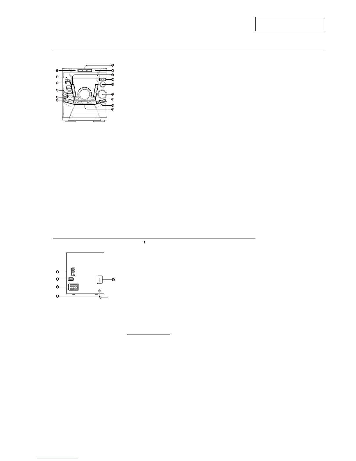
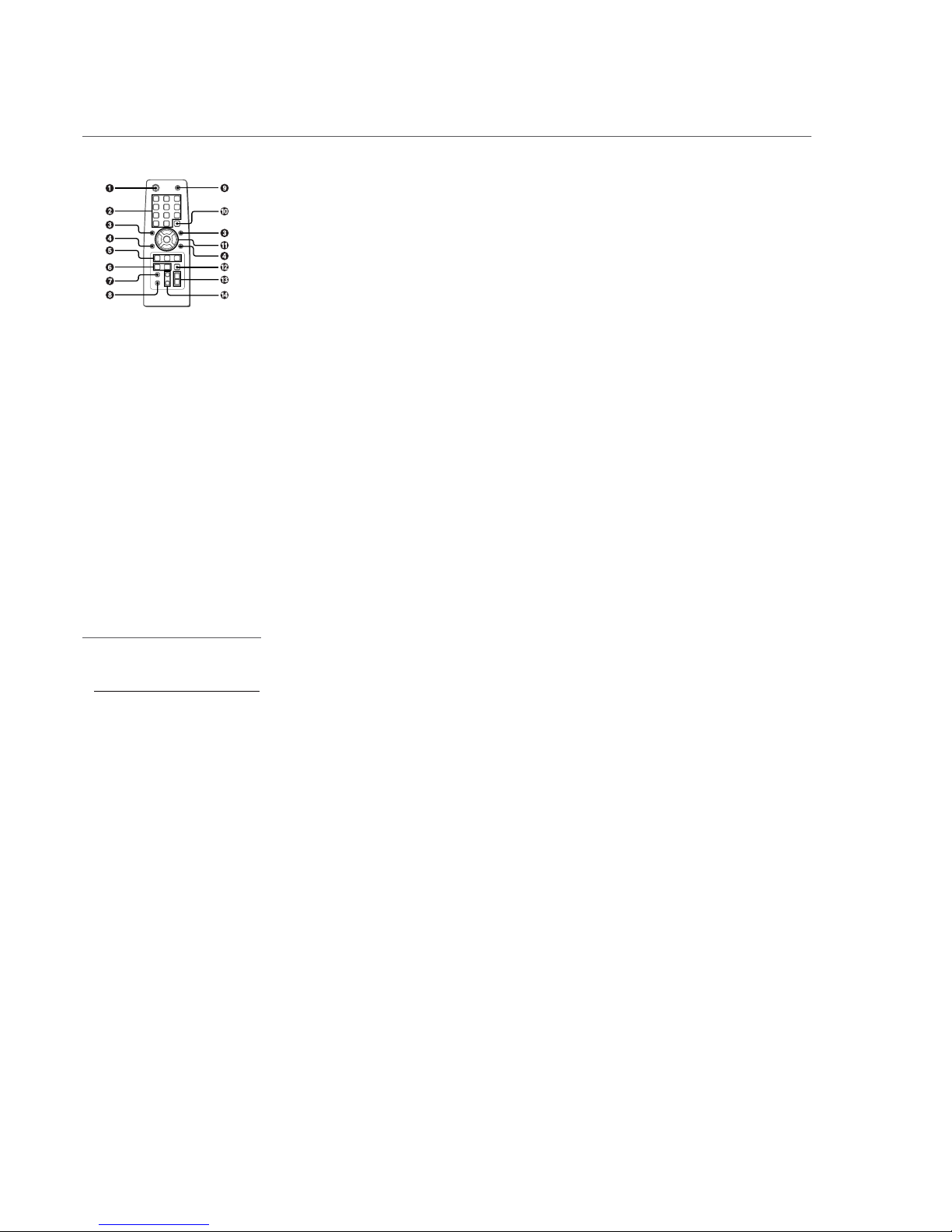
2. GENERAL
Location of Controls ....................................................... 7
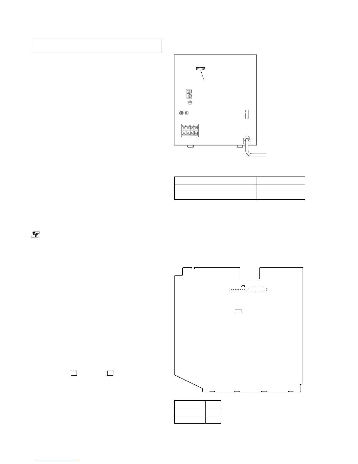
3. DISASSEMBLY
3-1. Disassembly Flow ........................................................... 9
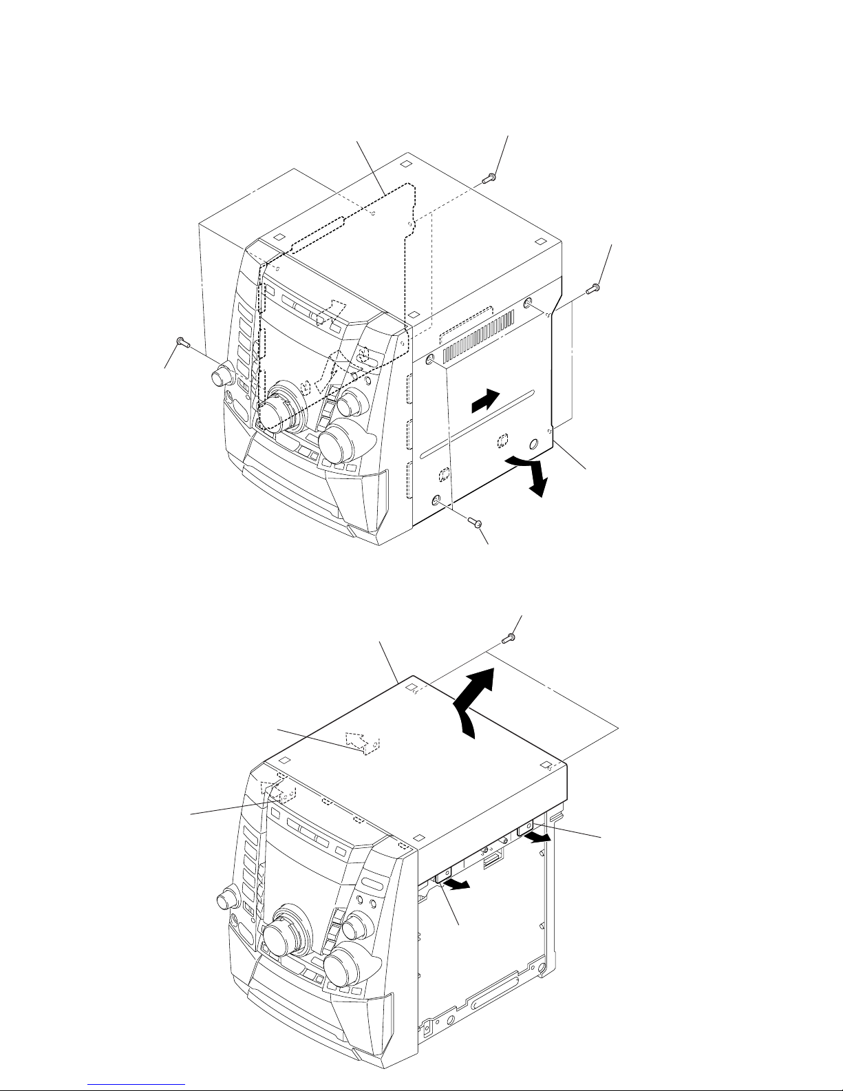
3-2. Case (SIDE-L/R)............................................................. 10
3-3. Case (Top) ....................................................................... 10
3-4. Tray Panel........................................................................ 11
3-5. CD Mechanism Deck (CDM74F-K6BD71A)................ 11
3-6. Front Panel Section ......................................................... 12
3-7. Mechanical Deck............................................................. 12
3-8. Rear Cabinet Section ...................................................... 13
3-9. Main Board...................................................................... 13
3-10. Power Board .................................................................... 14
3-11. Transformer Board .......................................................... 14
3-12 Table Assy ....................................................................... 15
3-13. Motor (TB) Board ........................................................... 15
3-14. Motor (LD) Board ........................................................... 16
3-15. Base Unit (BU-K6BD71A)............................................. 16
3-16. Motor Gear Assy (Sled) (M701), BD Board .................. 17
3-17. Optical Pick-up (KSS-213D) .......................................... 17
4. TEST MODE.............................................................. 18
5. ELECTRICAL ADJUSTMENTS
CD Section ...................................................................... 21
6. DIAGRAMS
6-1. Block Diagram – CD Section – ..................................... 22
6-2. Block Diagram – TUNER/TAPE/PANEL Section –..... 23
6-3. Block Diagram –AMP/POWER SUPPLY Section – ... 24
6-4. Note for Printed Wiring Boards and
Schematic Diagrams ....................................................... 25
6-5. Printed Wiring Board – BD Board – ............................. 26
6-6. Schematic Diagram – BD Board – ................................ 27
6-7. Printed Wiring Boards – CHANGER Section –............ 28
6-8. Schematic Diagram – CHANGER Section –................ 29
6-9. Schematic Diagram
– MAIN Board (1/4) (Suffix-11) – ................................. 30
6-10. Schematic Diagram
– MAIN Board (2/4) (Suffix-11) – ................................. 31
6-11. Schematic Diagram
– MAIN Board (3/4) (Suffix-11) – ................................. 32
6-12. Schematic Diagram
– MAIN Board (4/4) (Suffix-11) – ................................. 33
6-13. Printed Wiring Board – MAIN Board (Suffix-11) – ..... 34
6-14. Printed Wiring Board – MAIN Board (Suffix-13) – ..... 35
6-15. Schematic Diagram
– MAIN Board (1/4) (Suffix-13) – ................................. 36
6-16. Schematic Diagram
– MAIN Board (2/4) (Suffix-13) – ................................. 37
6-17. Schematic Diagram
– MAIN Board (3/4) (Suffix-13) – ................................. 38
6-18. Schematic Diagram
– MAIN Board (4/4) (Suffix-13) – ................................. 39
6-19. Printed Wiring Board – Power Board – (E51 model) ... 40
6-20. Printed Wiring Board – Power Board – (MX model) ... 41
6-21. Schematic Diagram – Power Board (1/2) –................... 42
6-22. Schematic Diagram – Power Board (2/2) –................... 43
6-23. Printed Wiring Boards – CD BUTTON/
HEADPHONE/MICROPHONE Boards – ..................... 44
6-24. Schematic Diagram – CD BUTTON/
HEADPHONE/MICROPHONE Boards – ..................... 45
6-25. Printed Wiring Board – PANEL Board – ...................... 46
6-26. Schematic Diagram – PANEL Board – ......................... 47
6-27. Printed Wiring Board – TRANSFORMER Board –
(E51 model)..................................................................... 48
6-28. Printed Wiring Board – TRANSFORMER Board –
(MX model)..................................................................... 49
6-29. Schematic Diagram – TRANSFORMER Board –
(E51 model)..................................................................... 50
6-30. Schematic Diagram – TRANSFORMER Board –
(MX model)..................................................................... 51
6-31. IC Pin Function Description ........................................... 55
7. EXPLODED VIEWS
7-1. Case Section .................................................................... 61
7-2. Front Panel Section-1...................................................... 62
7-3. Front Panel Section-2...................................................... 63
7-4. Front Panel Section-3...................................................... 64
7-5. Front Panel Section-4...................................................... 65
7-6. Chassis Section-1 ............................................................ 66
7-7. Chassis Section-2 ............................................................ 67
7-8. CD Mechanism Deck Section-1
(CDM74F-K6BD71A) .................................................... 68
7-9. CD Mechanism Deck Section-2
(CDM74F-K6BD71A) .................................................... 69
7-10. CD Mechanism Deck Section-3
(CDM74F-K6BD71A) .................................................... 70
7-11. Base Unit Section (BU-K6BD71A) ............................... 71
8. ELECTRICAL PARTS LIST ............................... 72
•Abbreviation
E51 : Chilean and Peruvian models
MX : Mexican model

4
CX-JT9 SECTION 1
SERVICING NOTES
NOTES ON HANDLING THE OPTICAL PICK-UP
BLOCK OR BASE UNIT
The laser diode in the optical pick-up block may suffer electro-
static break-down because of the potential difference generated
by the charged electrostatic load, etc. on clothing and the human
body.
During repair, pay attention to electrostatic break-down and also
use the procedure in the printed matter which is included in the
repair parts.
The flexible board is easily damaged and should be handled with
care.
NOTES ON LASER DIODE EMISSION CHECK
The laser beam on this model is concentrated so as to be focused
on the disc reflective surface by the objective lens in the optical
pick-up block. Therefore, when checking the laser diode emis-
sion, observe from more than 30 cm away from the objective lens.
LASER DIODE AND FOCUS SEARCH OPERATION
CHECK
Carry out the “S curve check” in “CD section adjustment” and
check that the S curve waveforms is output three times.
•MODEL IDENTIFICATION
– Back Panel –
MODEL PART No.
Chilean and Peruvian models 4-245-109-0[]
Mexican model 4-245-109-2[]
PART No.
UNLEADED SOLDER
Boards requiring use of unleaded solder are printed with the lead-
free mark (LF) indicating the solder contains no lead.
(Caution: Some printed circuit boards may not come printed with
the lead free mark due to their particular size)
: LEAD FREE MARK
Unleaded solder has the following characteristics.
•Unleaded solder melts at a temperature about 40 ˚C higher than
ordinary solder.
Ordinary soldering irons can be used but the iron tip has to be
applied to the solder joint for a slightly longer time.
Soldering irons using a temperature regulator should be set to
about 350 ˚C.
Caution: The printed pattern (copper foil) may peel away if the
heated tip is applied for too long, so be careful!
•Strong viscosity
Unleaded solder is more viscou-s (sticky, less prone to flow)
than ordinary solder so use caution not to let solder bridges oc-
cur such as on IC pins, etc.
•Usable with ordinary solder
It is best to use only unleaded solder but unleaded solder may
also be added to ordinary solder.
D324
CN309
IC303
CN312
– MAIN BOARD (Conductor Side) –
•DISCRIMINATION
Either type of the MAIN board, Part No. 1-688-080-11 or 1-688-
080-13 is used for Chilean and Peruvian models.
Note: For Mexican model, only one type of the MAIN board, Part No. 1-
688-080-13 is used.
How to identify the type is described below.
D324
Suffix-11 ×
Suffix-13 a
RELEASING THE DISC TRAY LOCK
The disc tray lock function for the antitheft of an demonstration
disc in the store is equipped.
Releasing Procedure :
While pressing the xkey, press the Zkey for 5 seconds. The
message “UNLOCKED” is displayed and the tray is unlocked.
Note: When “LOCKED” is displayed, the tray lock is not released by
turning power on/off with the [POWER] key.

5
CX-JT9
HOW TO OPEN THE DISC TRAY WHEN POWER SWITCH TURNS OFF.
2
Turn the loading gear
in the direction of arrow
A
.
1
Remove the case (side-L).
A
3
Pull-out the disc tray.

6
CX-JT9
SERVICE POSITION
– CD mechanism deck –
–Tape mechanism deck –
main board (CN312)
Connect wire (flat type) (19 core) to
main board (CN312) and BD board (CN710).
BD board (CN710)
Connect wire (flat type) (13 core) to
panel board (CN601) and mechanical deck.
panel board (CN601)
main board (CN203)

7
CX-JT9
SECTION 2
GENERAL This section is extracted from
instruction manual.
•LOCATION OF CONTROLS
1DISC CHANGE/DISC SKIP
Rotates the CD trays.
2POWER 6STANDBY/ON
Switches the unit on and off (standby).
The red indicator flashes when receiving a signal from
the remote.
3TAPE A/B
Selects Tape function, and deck A or B.
TUNER BAND
Selects Tuner function and the radio band.
MD (VIDEO)
Selectsthe function ofexternal equipmentconnected to
MD (VIDEO) jacks.
CD
Selects CD function.
4TREBLE/MIDDLE
Enhances high or middle frequency sound.
5CD SYNC
Starts Automatic CD dubbing.
REC PAUSE/START
Starts recording.
6PHONES jack
Plug in here an optional headphones set with a mini
stereo plug (ø3.5 mm). Speaker output is canceled.
MIC jack
Connects the microphone here.
MIC MIXING
Adjusts the microphone volume.
Main unit: front
Refer to the pages indicated in parentheses for details.
7DISC DIRECT PLAY 1-3
Selects a disc.
8zOPEN/CLOSE
Opens or closes the disc compartment.
9HEAVY, VOCAL, SALSA, TECHNO,
HIP HOP, MANUAL
Activates a graphic equalization curve.
0MODE
Selectsvariousmodes(PlaymodeandTapereverse,etc.)
whenusedin combinationwithENTERand MULTIJOG.
ENTER
Fixes the modes and the time (Play mode and Tape
reverse,etc.)whenusedincombination withMODE and
MULTI JOG.
!MULTI JOG
CD: skips to a previous or a succeeding track.
Tuner: selects a preset station.
Clock and Timer: sets the time.
Selectsthemodeandthetimewhenusedincombination
with MODE and ENTER.
@VOLUME
Adjusts the volume.
#BASS
Adjusts low frequency sound.
SURROUND
Switches surround on and off.
i-Bass
Produces rich and clear low frequency sound.
$DISPLAY
Displays the time and the remaining time for CD.
When the unit is off, press DISPLAY to switch between
DEMO, Clock and ECO display modes.
ALBUM k/i
Selects a previous album or a succeeding album with
MP3-CDs.
%rTUNING DOWN, tTUNING UP
(f,g)
CD: searches a track in fast forward or fast reverse
playback when held down.
Tape: fast forwards or rewinds the tape.
Tuner: manually tunes down or up within the band.
aPAUSE
CD and Tapes: pauses playback.
dDIRECTION
CD and Tapes: starts playback.
sSTOP
CD and Tapes: stops playback.
Main unit: rear
Refer to the pages indicated in parentheses for details.
1AM LOOP, FM 75 Ωterminals
Plug in the supplied AM and FM antennas here.
2MD (VIDEO) jacks
Acceptsanalog soundsignals fromexternal equipment.
Connect using an optional connecting cable with RCA
phono plugs (red plug to R jack, white plug to L jack).
Referalsototheoperatinginstructionsofyourequipment.
To switchfunction to external input,press MD (VIDEO).
Tip:
To changethe displayedname forthis function,turn the
uniton, thenholddown MD(VIDEO)and pressPOWER
on the unit. Repeat the procedure to select “MD” or
“VIDEO”.
3SURROUND SPEAKER terminals
Connectforeachspeakerthebluecordtothe0terminal
and the black cord to the 9terminal.
FRONT SPEAKER terminals
Connectforeachspeakertheredcordtothe0terminal
and the black cord to the 9terminal.
4AC power cord
5AC VOLTAGE selector
SwitchesACvoltageamong120V,220V,and230V-240V.
Make sure it matches your local voltage.

8
CX-JT9
Buttons with the same or similar names with the main unit
basically have the same function.
1POWER
21-0/10, +10
Selects a CD track of the specified number.
The numbered buttons take on these functions below when pressed
together with SHIFT held down
:
EDIT
Enters Automatic CD dubbing mode when pressed in
stop mode.
BAND
Selects Tuner function and the radio band.
TAPE A/B
Selects Tape function, and deck A or B.
SPECTRUM
Changes the spectrum analyzer display.
TUNER MODE
Switches between stereo or monaural FM reception.
KARAOKE
Selects Vocal Fader mode.
GEQ
Enters Graphic Equalizer setting mode.
TUNER MEMORY
Tuner: stores the received station in to preset.
SURROUND
Switches surround on and off.
3r,t
CD: selects a track.
Tuner: selects a preset station.
BASS, MID and TREBLE: adjusts the level.
Clock and Timer: sets the time.
4ALBUM M/N
Selects a previous album or a succeeding album.
5PLAY MODE
CD: selects a playback mode.
Tape: selects a reverse mode
REPEAT
Enters CD repeat playback mode.
ENTER
6CLOCK/TIMER/SET
Enters timer setting mode.
CLOCK/TIMER/SELECT (24, 25)
Selects timer playback, timer recording or timer off.
7DISPLAY
Displays the time and the remaining time for CD.
When the unit is off, press DISPLAY to switch between
DEMO, Clock and ECO display modes.
8SHIFT
Holddownwhen pressinganumberedbutton to change
its function to that printed above the number.
e.g.)
“Press SHIFT+BAND on the remote” indicates “Hold
downSHIFTandpress‘2’ (BAND)”.Doingsomakesyou
be able to select Tuner function and the radio band.
Remote control
Refer to the pages indicated in parentheses for details.
9FUNCTION
Switches the active function among CD, TAPE, TUNER
and MD (VIDEO).
0DISC SKIP
Select a disc.
!c/d
CD and Tape: starts playback.
s
CD and Tape: stops playback.
f,g
CD: searches a track in fast forward or fast reverse
playback when held down.
Tape: fast forwards or rewinds the tape.
Tuner: manually tunes down or up within the band.
a
CD and Tape: pauses playback.
@SLEEP
Switchesthesleep-timeron/offand selectstheduration.
#VOLUME (+,-)
Adjusts the volume.
$SOUND
Selects BASS, MID or TREBLE setting mode
CLEAR
Clears a track of the CD programed playback.
Setting the clock
Use the remote.
1
Press CLOCK/TIMER/SET.
Go to step3 when the time appears and the ‘hour’ flashes.
2
Press ror trepeatedly until “CLOCK ”
appears in the display and then press ENTER.
3
Press ror trepeatedly to set the hour
and then press ENTER.
4
Press ror trepeatedly to set the minute
and then press ENTER.
Thetime display stops flashing and the clock starts from
00 seconds.
•MULTI JOG is also available in place of r
or t.
To d i splay the time
Press DISPLAY .The time will be displayed for 6 seconds.
Tip:
“AM 12:00” indicates midnight and “ PM
12:00” noon.
If “- -:- -” appears when the unit is turned off
There has been a power interruption. Re-set the clock.

CX-JT9
9
• This set can be disassembled in the order shown below.
3-1. DISASSEMBLY FLOW
SECTION 3
DISASSEMBLY
Set
3-2. CASE
(SIDE-L/R)
(Page 10)
3-3. CASE (TOP)
(Page 10) 3-4. TRAY PANEL
(Page 11)
3-6. FRONT PANEL
SECTION
(Page 12)
3-8. REAR CABINET
SECTION
(Page 13)
3-7. MECHANICAL
DECK
(Page 12)
3-9. MAIN BOARD
(Page 13)
3-10. POWER
BOARD
(Page 14)
3-11. TRANSFORMER BOARD
(Page 14)
3-16. MOTOR GEAR ASSY (SLED) (M701),
BD BOARD
(Page 17)
3-17. OPTICAL PICK-UP
(KSS-213D)
(Page 17)
3-15. BASE UNIT
(BU-K6BD71A)
(Page 16)
3-12. TABLE ASSY
(Page 15)
3-13. MOTOR (TB)
BOARD
(Page 15)
3-14. MOTOR (LD)
BOARD
(Page 16)
3-5. CD MECHANISM DECK
(CDM74F-K6BD71A)
(Page 11)
Note 1: The process described in can be performed in any order.
Note 2: Without completing the process described in , the next process can not be performed.

CX-JT9
10
1
two screws
(BVTP3
×
10)
7
case (top)
5
claw
3
claw
4
claw
6
2
claw
1
two screws
(BVTP3
×
10)
6
two screws
(BVTP3
×
10)
2
three screws
(case3 TP2)
5
case (side-R)
7
three screws
(case3 TP2)
3
8
9
4
0
case (side-L)
3-3. CASE (TOP)
Note: Follow the disassembly procedure in the numerical order given.
3-2. CASE (SIDE-L/R)

CX-JT9
11
3-4. TRAY PANEL
3-5. CD MECHANISM DECK (CDM74F-K6BD71A)
1
Turn the loading gear
in the direction of arrow
A
.
A
4
tray panel
3
four claws
2
Pull-out the disc table.
3
screw (BVTP3
×
10)
4
screw (BVTP3
×
10)
5
two screws
(BVTP3
×
10)
1
wire (flat type) (19 core)
(CN312)
6
CD mechanism deck
(CDM74F-K6BD71A)
2
connector (CN701)

CX-JT9
12
3-6. FRONT PANEL SECTION
3-7. MECHANICAL DECK
2
connector (CN310)
4
connector (CN203)
3
connector (CN202)
5
wire (flat type) (9 core)
(CN311)
7
front panel section
6
three screws
(BVTP3
×
10)
1
wire (flat type) (31 core)
(CN304)
3
mechanical deck
1
wire (flat type) (13core)
2
six screws
(BVTP3
×
10
)
4
ground mechanical plate

CX-JT9
13
6
rear cabinet section
5
five screws
(BVTP3
×
10)
2
connector (CN303)
1
wire (flat type) (11core)
4
cover (duct)
3
two screws
(BVTP3
×
10)
3-8. REAR CABINET SECTION
3-9. MAIN BOARD
1
two screws
(BVTP3
×
10)
3
main board
2
two connectors
(CN306, CN307)

CX-JT9
14
3-10. POWER BOARD
3-11. TRANSFORMER BOARD
4
power board
2
two screws
(BVIT3B+3-8R)
3
two screws
(BVIT3B+3-8R)
1
connector (CN902)
3
trans holder
2
screw
(BVTT3
×
8)
5
four screws
(ITC+4-10R)
1
screw
(BVTP3
×
10)
6
transformer board
4

CX-JT9
15
3-12. TABLE ASSY
3
wire (flat type) (5 core
)
(CN702)
4
hook
1
Turn the loading gear
in the direction of arrow
A
.
A
5
two claws
2
Pull-out the table assy.
6
table assy
3-13. MOTOR (TB) BOARD
2
table (loading)
4
connector
(CN731)
1
screw
(PTPWH M2.6)
5
two screws
(BTTP M2.6)
6
motor (TB) boar
d
3
belt (table)

CX-JT9
16
3-14. MOTOR (LD) BOARD
3-15. BASE UNIT (BU-K6BD71A)
2
connector
(CN704)
3
two screws
(BTTP M2.6)
4
motor (LD) board
1
belt (loading)
3
four coil springs
(insulator)
4
four insulators
1
four screws
(BTTP M2.6)
2
four stoppers (BU)
5
base unit
(BU-K6BD71A)

CX-JT9
17
1
Remove two
solders.
qa
BD board
2
two screws
(P2
×
3)
6
claw
7
gear (A)
8
gear (B)
5
wire (flat type) (16 core
)
(CN708)
0
motor gear assy (SLED)
(M701)
3
screw (P2.6
×
6)
9
Remove two solders.
4
2
sled shaft
1
Slide the lever
in the direction of arrow
A
.
3
Remove the optical pick-up
(KSS-213D) in the direction
of arrow
B
.
A
B
3-16. MOTOR GEAR ASSY (SLED) (M701), BD BOARD
3-17. OPTICAL PICK-UP (KSS-213D)

18
CX-JT9 SECTION 4
TEST MODE
[COLD RESET]
•The cold reset clears all data including preset data stored in the
RAM to initial conditions. Execute this mode when returning
the set to the customer.
Procedure:
1. Press the [POWER] key to turn the power ON.
2. Pressthree keysof x, [ENTER] and[POWER] simultaneously.
3. The message “RESET” is displayed on the fluorescent indicator
tube momentarily, then becomes standby states.
[TUNER STEP CHANGE-OVER]
•Astep ofAM channels can be changed over between 9 kHz and
10 kHz.
Procedure:
1. Press the [POWER] key to turn the power ON.
2. Press the [TUNER BAND] key to select “AM”.
3. Press the [POWER] key to turn the power OFF.
4. Press two keys of [ENTER] and [POWER] simultaneously.
5. The message “9K STEP” or “10K STEP” is displayed on the
fluorescent indicator tube, and thus the channel step is changed
over.
[CD SHIP MODE]
•This mode moves the optical pick-up to the position durable to
vibration. Use this mode when returning the set to the customer
after repair.
Procedure:
1. Press the [POWER] key to turn the power ON.
2. Press the [CD] key to select “CD”.
3. Press two keys of [CD] and [POWER] simultaneously.
4. The message “LOCK” is displayed on the fluorescent indicator
tube, and the CD ship mode is set.
[CHANGE-OVER FUNCTION OF MD/VIDEO]
•This mode is used to enable function of external input to change
over between MD and VIDEO.
Procedure:
1. Set to standby state.
2. Presstwo keysof[MD VIDEO ] and[POWER] simultaneously.
3. The message “MD” or “VIDEO”is displayed on the
fluorescent indicator tube, and the function of external input
is changed over.
[CDTRAY LOCK MODE]
•This mode is used to unable to take sample disc out of tray in
the shop.
Procedure:
1. Press the [POWER] key to turn the power ON.
2. Press the [CD] key to select “CD”.
3. While pressing the xkey, press the Zkey for 5 seconds.
4. The message “LOCKED” is displayed on the fluorescent
indicator tube and the tray is locked. (Even if pressing
the Zkey, the message “LOCKED” is displayed on the
fluorescent indicator tube and the tray is locked)
5. To release from this mode, while pressing the xkey, press
the Zkey for 5 seconds.
6. The message “UNLOCKED” is displayed on the fluorescent
indicator tube and the tray is unlocked.
[AMPTEST MODE]
•This mode is used to set the parameter ofAMP IC and EQ band
level and i-bass IC.
Procedure:
1. Press the [POWER] key to turn the power ON.
2. Pressthreekeysof x,[HIP HOP] and [HEAVY] simultaneously.
3. When the AMP test mode is activated, the message “AMP
TEST” is displayed on the fluorescent indicator tube
momentarily.
4. Press two keys of [HEAVY] and [DISC DIRECT PLAY 2]
simultaneously, mode is changed over to parameter setting
of AMP IC and EQ band level and i-bass IC.
5. In theAMP IC setting mode, press the [ENTER] key, surround
ON/OFF is changed over.
6. In the EQ band level setting mode, press the [MANUAL] key,
EQ band is changed over to LOW, MID or HIGH.
7. In the i-bass IC setting mode, turn the [BASS] knob, up/down
i-bass level, press the [i-BASS] key, i-bass f0level is change
over between 1 to 3.
8. To release from this mode, press two keys of [HEAVY] and
[TECHNO] simultaneously.
)(

19
CX-JT9
[AGING MODE]
•This mode can be used for operation check of CD section and
tape deck section.
CD section and tape deck section work in parallel.
If an error occurred:
The aging operation stops only an error occurred sections and
display then status.
If no error occurs:
The aging operation continues repeatedly.
Procedure:
1. Press the [POWER] key to turn the power ON.
2. Press the [CD] key to select “CD”.
3. Set disc on the tray and set tape into the deck.
4. Set the “ALL DISCS” mode and “REV OFF” mode.
5. Pressthreekeysof x,[HEAVY] and[DISC CHANGE/DISC SKIP]
simultaneously.
6. Themessage “AGING” is displayed on the fluorescent indicator
tube momentarily, then aging operations of CD and tape are
started at the same time.
7. To release from this mode, operate the “COLD RESET”.
1. Display at the Aging Mode
Display operating state of CD section and tape deck section
alternately.
If an error occurred, stop display which that section.
2. CD Section
The sequence during the aging mode is following as below.
Display at the aging mode is the same as the normal operation.
Aging mode sequence (CD section) :
Start (from disc 1)
Disc chucking
TOC read
Play first track for 2 seconds
Play last track for 2 seconds
EX-change open/close
Open the disc tray
Disc skip
Close the tray
Change the next disc.
3. Tape Deck Section
The sequence during the aging mode is following as below.
If an error occurred, stop display that step.
Aging mode sequence (tape deck section) :
Rewind the tape A and B
“AAG-1 or 2”
Shut off
FWD play the tape A
“AAG-3”
2 minutes
Fast forward the tape A
“AAG-4”
Shut off or 20 seconds
REV play the tape A
“AAG-5”
2 minutes
Rewind the tape A
“AAG-6”
Shut off
FWD play the tape B
“BAG-3”
2 minutes
Fast forward the tape B
“BAG-4”
Shut off or 20 seconds
REV play the tape B
“BAG-5”
2 minutes
Rewind the tape B
“BAG-6”
Shut off
Note: “*AG-*” is display of each step.

20
CX-JT9
[GCTEST MODE]
•This mode is used to check the fluorescent indicator tube, LED
and key.
Procedure:
1. Press the [POWER] key to turn the power ON.
2. Press three keys of x, [HEAVY] and [DISC DIRECT PLAY 2]
simultaneously.
3. Fluorescent indicator tube and LEDs are all turned ON.
4. Press two keys of [HEAVY] and [DISC DIRECT PLAY 2]
simultaneously, mode is changed over.
5. In the key check mode, press each key, the defined key number
of every each key list is displayed on the fluorescent indicator
tube.
6. In the key count check mode, “K-CNT 0” is displayed on the
fluorescent indicator tube. Each time a key is pressed, “K”
value increases. However, once a key is pressed, it is no longer
taken into account.
7. In the headphone input check mode, connect the headphone,
the message “H_P ON” is displayed on the fluorescent indicator
tube, and disconnect the headphone, the message “H_P OFF”
is displayed on the fluorescent indicator tube.
8. In the volume check mode, turn the [VOLUME] knob, the
display on the fluorescent indicator tube is changed over to
“VOL UP”, “VOL FLAT” or “VOL DOWN”
[MCTEST MODE]
•This mode is used to check operations of Amplifier.
Procedure:
1. Press the [POWER] key to turn the power ON.
2. Press three keys of x, [HEAVY] and [DISC DIRECT PLAY 3]
simultaneously.
3. When the MC test mode is activated, the message “MC MODE”
is displayed on the fluorescent indicator tube momentarily, then
VACS level is displayed on the fluorescent indicator tube.
4. Press the [TECHNO] key, the display on the fluorescent
indicator tube is changed over to “EQ MAX”, press the
[MANUAL] key, the display on the fluorescent indicator tube
is changed over to “EQ MID”, press the [HIP HOP] key,
the display on the fluorescent indicator tube is changed over
to “EQ MIN”,
5. Turn the [VOLUME] knob, the display on the fluorescent
indicator tube is changed over to “VOL MAX”, “VOL MID”
or “VOL MIN”
6. When the [REC PAUSE/START] key is pressed with a tape
set in the deck-B, the function is switched “MD” or “VIDEO”
and recording starts. When the mor Mkey is pressed
during recording, the tape is rewound back to the beginning of
recording, the function is switched to “TAPE B”, then playback
starts.
7. When the [CD SYNC] key is pressed with the test tape (AMS-
100,AMS-110A) in the deck, number of space between tunes
is counted, then ifAMS-110A is set, “OK” is displayed on the
fluorescent indicator tube and if AMS-100 is set, “NG” is
displayed on the fluorescent indicator tube.
8. To release from this mode, press the [POWER] key.
[MODEL, DESTINATION AND VERSION DISPLAY]
•This mode is used to check the model, destination and software
version.
Procedure:
1. Set to the standby state.
2. Pressthree keysof x,[TECHNO] and[HEAVY] simultaneously.
3. When the model, destination and version display mode is
activated, the model an destination is displayed on the
fluorescent indicator tube.
4. Press two keys of [HEAVY] and [DISC DIRECT PLAY 2]
simultaneously,mode is changed over to modeland destination
display mode and version display mode.
5. In the version display mode, press the [DISC DIRECT PLAY 3]
key, display is changed over to version display and year, month
and day of the software creation display.
6. To release from this mode, press the two keys of [TECHNO]
and [HEAVY] simultaneously.
[CD SERVICE MODE]
•This mode can run the CD sled motor freely. Use this mode, for
instance, when cleaning the optical pick-up.
Procedure:
1. Press the [POWER] key to turn the power ON.
2. Press the [CD] key to select “CD”.
3. Press three keys of x, [HEAVY] and Zsimultaneously.
4. When the CD service mode is activated, the message “TRVS
ON” is displayed on the fluorescent indicator tube.
5. Press the Mkey, optical pick-up move to outside track and
the message “SLED OUT” is displayed on the fluorescent
indicator tube.
6. Press the mkey, optical pick-up move to inside track and
the message “SLED IN” is displayed on the fluorescent
indicator tube..
7. Press the [TECHNO] key, traverse ON/OFF is changed over.
[5 REPEAT LIMIT CANCEL]
•Number of repeat for CD playback is 5 times when the repeat
mode is “REPEAT”. This mode is used to enables CD to repeat
playback for limitless times.
Procedure:
1. Press the [POWER] key to turn the power ON.
2. Press the [CD] key to select “CD”.
3. Press three keys of x, [HEAVY] and Ysimultaneously.
Table of contents
Other Aiwa Stereo System manuals