Akai ACR-49MP User manual

SERVICE MANUAL
Model:
ACR-49MP
CD/MP3–RECIVER
www.akai.ru

2
CONTENTS
Page
Disassembly Instructions.......................................................................................................................................3
Disassembly Diagram............................................................................................................................................4
Operation Check....................................................................................................................................................5
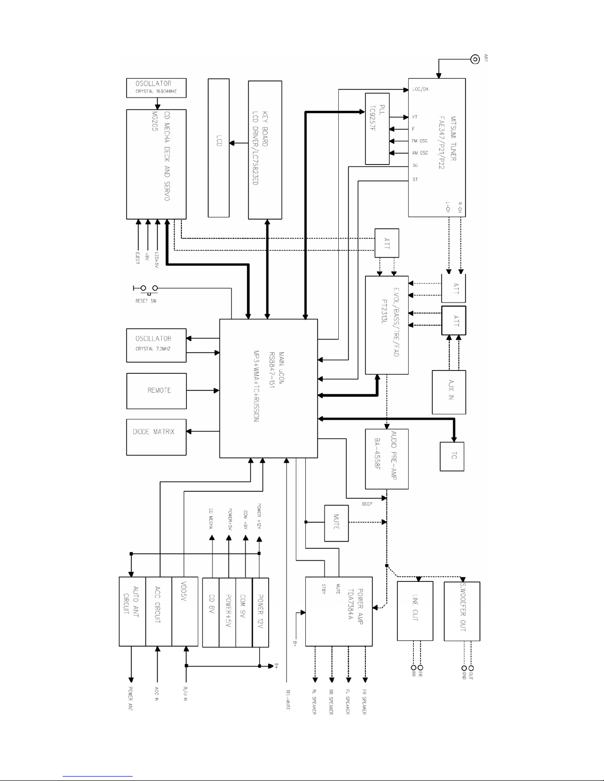
Block Diagram .......................................................................................................................................................6
Alignment Locations ..............................................................................................................................................7
Alignment Procedures ...........................................................................................................................................8
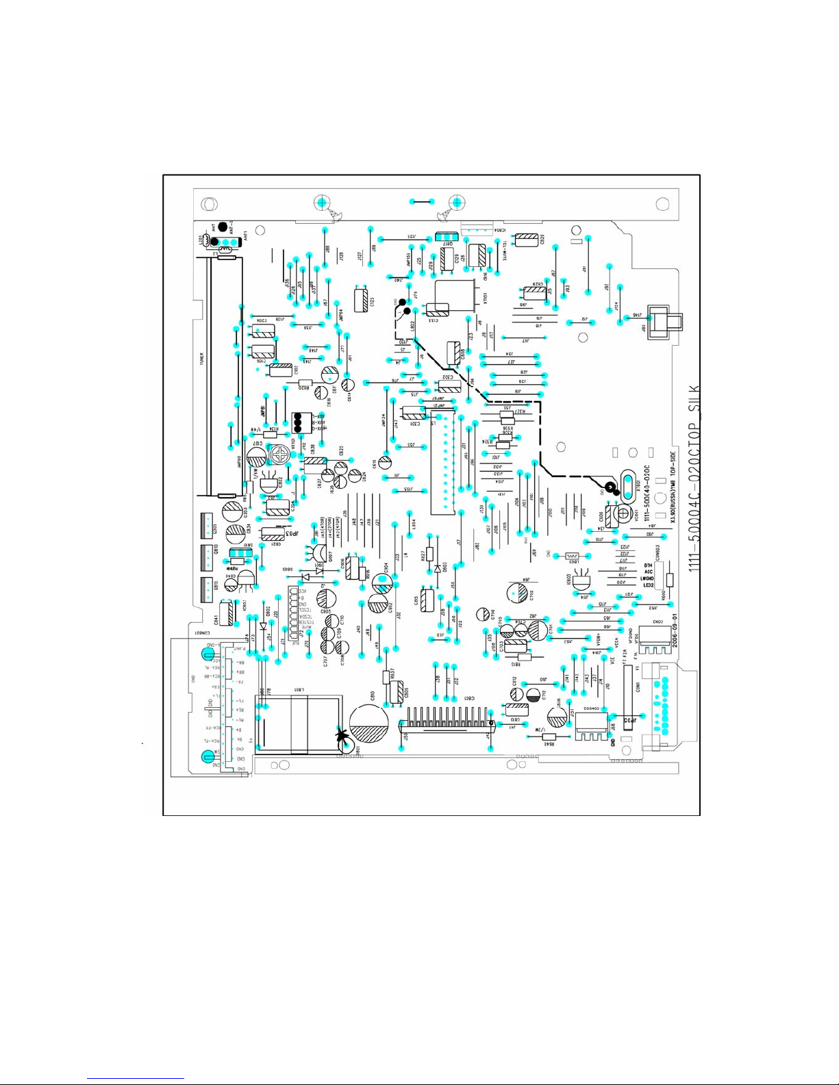
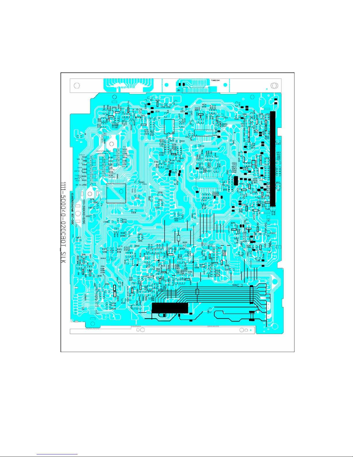
Printed Circuit Boards............................................................................................................................................9
Exploded Views (Panel).......................................................................................................................................15
Exploded View Parts Lists (Panel) ......................................................................................................................16
Exploded Views (Cabinet) ...................................................................................................................................17
Exploded View Parts Lists (Cabinet)...................................................................................................................18
Exploded Views (Deck)........................................................................................................................................19
Exploded View Parts Lists (Deck) .......................................................................................................................20
Schematic Diagram .............................................................................................................................................22
Electrical Parts List ..............................................................................................................................................25
Specifications.......................................................................................................................................................31

3
DISASSEMBLY INSTRUCTIONS
1. Using the unlock key that came with the unit or a similar tool, unlock the Mounting Box and remove toward
the rear of the unit.
2. Remove two screws (A) located on the rear of the top cabinet then remove the Top Cabinet.
3. Remove two screws (B) located on the rear of the bottom cabinet then remove the Bottom Cabinet.
4. Take out the Front Panel and the Ring.
Remove two screws (C) from on the front side of the Base.
5. Remove two screws (D) from on the right side of the Rear-right Cabinet.
Remove the screw (E) from on the left side of the Rear-right Cabinet and the screw (F) on the right side of
the heat sink.
6. Remove two screws (G) from under the deck front bracket then remove the Deck Front Bracket.
Remove two screws (H) from under the deck rear bracket then remove the Deck Rear Bracket and the Deck.
7. Remove two screws (I) from on the left side of the heat sink.
8. Remove two screws (J) from on the left side of the heat sink then remove the IC Bracket.
9. Remove two screws (K) from on the rear side of Rear-right Cabinet then remove the Power IC Bracket.
10. Remove the screw (L) from on the back of the side bracket then remove Wire Clip.
11. Remove two screws (M) from each side of the base then remove the Base.
12. Remove three screws (P) from under the main board then remove the Heat Sink, Rear-right Cabinet and the
Main Board.

4
DISASSEMBLY DIAGRAM

5
OPERATION CHECK
GENERAL SPECIFICATIONS OF SIGNAL
Standard frequency
Signal output
Modulation
FM
MW
FM
MW
MW
FM Stereo
98.1 MHz (65.0, 74.0MHz) (87.5, 107.9 MHz)
1000 kHz (530, 1710 kHz)
1mV
5 mV
400 Hz 30% MOD.
1 kHz 75kHz DEV.
46% for L only or
Ronlypilotlevel8%
AF output level FM/MW
Power source voltage DC 14.0V (Backup voltage is the same as this)
AF load impedance 4 ohm pure resistance
Balance Center position of level
Tone Center position
The signal strength read in this section is voltage on the antenna.
TestDiagram
4-SPEAKER
VTVM
DISTORTION
METER
2-SPEAKER
FRONT
SPK.
SPK.
FL.
RL.
SPR.
MAIN UNIT
AM SG
VTVM ANTANNA
DUMMY
FM SG
MODULATOR
STEREOS
MPX
ANT
FRONT
SPK.
SPE.
FR.
RR.
4-SPEAKER
SPK.
2-SPEAKER
POWER ANTANNA
ACC (DV14.4V)
GROUND
BACK UP (14.4V)

6
BLOCK DIAGRAM

7
ALIGNMENT LOCATIONS
MITSUMI BOARD

8
ALIGNMENT PROCEDURES
FM ADJUSTMENT
Equipment Required
zAM IF/RF signal generator
zSolid-state voltmeter (SSVM)
zRegulated DC power supply
z2-CH voltmeter
zDistortion meter
FM Alignment Using FM Signal Generator
Note: Press the radio power switch to on the radio. Signal generator output must be kept as low as possible
to avoid overload and clipping.
Step Generator
Coupling Generator Display
Setting Adjustment Remarks
Stereo
Separation Signal
Generator
to antenna
receptacle
98.1 MHz
Int. 1 kHz
Dev. 75 kHz
L+R = 90 %
Pilot = 10 %
98.1 MHz
VR1 Adjust AF
output power
at maximum
separating
more than 30 dB
FM SNC
Adjustment 98.1 MHz
Dev. 75 kHz
L+R=90 %
Int. 1 kHz
60dBµV output
98.1 MHz
@ 40 dBµ
98.1 MHz
VR2
Stereo Separation
25 dB (±5 dB)
Stop
SENS. Signal Generator
to antenna
receptacle
98.1 MHz
Mod. 1kHz
Dev 75kHz
98.1 MHz VR3 Adjust AF to
stop station.
Note: The tuner module is well-adjust and adjustment is not recommended.

9
PRINTED CIRCUIT BOARDS
MAIN BOARD
TOP VIEW

10
MAIN BOARD
BOTTOM VIEW

11
KEY BOARD
TOP VIEW

12
KEY BOARD
BOTTOM VIEW

13
CD SERVO BOARD
TOP VIEW

14
CD SERVO BOARD
BOTTOM VIEW

15
EXPLODED VIEW
PANEL

16
EXPLODED VIEW PARTS LIST
PANEL
Ref. No. Description RS Part No. Mfr’s Part No.
1
2
3
4
5
6
7
8
9
10
11
12
13
14
15
16
17
18
19
20
21
22
23
24
25
26
27
28
29
30
31
32
33
34
35
36
37
38
Lens(S.N0000/WHT)DX3.82.25N/SW/IR(AKAI ACR-49MP)
ROHS
T. Panel (S. N1204) X3.18.9 ROHS
Panel Bottom ROHS
Decorate B (S. N1204) ROHS
Left Decorate A (S. N1204) ROHS
N/USB Decorate D (S. N1204) ROHS
Release (S. N1204) ROHS
“Open” Spring ROHS
SEL Base (S. N1204) ROHS
Decorate For Volume (Crystal/Red) ROHS
SEL Knob (L-Up) (S. N1204) ROHS
SEL Knob-A (Crystal/Red) ROHS
Stopper For SEL ROHS
EQ (L-Up) (S. N1204) ROHS
Adaptor For EQ ROHS
Power (Crystal/Red Warm Red C) ROHS
Adaptor For PWR ROHS
AS/PS/2SCN/4SHF/6 (L-Up) (S. N1204) ROHS
1PAU/3RPT/5 (L-Up) (S. N1204) ROHS
MD (L-Up) (S. N1204) ROHS
MD Knob (Crystal/Red) ROHS
TUN/TRK (L-Up) (S. N1204) ROHS
BND (Crystal/Red Warm Red C) ROHS
Adaptor For BND ROHS
EJ (L-Up) (S.N1204) ROHS
Decorated Ring (S. N1204) ROHS
LOC/MON/DSP/MUT (L-UP) (S.N1204) ROHS
4D Knob (Clear/Red) ROHS
Adaptor For 4D ROHS
B-L For 4D ROHS
B-L For CD-Mouth ROHS
B-L For Main Key ROHS
Key Board
LCD Bracket Real (E) ROHS
CD3001 LCD TN NEG COLOR Black Mask 22X84 PIN
ROHS
CD1007 B. Light /White ROHS
Screw Ø2X8 BA/ST Black ROHS
AKAI Logo (S. N0000) Silver Hot Stamp ROHS
5300-0J2060-357
5100-0J2021-82Y
5100-0C2522-00
5200-0J2039-80
5200-0J2038-80
5200-0J2041-80
5200-0J2035-80
3600-040205-00
5200-0J2037-80
5200-0J2058-50
5200-0J2029-81
5200-0J2057-50
5200-0J2056-00
5200-0J2022-81
5200-0J2053-00
5200-0J2051-51S
5200-0J2033-00
5200-0J2025-82
5200-0J2026-82
5200-0J2030-81
5200-0J2052-50
5200-0J2024-81
5200-0J2051-52S
5200-0J2032-00
5200-0J2021-81
5200-0J2036-80
5200-0J2027-82
5200-0J2054-50
5200-0J2034-00
5200-0J2055-00
5200-0J2023-00
5200-0J2062-00
1121-300630-3108
3900-0E2004-00
2700-300200-110Y
0200-001007-09
4000-012008-21
5200-0G6340-31

17
EXPLODED VIEW
CABINET

18
EXPLODED VIEW PARTS LIST
CABINET
Ref. No. Description RS Part No. Mfr’s Part No.
1
2
3
4
5
6
7
8
9
10
11
12
13
14
15
16
17
18
19
20
21
22
23
24
25
26
27
28
29
30
31
32
33
Panel
Ring (S.N1204) ROHS
Base Real (E) /777 ROHS
Rear-right Cabinet W/Spring For CD-wire ROHS
CD MECH. MG205 (205) ROHS
Left Cabinet-heat Sink W/Spring ROHS
Top Cabinet ROHS
Bottom Cabinet ROHS
Main Fiber ROHS
Main Board
Mounting Box ROHS
Shade ROHS
CD Windows Sheet ROHS
Lock Panel Knob ROHS
Spring For EJ Panel CD300 ROHS
Hook Knob ROHS
Spring For Hook Knob CD300 ROHS
Deck Front Bracket (Detachable) ROHS
Deck Rear Bracket for CD ROHS
FM Cover ROHS
M.FAE347/P21/P22 East Furepe 1 Pack 65-108MHJ ROHS
Power IC Bracket ROHS
IC Bracket For Regulator ROHS
Wire Clip 1.0MM ROHS
Screw Ø5X18 HH ROHS
Spring Washer M5 ROHS
Hexagon Nut M5 ROHS
Screw Ø2.6 X 4 BH/MS ROHS
Screw Ø2.6 X 5 BH/TAPTITE ROHS
Screw Ø2.6 X 6 BH/MS ROHS
Screw Ø2.6 X 6 BH/MS Black ROHS
Screw Ø2.6 X 8 BH/MS ROHS
Screw M2.6 X 20 PH/MS ROHS
5100-0E2022-80A
5100-0E2020-00
6100-300002-002
9400-002050-01
6100-300004-003
6100-300001-000
6100-300002-000
3500-300001-000
1111-500040-020C
6100-300005-000
8100-069005-03
4300-0A3103-00
5200-0E2041-00
3600-0E2001-00
5200-0E2040-01
3600-0E2002-00
3900-300001-000
3900-300002-000
3900-0W2001-00
2900-000347-03
3900-300006-000
3900-300007-000
3900-0B1415-00
4000-005018-04
3500-050001-00
3500-040005-00
4000-002604-01
4000-002605-03
4000-002606-01
4000-012606-01
4000-002608-01
4000-002620-00

19
EXPLODED VIEW (DECK)

20
EXPLODED VIEW PARTS LIST (DECK)
Ref. No. Description Parts No. Q’ty
1
2
3
4
5
6
7
8
9
10
11
12
13
14
15
16
17
18
19
20
21
22
23
24
25
26
27
28
29
30
31
32
33
34
35
36
37
38
39
SENSOR
SENSOR PCB
SCREW
COVER-UPPER
LEVER DISC
GUIDE UP
BUSHING ROLLER
ROLLER DISC
SHAFT ROLLER
PIN ROLLER
PVC CAP
B/K ROLLER
PIN PULLEY
PIN IDLE
GEAR IDLE
GEAR PULLEY
BELT PULLEY
GEAR ROLLEY
LOCKER (L)
CAM (L)
S/P CAM (L)
S/P RACK
CAM (R)
LOCKER ®
GEAR RACK
GEAR LOAD ©
GEAR LOAD (D)
GEAR LOAD (B)
GEAR LOAD (A)
PIN LOAD
B/K GEAR
MOTOR
GEAR WORM
SERVO PCB ASSY
SPECIAL SCREW
S/P RO (L)
SUPPORT DAMPER
S/P RO ®
CHASSIS MAIN
ST-23G
FR
CA/H 0” TT 2*3
SECC T1.0
POM (F20-03)
POM (F20-03)
POM (F20-03)
SLICON
SUS 303
SUM24L-NI (PLATE)
PVC
SECC T1.0
SUM24L-NI (PLATE)
SUM24L-NI (PLATE)
POM (F20-03)
POM (F20-03)
CR-WRT
POM (F20-03)
POM (F20-03)
POM (F20-03)
SUS304WPB
SUS304WPB
POM (F20-03)
POM (F20-03)
POM (F20-03)
POM (F20-03)
POM (F20-03)
POM (F20-03)
POM (F20-03)
SUM24L-NI (PLATE)
SECC T1.0
FF-050SH-11190
POM (F20-03)
GLASS EPOXY 1.2T
P/H TTS 2*2
SUS304WPB
POM (F20-03)
SUS304WPB
SEEC T1.0
2
1
12
1
1
1
2
2
1
1
2
1
1
1
1
1
1
1
1
1
1
1
1
1
1
1
1
1
1
4
1
1
1
1
4
1
3
1
1
Table of contents
Other Akai Car Receiver manuals

Akai
Akai CAU-7380 User manual

Akai
Akai CAU-7180B User manual

Akai
Akai ACR-133MMU User manual

Akai
Akai CA013A-1023U User manual

Akai
Akai ACA-3628UC User manual

Akai
Akai ACA-271UR User manual

Akai
Akai ACR-21MP User manual

Akai
Akai ACR-47MP User manual

Akai
Akai ACR-26MPU User manual

Akai
Akai ACA-3630UC User manual
Popular Car Receiver manuals by other brands

JVC
JVC KD-DV5306 Installation & connection manual

Alpine
Alpine iDA-X301RR owner's manual

Panasonic
Panasonic CQ1000EU - AUTO CASS/ RECEVIER operating instructions

Sony
Sony CDX-GT710HD operating instructions

Audio Analogue
Audio Analogue ENIGMA Multifunction Audio Unit owner's manual

Legacy
Legacy LCD12DX owner's manual