Akai HV 10 User manual

SERVICE MANUAL 1
HARMONY PROCESSING UNIT

SERVICE MANUAL
2
SAFETY INSTRUCTIONS INFORMATIONS
1. Parts identified by the symbol are critical for safety.
Replace them only with the parts number specified.
2. In addition to safety, other parts and assemblies are
specified for conformance with such regulations as those
applying to spurious radiation.
These must also be replaced only with the specified
replacements.
Examples : Noiseblockingcapacitors,noiseblockingfilters,
etc.
3. Use specified internal wiring. Note especially :
1) Wires covered with PVC tubing
2) Double insulated wires
3) High voltage leads
4. Use specified insulating materials for hazardous live parts.
Note especially :
1) Insulation Tape
2) PVC tubing
3) Spacers (insulating barriers)
4) Insulation sheets for transistors
5) Plastic screws for fixing micro switches
5. When replacing AC primary side components (trans-
formers, power cords, noise blocking capacitors, etc.),
wrap the ends of the wires securely around the terminals
before soldering.
6. Make sure that wires do not contact heat producing parts
(heat sinks, oxide metal film resistors, fusible resistors,
etc.).
7. Check that replaced wires do not contact sharp edged or
pointed parts.
8. Also check areas surrounding repaired locations.
9. Make sure that foreign objects (screws, solder droplets,
etc.) do not remain inside the set.
SAFETY CHECK AFTER SERVICING
After servicing, make measurements of leakage-current or
resistance in order to determine that exposed parts are
acceptably insulated from the supply circuit. The leakage-
current measurement should be done between accessible
metal parts (such as chassis, ground terminal, microphone
jacks,signalinput/output connectors, etc.) and the earth ground
through a resistor of 1500 ohms paralleled with a 0.15 F
capacitor, under the unit’s normal working conditions.
The leakage-current should be less than 0.5 mArmsAC. The
resistance measurement should be done between accessible
exposed metal parts and power cord plug prongs with the
power switch (if included) “ON”. The resistance should be
more than 2.2 M ohms.
SYMBOLS FOR PRIMARY DESTINATION
Unit destinations are indicated with letters as shown below.
Symbols Principal Destinations
A U.S.A
B England
E Europe
J Japan
VGermany
X1 Japan
X4 Universal Area
MAKE YOUR CONTRIBUTION TO PROTECT THE
ENVIRONMENT
Used batteries with the ISO symbol for recycling as
well as small accumulators (rechargeable batteries),
mini-batteries (cells) and starter batteries should not
be thrown into the garbage can.
Please leave them at an appropriate depot.
PRECAUTIONS FOR LITHIUM BATTERY
The lithium battery may explode when incorrectly replaced.
[OBSERVE THE FOLLOEING WHEN REPLACING]
Replace with the same make and type or equivalent recom
mended by manufacturer.
Place battery in correct polarity.
Do not short the terminals.
Do not charge battery.
Do not dispose of battery in fire.

SERVICE MANUAL 3
SPECIFICATIONS
Terminals:
MIC input (Input impedance: Effect On/4k ohms or more, Off/True Bypass)
LINE input (Input impedance: 33k ohms or more)
MIC output (Output impedance: Effect On/1k ohms or less, Off/True Bypass)
LINE R output (Output impedance: 1k ohms or less)
LINE L output (Output impedance: 1k ohms or less)
MIDI IN
MIDI OUT/THRU
FOOTSWITCH x 3 (PROGRAM A, PROGRAM B and ON/OFF (COMBI))
DC IN (9 Volts)
Controls:
INPUT LEVEL control
OUTPUT LEVEL control
BANK/DATA control
BYPASS button
PROGRAM A button
PROGRAM B button
EDIT button
< button
> button
EXECUTE/STYLE EDIT button
POWER switch
Indicators:
LED x 3 (Input Level Indicator)
LED x 4 (PROGRAM A, PROGRAM B, EDIT, and BYPASS)
LCD 16 x 2 line with backlight
Power supply:
9V DC/250mA, ProprietaryAC Adaptor included
Dimensions:
483 (W) x 202 (D) x 43.7 (H) mm
Weight:
1.8kg
Accessories:
Operators Manual, Proprietary AC Adaptor
]The specifications above are the subject to change without prior notice.
I.

SERVICE MANUAL
4
II. PARTS LIST
HOW TO USE THIS PARTS LIST
1. This Parts List lists those parts which are considered necessary for repairs.
2. Parts not shown in the Parts List will not in principle be supplied.
3. How to read the Parts List.
WARNING
INDICATES SAFETY CRITICAL COMPONENTS. FOR CONTINUED SAFETY, REPLACE SAFETY CRITICAL
COMPONENTS ONLY WITH MANUFACTURER'S RECOMMENDED PARTS.
AVERTISSEMENT
IL INDIQUE LES COMPOSANTS CRITIQUES DE SÉCURITÉ. POUR MAINTENIR LE DEGRÉ DE SÉCURITÉDE
L'APPAREIL, NE REMPLACER QUE DES PIÉCES RECOMMANDEES PAR LÉ FABRICANT.
1. PC MAIN BOARD BLK
Ref. No. Part No. Description
D5 ED-431276C D SCHOT 1S30-J T05
D110 ED-431276C D SCHOT 1S30-J T05
:
:
IC5 EI-811073J ICTRC-6593
IC10 EI-811068J IC HD74HC157FP
Service parts classification
These reference symbols correspond with component
symbols in the Schematic Diagrams.
2. FINAL ASSEMBLY BLK
Ref. No. Part No. Description
1. SA-349332 FOOT
2. ZS-344754C ST PAN30x06STL CMT
:
:
44. SP-417333J COVER TOP
45. ZS-418385J BT BID30X06STL BNI EATRH LOCK
46-A EW-380905J AC CORD 250S KP300 KS16A
H B J [J]
46-B EW-368420J1 AC CORD 200SKP30KS B AC [A]
46-C EW-410608J AC CORD 250 KP4819D KS31A B E
[E,V]
Symbols for primary destination
[A] U.S.A. [J] Japan
[B] England [V] Germany
[E] Europe [x1] Japan
[X4] Universal Area
Safety critical component
This number corresponds with the individual parts index number
in the figure.
ATTENTION
1. When placing an order for parts, be sure to list the Part No., Model No. and the description of each part.
Otherwise, the non-delivery of the part or the delivery of a wrong part may result.
2. Please make sure that Part No. is correct when ordering.
If not, a part different from the one you ordered may be delivered.
3. Since the parts shown in Parts List or Preliminary Service Manual may have been the subject of changes,
please use this Parts List for all future reference.

SERVICE MANUAL 5
1. PC BOARD BLK
Ref.No. Part No. Description
1BA L8020A020A PC(#) MAIN BLK HV10
PC(#) MAIN BLK HV10 CONSISTS OF FOLLOWING PC BOARDS.
* PC MAIN BLK
* PC OPERATION BLK
* PC MIDI FOOT BLK
* PC POW SW BLK
2. PC MAIN BLK
D1 ED 811455J D SILICON H 1SS133T-77 T26
D2 ED 386225J D SILICON 1N4002 T26 100/1.0A
D3 ED 811455J D SILICON H 1SS133T-77 T26
D4 ED 811455J D SILICON H 1SS133T-77 T26
D101 ED 811455J D SILICON H 1SS133T-77 T26
D102 ED 811455J D SILICON H 1SS133T-77 T 26
IC1 EI 821275X IC ADSP-2186MKST-300
IC2 EI 821289X IC HD64F3644H
IC3 EI 821276X IC PCM3003E FP16T
IC4 EI 387934J IC HD74HC04P
IC5 EI 821645X IC HD74HC93P
IC6 EI 810589J IC M51957BL
IC7 EI 821704X IC 24LC128-I/P
IC8 EI 387937J IC HD74HC74P
IC9 EI 821646X IC NJM2391DL1-25 FPTE1T16E
IC10 EI 812843J IC NJM317F
IC11 EI 400856J IC NJM78M05FA
IC12 EI 403306J IC NJM4558L
IC13 EI 403306J IC NJM4558L
IC14 EI 403306J IC NJM4558L
J1 EJ 821446X PHONE J NC3FAH1-0
J2 EJ 821447X PHONE J NC3MAH
J3 EJ 821408X PHONE J YKB22 -5331 S.NUT 6.3
J4 EJ 821409X PHONE J YKB22 -5330 S.NUT 6.3
J5 EJ 812072J SOCKET DC HTJ-020-05A 1P
J6 EJ 821408X PHONE J YKB22 -5331 S.NUT 6.3
L1 EH 416656J COIL FIX 1 LAP02TA T26 100J
L2 EH 418442J COIL FIX 1 LAP02TA T26 1R2J
RL1 EQ 820421X RELAY SIG RY-9WK 1TR 9V
RL2 EQ 820421X RELAY SIG RY-9WK 1TR 9V
TR1 ET 362209 TR 2SC3330 S,T,U T05
TR2 ET 362209 TR 2SC3330 S,T,U T05
TR3 ET 362209 TR 2SC3330 S,T,U T05
TR6 ET 364492 TR DTC114TS T05
TR7 ET 364291 TR DTA144ES T05
TR8 ET 364492 TR DTC114TS T05
TR10 ET 364082 TR DTA114TS T05
X1 EI 821280X OSC X'TAL AT-49 11.2896MHZ
X2 EI 821279X OSC X'TAL AT-49 37.5MHZ
X3 EI 821706X OSC X'TAL HC-49/S 10.000MHZ
3. PC OPERATION BLK
D411 ED 812087J D LED L-934SRD-G RED
D412 ED 813021J D LED L-934SYD YELLOW
D413 ED 812086J D LED L-934SGD GREEN
D414 ED 812087J D LED L-934SRD-G RED
D415 ED 812086J D LED L-934SGD GREEN
D416 ED 813021J D LED L-934SYD YELLOW
D417 ED 812087J D LED L-934SRD-G RED
IC401 EI 821282X IC NJU7032D
IC402 EI 403306J IC NJM4558L
SW401 ES 349474 SW TACT SKHHAM004A
SW402 ES 349474 SW TACT SKHHAM004A
SW403 ES 349474 SW TACT SKHHAM004A
SW404 ES 349474 SW TACT SKHHAM004A
SW405 ES 349474 SW TACT SKHHAM004A
SW406 ES 349474 SW TACT SKHHAM004A
SW407 ES 349474 SW TACT SKHHAM004A
VR401 EV 812887J VR ROTARY RK09L1140 L12.5 A104
VR402 EV 821653X VR ROTARY RK09L12D0 A104 L=12.5
SW701 ES 813048J SW ROTARY ENCODER EC11B202 L15
Ref.No. Part No. Description
4. PC MIDI FOOT BLK
D501 ED 811455J D SILICON H 1SS133T-77 T26
IC501 ET 430926J DETECTOR PC400
J501 EJ 812069J PHONE J HTJ -064-13H 6.3
J502 EJ 812069J PHONE J HTJ -064-13H 6.3
J503 EJ 812069J PHONE J HTJ -064-13H 6.3
J504 EJ 812765J DIN J HDC-052A-12 2*5P
TR501 ET 364492 TR DTC114TS T05
TR502 ET 364492 TR DTC114TS T05
5. PC POW SW BLK
SW601 ES 820630X SW PUSH SDKLA10300 01 -1
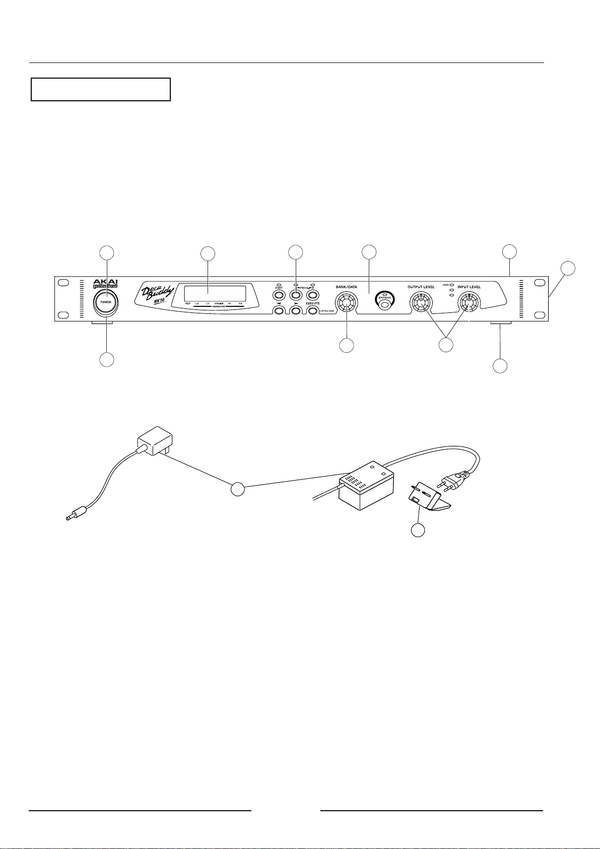
6. FINAL ASSEMBLY BLK
1 SB 820646X BUTTON POWER
2 SE 820647X2 ESCUTCHEON POWER
3 SP 821659X PANEL TOP
4 SE 821661X SHEET DISPLAY
5 EM 821647X IND LCD L1672B1J000
6 SB 821662X BUTTON PUSH (A)
7 SK 821335X KNOB (A)
8 SK 821336X KNOB (B)
9 SH 821663X HANDLE SUPPOTOR
10 SA 821664X FOOT
11-A AX 821687X AC ADAPTER L8020 J (PLUG IN)
11-B AX 821688X AC ADAPTER L8020 C,A (PLUG IN)
11-C AX 821689X AC ADAPTER L8020 E,V,B(CORD IN)
12 EJ 428247N PLUG ADAPTOR ECPL01BKR5 BS5733
Ref.No. Part No. Description
!
!
!
!
!
Other manuals for HV 10
1
Table of contents
Other Akai Music Equipment manuals

Akai
Akai MPD218 User manual

Akai
Akai MPD 32 Manual

Akai
Akai Professional LPK25 User manual

Akai
Akai S1100 User manual

Akai
Akai MD280 User manual

Akai
Akai Professional MPC 1000 Installation guide

Akai
Akai DPS24 User manual

Akai
Akai LPD8 User manual

Akai
Akai MPC Studio mk2 User manual

Akai
Akai SynthStation 25 User manual