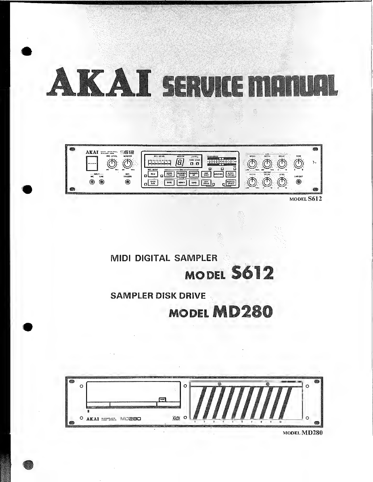
Akai S612 User manual

:
#v©w>
$Mji
MIDI DIGITAL SAMPLER
MODEL
SAMPLER DISK DRIVE
MODEL


ABBREVIATION FOR SERVICE MANUAL
MODEL S612
ABBREVIATION EXPLANATION ABBREVIATION EXPLANATION
ALTER ALTERnating MON MONitor
BUSDIR BUS DIRection RFSH ReFreSH
CASSR CASSette Read RXD Receive Data
CASSW CASSette Write RD RdaD
CH CHannei SHOT one SHOT
cs Chip Select SIN Signal INput
DUB over DUB SLTSL SLoT SeLect
IORQ I/O ReQuest TRANS TRANSpose
LOOP LOOPing TRIG TRIGger
Ml Machin cycle 1TXD Transmit Data
MREQ Memoly REQuest V.REF V.REFerence
MIDI Musical instrument Digital Interface WR WRite
MODEL MD280
ABBREVIATION EXPLANATION ABBREVIATION EXPLANATION
B/A channel B/channel AMTON MoTor ON
C/D Command/Data QD Quick Disk
CE Chip Enable RD ReaD
CRC Cyclic Redandancy Check Character RDDT ReaD DaTa
CS Chip Select RTSA Request To Send A
CTSA Clear To Send ARTSB Request To Send B
Dsystem Data bus RXCA Receive Clock A
DCDA Data Carrier Detect ARXDA Receive Data A
DCDB Data Carrier Detect BSIO Serial Input Output
DIR DIRection SLTSL SLoT SeLect
DTRB Data Terminal Ready BTXCA Transmit Clock A
IEI Interrupt Enable In TXDA Transmit Data A
IORQ Input/Output ReQuest WR WRite
Ml Machine cycle 1WRDT WRite DaTa
MDST Media SeT WRGA WRite GAte
MERQ MEmory ReQuest WRPR WRite PRotect
MFM Modified Frequency Modulation d> system clock

AKAI satuKE mmun
TIONAL)
This additional Schematic Diagram is made for the Main
PCB of model S612.
Use this additional Schematic Diagram with the model
S612 Service Manual which published previously.
DIGITAL SAMPLER
MODEL
ADC0809 [8 BIT A/D CONVERTER]
(IC58)
START CLOCK
<L
IN 0
IN I
IN 2
IN 3
IN 4
IN 5
IN 6
IN 7
AO
AI
A2
ADDRESS
LATCH ENABLE
Vcc GND REF (+) REF OUTPUT
(-) ENABLE
BA9201 [8 BIT D/A CONVERTER]
(IC90 to 95)
DATA IN
I1.
D7D6 D5 D4 D3 D2 Dl DO
<2>


TC74C174P [HEX D-FFs]
(IC61.62, 63)
TC74HC74 [DUAL DFLIP-FLOP] TC74HC175P [QUAD D-FFs]
(IC 17to 19) (IC60)
10 10 20 20 30 30 4D 40 50 50 60 60 CLR2 02 CLK 2PR 210 ?0 20 30 30 40 40
/SHS) (7>—(fi) (iqHF) (I5> FUNCTION TABLE
iINPUTS [OUTPUTS
FUNCTION TABLE
TC74HC138P [3 to 8DEMULTIPLEXER]
(IC11, 12)
INPUTS OUTPUTS |
PR CLR CLK DQ0
LHXX H L
HLX X LH
L L XXH- H-
HHtHHL
HHtLLH
HHLXQO 00
OATA
OUTPUTS
TC74HC1 39P [DUAL 2to 4DEMULTIPLEXERS]
(IC2)
ENABLE 2G
DATA
OUTPUTS
TC74HC157P [2 to 1DATA SELECTORS]
(IC32, 33)
FUNCTION TABLE
INPUTS OUTPUTS
ENABLE SELECT
G1 G2> C8AYO Y1 Y2 Y3 Y4 Y5 Y6 Y7
~X lUT ~X X-HHHHHHHH
LXX XXHHHHHHHH
HLL LLLHHHHHHH
HLL LHHLHHHHHH
HLL HLHHLHHHHH
HLL HHHHHLHHHH
HLH L L HHHHLHHH
HLH LHHHHHHLHH
HLH HLHHHHHHLH
HLH HHHHHHHHHL
FUNCTION TABLE
INPUTS OUTPUTS
ENABLE SELECT
GBAYO Y1 Y2 Y3
HX X H H HH
LLL L HHH
LLHHLH H
LHLH H LH
LHHHHHL
TC74HC245P [QCTAL 3STATE TRANSCEIVER]
(IC25)
DIR At A2 A3 A4 A5 A6 A7 AS GND
TC74HC259P [8 BIT ADDRESSABLE LATCHES] (IC42, 43)
nui >
I.ArCH SEI
TC74HC373 [3 STATE OCTAL D-TYPE LATCH]
I(IC21
)
FUNCTION TABLE
LLBdata to Abus
LHAdata to Bbus
HXIsolation
FUNCTION TABLE
gill

TC74HC4040P [12-STAGE BINARY COUNTER]
(IC23, 24)
UADD-FFs]
FUNCTION TABLE
”INPUTS "" OUTPUTS
CLOCK (io)
CLEAR QL
4HC245P [QCTAL 3STATE TRANSCEIVER]
FUNCTION TABLE
FUNCTION TABLE
OUTPUTS:
ENABLE
G1 G2* :
select:
4HC259P [8 BIT ADDRESSABLE LATCHES] (IC42, 43) X: DON’T CARE
,uPD710540P [PROGRAMMABLE
^PD8253C-2 INTERVAL TIMER]
(IC5, 6, 7, 8)
//PD780C [8 BIT CPU]
(IC1)
16 BIT ADDRESS
BUS WRITE CONTROL
FUNCTION TABLE BEAD CONTROL
INPUTS CHIP SELECT
OUTPUTS DATA BUS
ENABLE CLOCK 16BIT ADDRESS BUS ADDRESS BUS
COUNTER CLOCK
COUNTER OUT
COUNTER SATE
COUNTER CLOCK
BBIT DATA BUS COUNTER OUT COUNTER CLOCK
COUNTER GATE
COUNTER GATE
LATCH STL COUNTER OUT
REFRESH
MACHINE CYCLE ONE
C74HC373 [3 STATE OCTAL D-TYPE LATCH]
C21) //PD8255 AC-2
(IC4 1
)
8USR0 ©
INTERRUPT REQUEST
LATCH
ENABLE NON MASKABLE
INTERRUPT WAIT CONTROL
HUSAK fj)
HALT STATE -.10} HALT BUS AC KNOW (FORE
QS) MR EO
MEMORY BEQUEST WRITE CONTROL LEO DISPLAY DRIVE
LEO DISPLAY DRIVE
inbut/output reoufst
:
IORQ READ CONTROL
-PD8237 AC-5 (IC9, 10) READ CONTROL WRITE CONTROL
[PROGRAMBLE DMA CONTROLHR] CHIP SELECT
I/O READ
ADDRESS BUS
AOORCSS BUS
CLEAR OUTPUT STATE
HALL OUTPUTS ="L”
LNO CHANGE
LADVANCE TO NEXT STATE
Control
Inputs Operation
GDIR
L L Bdata to Abus
LHAdata to Bbus
HXIsolation
Xc
(V) 07 Vcc ©
©D6 WR 0}
©06 RO ©
©D4 CS (21
)
©D3 A l©
®DZ AO ©
(7)Dl CLK2 (w
(J) 00 OUT 2@
(5) CLK oGATE 2
©OUT 0CLK 1©
©GATE 0GATEl ©
g) GND GUT |(J3)
rER FACE]

-L:-X~-ratr,;",: tig~~|~
FUNCTION TABLE
(INPUTS OUTPUTS
|ENABLE |SELECT
G1 G2* CBAYO Y1 Y2 Y3 Y4 Y5 Y6 Y7
XHXXXHHHHHHHH
LX X X XHHHHHHHH
HL L ALLHHHHHHH
HL L 1HHLHHHHHH
HLLHLH H LHHHHH
HL L HHHH H LHHHH
HLHLLHH H HLHHH
HLHLHHRHHHLHH
HLHHLHH H H H HLH
HLHHH H HHHHHHL
FUNCTION TABLE
INPUTS OUTPUTS
ENABLE
G
SELECT
BAYO Y1 Y2 Y3
HXXHHH H
LL L LHHH
L L H H LH H
LHLH H LH
LHHHH H L
FUNCTION TABLE
jINPUTS
Select Strobe
GY
XHL
L L A
HL B
FUNCTION TABLE
INPUT OUTPUTS
QA ~QD
Clear CK Enable Output control
G1 G2 M|N
LIT LL-ID ~4D
LHX--
XH
HXXX-LLLL
-HXZ
XH
GDIR
LLBdata to Abus
LHAdata to Bbus
HXIsolation
TC74HC259P [8 BIT ADDRESSABLE LATCHES] (IC42, 43)
FUNCTION TABLE
CLOCK CLEAR OUTPUT STATE
XHALL OUTPUTS =”L"
fLNO CHANGE
_1LADVANCE TO NEXT STATE
X: DON’T CARE
m
TC74HC373 [3 STATE OCTAL D-TYPE LATCH]
(IC21)
LATCH
ENABLE
OUTPUT 10 10 2D 20 3Q 3D 4D 40 GND
CONTROL
TC74HC374 [3 STATE OCTAL D-TYPE FLIP-FLOP]
(IC54)
Vcc 60 8D 70 70 60 6D 50 50 CLOCK FUNCTION TABLE
Output
Control Clock Data Output
LtHH
LTLL
LLXQo
HX X Z
APD780C [8 BIT CPU]
(IC1)
I6BIT ADDRESS BUS
REFRESH
MACHINE CYCLE ONE
RESET
BUS REOUEST
WAIT CONTROL
BUS ACKNOWIEDBE
WRITE CONTROL
READ CONTROL
^PD8237 AC-5 (IC9, 10)
[PROGRAMBLE DMA CONTROLER]
ADDRESS BUS
END OF PROCESS
ADDRESS BUS
+SV
DATA BUS
DMA ACKNOWIEOGE
DATA BUS
//PD710540P [PROGRAMMABLE
fiPD8253C-2 INTERVAL TIMER]
(IC5, 6, 7, 8)
-E5V
WRITE CONTROL
READ CONTROL
CHIP SELECT
ADDRESS BUS
COUNTER CLOCK
COUNTER OUT
COUNTER GATE
COUNTER CLOCK
COUNTER SATE
COUNTER OUT
/iPD8255 AC-2 [INTER FACE]
(IC41)
OPERATION
BUTTON

(IC32, 33
TC74HC
(IC55)
14)
G
ENABLE
LLBdata to Abus
LHAdata to Bbus
HXIsolation
o
o
I
EFUNCTION TABLE
Output
Control
Latch
Enable
GData 373
Output
LHHH
LHLH
LLXQo
HXXZ
KFUNCTION TABLE
Output
Control Clock Data Output
LtHH
LtLL
LLXQo
HXXZ

JACK
JACK
POWER


cDEf
IC25
rC74HC245P
GHK
KIilLi 1RdLJH IRfcfl
STB
)IC94
BA 92 OI
STB
~) 1C 9 5
\BA 920 I
1C 77
MF6CN-50

B1cij D]E|F|!G
START/
SPLICE
DATA BUS '•:
1
..
no iJ
Uv V
1C 1\
PPD780C-I
CPU j
r\7 (
r
o
ky
UfV?
Ac j,.4MHz
AI5
L-O O—
W—NDO to 7S
JL NDO to 7S
J&T XDO to IS
W\00 to 7s
MXDO to 7S
D0^^7 DO 7jDO^Ot' |
1I00^.7 1DO '-^-7 DO 7
RECT
RECT
VOICE 2
IC 3
TMM2764D 1C 4
HD6850P
>RDX
IC5
j)PD8253C
-2 pPD8253C
-2
1C 7
JJPD7 I054C
i
OUT Of
1C 8
pPD7 1054C
)OUT 0
1C 9
PP08237AC-
5
EP-ROM
AO 'A12
CLK Oto 2(
OUTO to 2(
COUNTER
OUTO to2(
COUNTER
|
RS/RW/CS^
COUNTER
AO ,Al
COUNTER
AO ,Al
DR03 DACK3
DMA
DRQ |DACK |
DMA
REC1
VOICE 6
ADDRESS BUS
\AO r~
8MHz CLOCK
v, 1C 23 tC 24
TC74HC4040P TC74HC4040P IC25
IIUI 1 I 1 I!TC74HC245P IC26
JIPD4I4I6C- IC27
JIPD4I4I6C- IC 28
JJPD4I4 16C- IC 29
JtPD 4141 6C“ IC30
JIP04I4I6C- IC 3I
UPD4I4I6C- IC32
TC74HCI57P 1C 33
TC74HCI57P
R,

iEND r
t
|DEPTH [
|DELAY
[speed
[DECAY |
FILTER [
1

IC56
AM2504C
A/D CONVERTER
mm
!
ID
1C 54 74 H
IQ -v_
C374 P
8Q
o-
0D

MIDI DIGITAL SAMPLER
MODEL S612
SECTION 1OPERATING MANUAL 3
SECTION 2SERVICE MANUAL 27
SECTION 3PARTS LIST 41
SECTION 4SCHEMATIC DIAGRAM AND PC BOARDS
SECTION 5SERVICE BULLETIN
This Manual is FOR INTERNAL USE ONLY and must not be made
available to unauthorized personal. No part of this manual may be re-
produced in any form without permission from AKAI-ELECTRIC CO.,
LTD., Tokyo, Japan.

SAFETY CHECK AFTER SERVICING
Confirm the specified insulation resistance between power cord plug prongs and externally exposed parts of the set is
greater than lOMohms, but for equipment with external antenna terminals (tuner, receiver, etc.) and is intended for
[C] or [a], specified insulation resistance should be more than 2.2Mohms (ground terminals, microphone jacks,
headphone jacks, line-in-out jacks etc.)
PRECAUTIONS DURING SERVICING
1. Parts identified by the Asymbol parts are critical for safety.
Replace only with parts number specified.
2. In addition to safety, other parts and assemblies are specified for conformance with such regulations as those
applying to spurious radiation. These must also be replaced only with specified replacements.
Examples: RF .converters, tuner units, antenna selector switches, RF cables, noise blocking capacitors, noise
blocking filters, etc.
3. Use specified internal wiring. Note especially:
1) Wires covered with PVC tubing
2) Double insulated wires
3) High voltage leads
4. Use specified insulating materials for hazardous live parts. Note especially:
1) Insulation Tape
2) pvc tubing
.
3) Spacers (Insulating Barriers)
4) Insulation sheets for transistors
5) Plastic screws for fixing microswitch (especially in turntable)
5. When replacing AC primary side components (transformers, power cords, noise blocking capacitors, etc.), wrap
ends of wires securely about the terminals before soldering.
060
Observe that wires do not contact heat producing parts (heatsinks, oxide metal film resistors, fusible resistors, etc.).
Check that replaced wires do not contact sharp edged or pointed parts.
Also check areas surrounding repaired locations.
Use care that foreign objects (screws, solder droplets, etc.) do not remain inside the set.
Voltage conversion
Models for Canada, USA, and Japan are not equipped with this
facillity. Each machine is preset at the factory according to its des-
tination, but some machines can be set to 110V, 120V, 220V or
240V as required.
If your machine’s voltage can be converted:
Before conmnecting the power cord, trun the VOLTAGE SELEC-
TOR located on the bottom panel with ascrewdriver until the cor-
rect voltage is indicated.
6.
7.
8.
9.
!| SECTION 1.
|;OPERATING MANUAL
IABLE OF CONTENTS
CONTROLS .4
CONNECTIONS 7
SAMPLING 8
OVERDUBBING 10
SAMPLING BY REC TRIGGER .11
EDIT 12
SCANNING 13
LFO 17
OUTPUT .18
jTRANSPOSE 19
TUNING 20
MIDI 21
MIDI MODE 22
SAVE, VERIFY AND LOAD 23

Controls
MONITOR Control
This control adjusts the monitor level
while sampling alive sound. The
monitor level is not affected by the
output LEVEL control. When sampling
by microphone and the monitor level
is too high, "howling” may result.
REC LEVEL Control
This control adjusts the recording
level of thejincoming signal.
POWER Switch
Use the POWER switch to turn the
power on and off.
Note: Do not attempt to connect
the sampler disk drive
MD280 after the S612 has
been turned on.
MIC INPUT Jack
This jack is used for sampling from a
microphone or aelectric guitar. The
input sensitivity is —63 dB. Connect
astandard 6.3 mm<f> phono plug to
this jack.
LINE INPUT Jack —
This jack is used for sampling the line
out from keyboards or audio equip-
ment, etc. The input sensitivity is
—27 dB. Connect astandard 6.3
mm<£ phono plug to this jack.
Note: When both MIC and LINE
input jacks are used, the
MIC input has priority,
priority.
MIDI GH. Display
Normally, this will indicate the MIDI
reception channel. However the dis-
play will light up to confirm proper op-
eration when saving, verifying and
loading tone data.
*When the power is on, the display
will show "0” (omni on). When the
unit receives MIDI signals, such
as key-on, key-off, etc., the dis-
play will brighten momentarily.
REC LEVEL Indicator
Shows the recording level which can
be adjusted by the REC LEVEL control.
LOOPING Button
Press this button to set the scanning
mode to looping. The LED indicator
will light.
This jack allows the use of afoot
switch to trigger the sampling pro-
cess.
Note: Connect astandard 6.3
mm^ phono plug to this
jack. Use the Akai PS-X80
or the circuit is opened
when the connected switch
is pushed down.
NEW Button
Press this button when you make a
new sample.
*The previous sample will be
erased.
DVERDUB Button
Press this button when you wish to
overdub one or more sounds.
*You can overdub many times.
Press this button to save the sound
data in the S61 2onto disk or tape.
MIDI MONO/POLY Mode Select
Button
This button is used to switch between
the MIDI mono and poly modes. The
Indicator lights when the mono mode
is set.
END Point lever
This lever sets the end-point of the
sampled sound.
MANUAL SPLICE Button
Press this button to set asplicing
point manually. The LED indicator will
light.
START/SPLICE Lever
This lever sets the start/splice point
of the sampled sound.
Note: Normally, this lever sets the
starting point. However,
when the MANUAL SPLICE
button is pressed, it will set
the splicing point.
—ALTERNATING Button
Press this button to set the scanning
mode to alternating. The LED indica-
tor will light.
LFO, SPEED. DEPTH, DELAY controls
Avibrato effect can be added to the
sampled sound by using the LFO.
SPEED —Adjusts the speed of the vi-
brato.
DEPTH —Adjusts the depth of the vi-
brato.
DELAY —Adjust the delay time of the
vibrato.
KEY TRANS Button
Press this button to transpose the
sampled sound. The LED indicator
will light.
MIDI CHANNEL DOWN Button
Press this button to lower the MIDI
channel number.
*Pressing once decreases the
channel by one. Pressing the
button while "0” is displayed on
the MIDI CH .display will revert the
display to "9”.
VERIFY Button
Press this button to verify the sound
data saved on disk or tape.
MIDI CHANNEL UP Button
Press this button to increment the
MIDI channel number.
*Pressing once increass the chan-
nel by one. Pressing the button
while "9" is displayed on the MIDI
CH .display will forward the dis-
play to "0”,
LOAD Button ,
Press this button to load the sound
data, saved on disk or tape, into the
S61 2.
TUNE Control
The sampled sound can be fine tuned
using this control. It will also serve as
apitch control when replaying
sampled sound.
LINE OUT Jack
The monitor/output signal of the
S61 2appears at this LINE OUT jack,
which can be connected to the line
input of mixers or amplifiers.
*Connect astandard 6.3 mm<f>
phono plug to this jack.
Note: This jack is connected in paral-
lel with the LINE OUT jack on
the rear panel.
1—LEVEL Control
This control adjusts the output level
of the sampled sound. The monitor
level is not affected by the output
LEVEL control.
1DECAY Control
This control adjusts the decay efect
of the sampled sound. Turning the
knob clockwise will Increase the
decay time after key-off.
FILTER Control
This control adjusts the low-pass
filtering on the sampled sound. The
replayed sampled sound will become
mellower as the control is turned to-
wards the LOW position.
Other manuals for S612
2
This manual suits for next models
1
Table of contents
Other Akai Recording Equipment manuals

Akai
Akai MPC Live II User manual

Akai
Akai MPC User manual

Akai
Akai UniBass UB1 User manual

Akai
Akai VirtualDJ 8 User manual

Akai
Akai DR16 pro User manual

Akai
Akai Professional MPC 1000 Instruction manual

Akai
Akai S900 User manual

Akai
Akai EWV2000 User manual

Akai
Akai S01 User manual

Akai
Akai MPD 16 User manual