Akai AC-220 User manual

AKAl-01249
AKAi
5ERUl[E
manual
! i
£IUII
li:::iC:::I;
-I
,=,
I I
c::::, I
c::;:, ,=,.
,:,
~-
'
~
,,
I I I
@)
@)
@ I I '1
(Cl
\ @
~---
' l
i
-
·-
: I I j
[illo~~
DIGITAL
AUDIO
MINI
STEREO COMPONENT SYSTEM
MODEL AC-220/SR-225
MODEL AC-320/SR-425

CONTENTS
SAFETY INSTRUCTIONS ...................................................................................... 2
INFORMATIONS ....................................................................................................... 3
SPECIFICATIONS ..................................................................................................4
CONTROLS .............................................................................................................6
I.
DISASSEMBLY...................................................................................................7
II.
PRINCIPAL PARTS LOCATION ......................................................................... 8
111.
CD PLAYER BLOCK ......................................................................................... 10
IV.
ELECTRICAL ADJUSTMENT ............................................................................ 13
V.
PARTS LIST ....................................................................................................... 15
VI.
BLOCK DIAGRAM ............................................................................................ 36
VII.
WIRING DIAGRAM ........................................................................................... 37
VIII. SCHEMATIC DIAGRAM ................................................................................... 38
IX.
PCB COMPONENT DIAGRAM ........................................................................ 42
X.
REMOTE HANDSET MANUAL ......................................................................... 52
XI.
INFORMATION OF TRANSISTOR/ICs ............................................................... 55
XII. ABBREVITIONS............................................................................................. 56

SAFETY
INSTRUCTIONS
PRECAUTIONS DURING SERVICING
1.
Parts identified
by
the & (* ) symbol parts are
critical for safety. Replace them only with parts
whose
numbers are specified.
2.
In addition to safety, other parts and assemblies are
specified for conformance with such regulations as
those applying to spurious radiation.
These must also
be
replaced only with specified
replacements. .
Examples:
RF
converters, tuner units,
antenna
selection
switches,
RF
cables, noise-blocking capacitors,
noise-blocking filters. etc.
3.
Use specified internal Wiring. Note especially:
1)
Wires covered with
PVC
tubing
2) Double insulated wires
3) High voltage leads
4. Use specified insulating materials for hazardous live
parts. Note especially:
1)
Insulating Tape
2) PVC tubing
3) Spacers (insulating barriers)
4) Insulating sheets for transistors
5) Plastic screws for fixing micro switches
5.
When
replacing
AC
primary side components
(transformers, power cords, noise blocking capacitor,
etc.), wrap ends
of
wires securely about the terminals
before soldering.
c::)
C)
6.
Make sure that wires do not contact heat generating
parts (heat sinks, oxide metal film resistors, fusible
resistors, etc.)
7.
Check
if
replaced wires
do
not contact sharply edged
or
pointed parts.
8.
Also check areas surrounding repaired parts.
9.
Make
sure
that foreign objects (screws, solder droplets,
etc.)
do
not remain inside the set.
MAKE YOUR CONTRIBUTION TO PROTECT THE
ENVIRONMENT
Used batteries with the
ISO
symbol for
recycling
as
well as small accumulators
(rechargeable batteries), mini-batteries
(cells) and starter batteries should not
be thrown into the garbage can.
Please leave them at
an
appropriate depot.
SAFETY CHECK AFTER SERVICING
After servicing, make measurements of leakage-current
or resistance
in
order to check
if
exposed parts
are
acceptably insulated from the supply circuit.
The leakage-current measurement should be done
between accessible metal parts, (such as chassis,
ground terminal, microphone jacks, signal input/output
connectors, etc.) and the earth ground through a resister
of
1500 ohm paralleled with a 0.15 µ F capacitor, under
the unit's normal working condition.
The leakage-current should
be
less the
0.SmA
rms
AC.
The resistance measurement should be done between
accessible exposed metal parts and power cord plug
prongs with the power switch "ON" (if included). The
2
resistance should be more than 2.2Mohms.
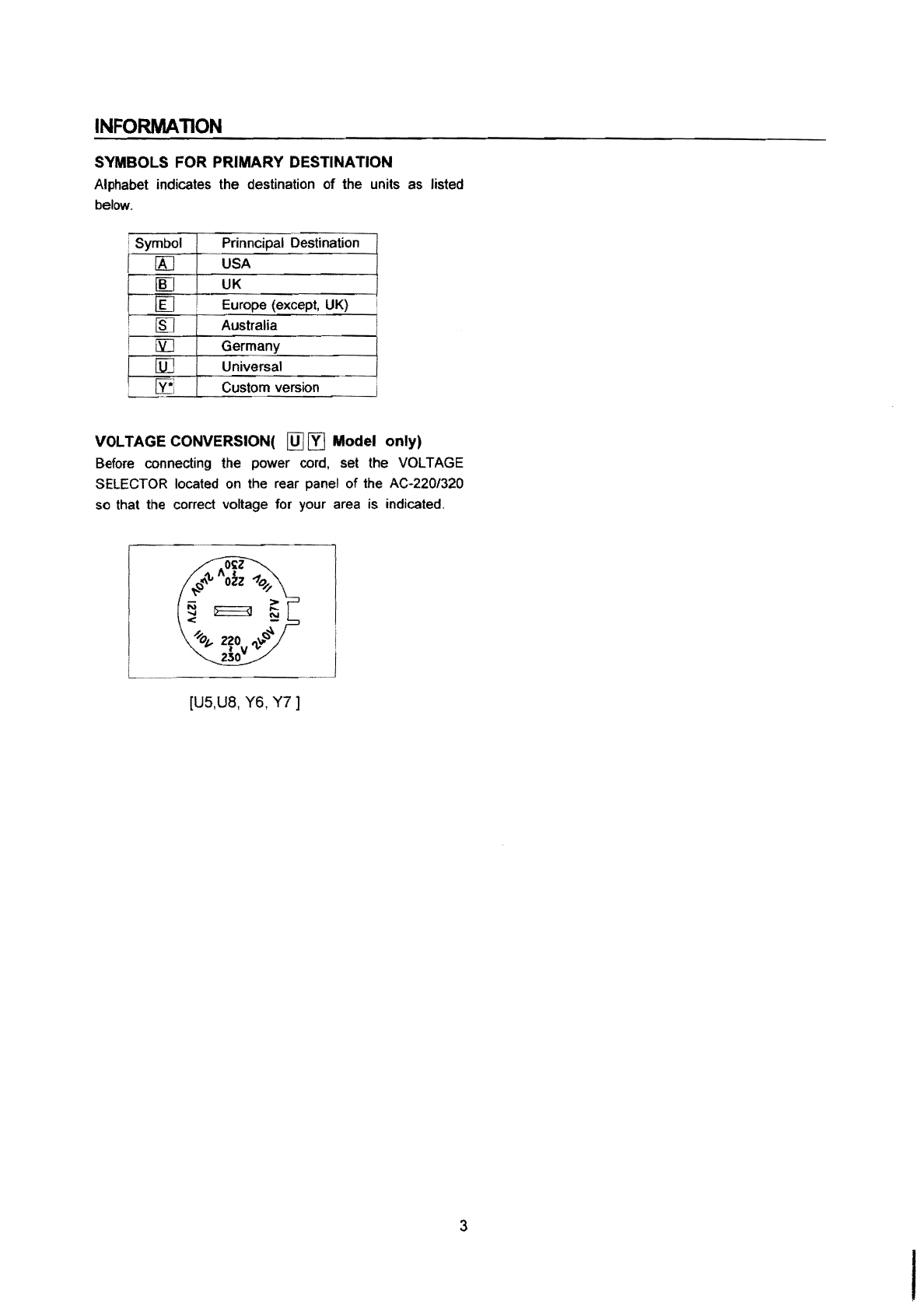
PRECAUTIONS IN REPAIRING
When repairing or adjusting the unit, please note the
following points
1.Do not put excessive pressure on the mechanical"
part (operation part). including the pick-up block, as
extremely high mechanical precision is required
in
these parts.
2.
When the base is removed for repair
or
adjustment.
Make sure that there are no metal objects between
the
P.C
board or the mecha parts and the base.
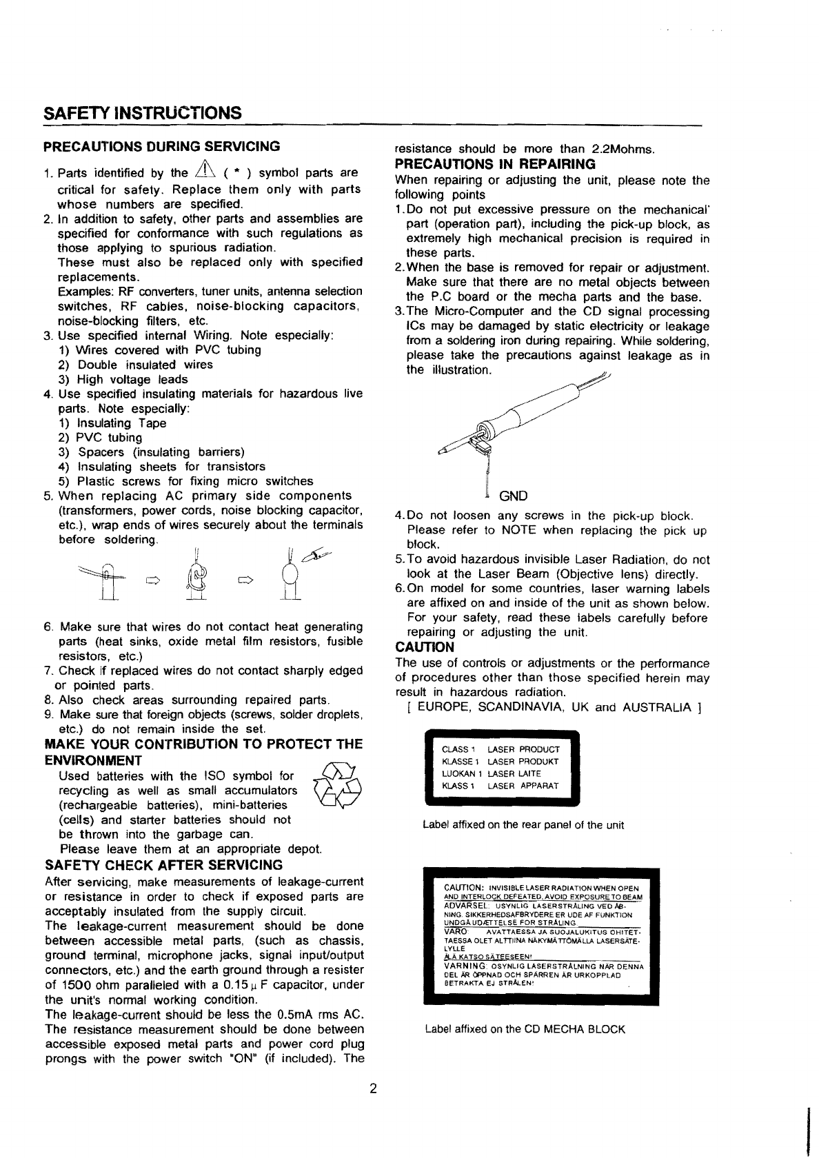
3.
The Micro-Computer and the CD signal processing
ICs may
be
damaged by static electricity or leakage
from a soldering iron during repairing. While soldering,
please take the precautions against leakage as in
the illustration.
GND
4.Do not loosen any screws
in
the pick-up block.
Please refer to NOTE when replacing the pick
up
block.
5.
To avoid hazardous invisible Laser Radiation, do not
look at the Laser Beam (Objective lens) directly.
6.
On model for some countries. laser warning labels
are affixed
on
and inside of the unit as shown below.
For your safety, read these labels carefully before
repairing or adjusting the unit.
CAUTION
The use of controls or adjustments or the performance
of
procedures other than those specified herein may
result
in
hazardous radiation.
[
EUROPE,
SCANDINAVIA,
UK
and AUSTRALIA ]
CLASS 1 LASER PRODUCT
KLASSE
1 LASER PRODUKT
LUOKAN 1 LASER LAITE
KLASS 1 LASER APPARAT
Label affixed on the rear panel of the unit
CAUTION: INVISIBLE LASER RADIATION WHEN OPEN
AND
INTERLOCK DEFEATED.AVOID
EXPOSURET08EAM
AOVARSEL
USYNUG
LASERSTRAUNG
VED
l>e,.
NING SIKKERHEDSAFBRYDERE ER UDE
AF
FUNKTION
UNDGAUDIETTELSE FOR STRALING
VARO
AVATTAESSA
JA
SUOJALUKITUS
OHiTET·
TAESSA OLET ALTTIINA NAKYMi\TTOMALLA l.ASERSATE•
LYLLE
>tA
KA
TSO
SAT€ESEEN'
VARNING: OSYNLIG
LASERSTRALNING
NAA
DENNA
DEL
AA
<iPPNAD OCH SPIIRREN
AR
URKOPPLAD
BETRAKTA
EJ
STRAI..EN!
Label affixed on the CD MECHA BLOCK
I

INFORMA
110N
SYMBOLS FOR PRIMARY DESTINATION
Alphabet indicates the destination
of
the units
as
listed
below.
j Symbol Prinncipal Destination
[A] USA
IJlJ
UK
[[] Europe (except,
UK)
I
~
Australia
I [YJ Germany
[ill Universal
I
[y3
Custom version i
VOLTAGE
CONVERSION(
[QJ
[Yj
Model only)
Before
connecting the power
cord,
set the VOLTAGE
SELECTOR
located
on
the rear panel of the AC-220/320
so
that the correct voltage for your
area
is indicated.
[U5,U8,
Y6,
Y7]
3

SPECIFICATIONS
[Tuner Section]
Frequency range
FM ............................................................................................................................. 87.5-108MHz(50KHz step)
wrviJ
........................................................................................................................................... 530-1710KHz(U8)
................................................................................................................................... 531-1602KHz (except
UB)
LW
144-288KHz(1KHz step) (E1/E2/E3/B1 only)
SW
............................................................................................................. 3.8-12.5MHz(5KHz step) (Y7 only)
USABLE SENSITIVITY
FM ............................................................................................................. (E1/E2/E3/B1) 20.2d8f(IHF,3%THD}
..............................................................................................................(S1/U5/U8/Y6/Y7) 16.2dBf(IHF,3%THO}
wrv!J
..........................................................................................................................................................
500µ
Vm
LW
...........................................................................................................................................................800µVm
SW
..........................................................................................................................................................800µVm
S/N Ratio(IHF)
FM
.................................................................................................................... (MONO 75dB, STEREO 65dB)
MW
...............................................................................................................................................................40d8
LW
................................................................................................................................................................30dB
SW
...............................................................................................................................................................30dB
Stereo separation ........................................................................................................................40dB(at 1KHz)
[AMPLIFIER Section]
Power output ...............................................................................(AC-220} 14W+14W (6ohms,10%THD,EIAJ)
Input sensitivity
10W+10W (6ohms,1%THD,DlN)
(AC-320) 27W+27W (6ohms,10%THD,EIAJ)
20W+20W (6ohms,1%THD,DIN)
Line input(AUX IN) ........................................................................................................................
350mV/47K!l
channel separation ......................................................................................................................................53dB
Frequency response .....................................................................................................
30Hz-60KHz
(-3dB)
[DECK
SECTION]
Track
system .............................................................................................................4track, 2channel system
Frequency response .......................................................................... 40Hz-15KHz (Normal Tape, +3dB/-7dB)
Wow
& Flutter ...............................................................................................................................................
0.1
''lo(WRMS)
SIN
ratio ......................................................................................................................................................................53dB
Total harmonic distortion ...........................................................................................................less than 1%(at 315Hz)
Channel separation ....................................................................................................................................................43dB
4

[CD SECTION]
Pick
up
system ............................................................................................................................3Beam Laser
Sampling frequency ...............................................................................................................................
44.1
KHz
Error correction system ...................................................................................Cross interleave
read
solomon
Number
of
channels ............................................................................................................................
2Channel
Frequency response ........................................................................................................................20Hz-20KHz
Wow
&
Flutter
............................................................................................................................Below measurable limits
SIN ratio .....................................................................................................................................................................83dB
Total harmonic distortion .....................................................................................................................0.035%
(at
1KHz)
Channel separation ...................................................................................................................................73dB(at 1KHz)
Dynamic
range
..........................................................................................................................................
82d8
(at
1KHz}
[GENERAL]
Power
requirement
E1/E2/E3/B1/S1 ...................................................................................................................................
AC
220-230V/50H:z
U5/U8/Y6/Y7........................................................................................................... AC110/127/220-230/240V, 50/60Hz
Power
consumption ................................................................................................................40W/AC-220, 50W/AC-320
Weight ..................................................................................................................................6.6Kg/AC-220,
7.1
Kg/AC-320
[SPEAKER SECTION]
ITEM SR-425
System
Constructions ........................3-way 3-speakers
Woffer Unit ......................................... 135mm Cone type
Midrange Unit .....................................65mm Cone type
Tweeter Unit .......................................20mm dome type (piezo)
System Impedance...........................sn
Maxium Power Input .........................80w
Sensitivity..........................................more than 87dB/w/m
Frequency Response........................60Hz-20KHz
Harmonic Distortion.......................... less than
3%
Enclosure Type .................................bass reflex
type
Units Layout ......................................L/R mirror layout
Dimensison ........................................200(W)X305(H)X265(O)
Net
Weight .........................................3.6Kg/pc
SR-225
3-way 3-speakers
135mm Cone type
65mm
Cone
type
20mm dome type (piezo)
60
30w
more than 87dB/w/m
60Hz-20KHz
less
than
3%
bass reflex type
L/R mirror layout
200(w)X305(H)X235(O)
2.8Kg/pc
For improvement purposes, specifications
and
design are subject to change without notice.
5

• MAIN UNIT
1. Disc tray
2. System FL display
3. Remotesensor
4. TIMERoperation buttons
5.
CH MEMO button
6.
DUBBINGx1/x2button
7.
PHONES
jack
8.
MICjack
9. Mixing control
1
O.
Tape deckI cassettecompartment
11. TapedeckI operation buttons
TP
12. TRAYOPEN/CLOSE button
13. DISC CHANGE button
14. BALANCE button
15. Inputsource
select
buttons
16. Volume control
17. Multi-function buttons
18. DYNAMIC
SUPER
BASS
button
19.
POWER
ON/STANDBY
button
20. Tape deck
II
cassette compartment
21. Tapedeck
II
operation buttons
6

I.
DISASSEMBLY
1·
1.
REMOVE
OF
MAIN
COVER
1)
Remove
the seven
screws
on
back
and
six
screws
on
both sides.
2)
Remove the
MAIN
COVER
Fig.
1-1
1-2.
REMOVE
OF
CD
MECHA
&
FRONT
PANEL
1) Remove
the
CD
door
(B)
2) Remove the
four
screws
(A) on
both
sides
and
disconnect
three
connectors
and
the flat
cable
from the
CD{TUNER!f
APE P.C.B.
3) Remove the·
CD
player
block
4) Remove thethree
screws
(8)
and twoscrews(C)
on both sides.
5) Removethe
FRONT
PANEL
CD
PLAYER
BLOCK
SCREW
(A)
Fig. 1-2
CHASSIS
i3AC'<
Ci-JASS'S-BAC<
CHASS!S-fDTTOM
CASSETTE
v1ECHA
·
SCREW
(B)
SCREW
7

II. PRINCIPAL PARTS
LOCATION
POWER
AMP
EQ
P.C.
BOARD
Fig.
2-1
8
POWER
TRANS
PRIMARY
PC
BOARD
CD/TUNER/TAPE
P.C.
BOARD
CASSETTE
MECHA
KEY
/DISPLAY
P.C.
BOARD

TRAVERSE
MECHA.
PICK UP
BLOCK LOADING
MOTOR CLAMP SW
DISC
DISC
HOLDER
& CLOSE SW
HOLDER
RETAINING
SCREW
SLED
SPINDLE JUNCTION
OPEN
TABLE TABLE
DETECT
MOTOR
MOTOR
PCB
SW
MOTOR
PCB
MOTOR
PCB
Fig. 2·2
CD
PLAYER
BLOCK
9
LOADING TRAY

Ill
CD
PLAYER BLOCK
3-1. DISASSEMBLY
* Remove the
CD
PLAYER BLOCKbefore proceeding.
3-1-1. Removal
of
the TRAVERSE MECHA.
1)
Remove the TRAVERSE COVER by releasing the two
tabs
in
the
direction of the arrow
as
shown
in
Fig.
3·
1.
TAB
TRAVERSE COVER
Fig.
3-1
2) Short
the
circuit on the PICK
UP
BLOCK with solder as
shown in Fig. 3-2.
Note :To protect the laser diode from damage caused by
high voltage static electricity, a part
of
the
PCB on the
PICK
UP
BLOCK
has
to
be
shorted
before
disconnecting the connectors. After replacement, be
sure to connect the
two
connectors and then remove
the solder of the shorted circuit before turning the
power
ON.
ISHORT
POINT!
Short
1:::::111'.;
" with
liiiii:w
solder
PCS
Fig. 3-2
PICKUP
BLOCK
Bottom view
10
3) Disconnect the two connectors carefully.
TRAVERSE
MECHA.
I
~.,
0
r
II
r
~:
Fig. 3-3
4)
Remove the four retaining screws,
then
remov~ the
TRAVERSE MECHA.
5) Proceed
in
the reverse order for installation but never
unsolder the shorted circuit before connecting the three
connectors.
3-1-2. Replacement of the SLED MOTOR
1) Remove the TRAVERSE
ME
CHA (refer to section 3-1-1
).
2) Unsolder the leads of the SLED and SPINDLE MOTORs
then remove the MOTOR PCB.
0
0
SOLDERING PART
0
t?
-,,
•.~
0,-,,-
~~g~E
""
......
_
.....
~
,
rd
RED
\.
c)
MARK
MOTOR PCB
SLED MOTOR
Fig. 3-4
Fig. 3-5

3) Remove the two retaining screws, then remove the SLED
MOTOR.
Next, extract the plastic
gear
from the motor shaft and
attach
it
onto the new motor's shaft.
4) Reassemble in the reverse order.
About the SPINDLE MOTOR:
Replacement
of
the
SPINDLE
MOTOR
itself
is
not
recommended, because adjustment of the
TURN
TABLE
height is quite critical and requires
the
use of a special jig.
3-1-3. Replacement
of
the
PICK
UP
BLOCK
1)
Remove the TRAVERSE MECHA (refer to section 3-1-1
).
2)
While pressing the @ stopper upwards, pull the SLIDE
SHAFT to the right to remove the PICK
UP
BLOCK, then
replace the PICK UP BLOCK.
SLED SHAFT
@STOPPER
PICK
UP
BLOCK
TURN TABLE
Fig. 3-6
3) Reassemble in the reverse order.
3-1-4. Replacement
of
the
LOADING MOTOR
1)
Slide the protruding part of the
GEAR
HOLDER PART in
the direction of the arrow, then pull out the TRAY BLOCK.
Fig. 3-7
11
2) Unhook the LOADING
BELT
with tweezers.
LOADING
BELT
Fig.3-8
3) Unsolder the lead wires
of
the
LOADING
MOTOR with a
soldering iron.
4) While releasing the LOADING
MOTOR's
three retaining
hooks,
push
the motor pully part
down
with
your
middle
finger to remove the LOADING MOTOR, then replace it.
LOADING
MOTOR
Fig:
3-9
GRAY STRIPE
5) Reassemble in the reverse order.
Make
sure
that the wire
with the gray stripe is connected to the mo!Jr•s O marked
terminal when soldering.
3-1-5. Removal
of
the TRAY
BLOCK
1)
If
the
TRAY
BLOCK is in the "in" posaiori, slide
the
protruding part ofthe
GEAR
HOLDER
PARlin the direction
of the arrow and pull outthe
TRAY
BLOCK
slowly
(refer to
Fig. 3-7).
2) In order to disengage the two stoppers,
:a
refully press
the@
part
of
the
TRAY
BLOCK downwaris while pulling
the TRAY BLOCK out as shown
in
Fig.
3-10.
I

STOPPER
@PART
TRAY
BLOCK
4) Remove the
TRAY
BLOCK
by
pulling
it
out carefully.
5) Reassemble in
the
reverse
order
for
installation. When
reattaching the TRAY
BLOCK
to the chassis, carefully
align the guides on both sides of the TRAY
BLOCK
with
their corresponding rails
on
the
chassis. Also,
make
sure
that any
one
of
the reference marks
on
the DISC HOLDER
aligns with the reference
mark
on the LOADING
TRAY.
LOADING
TRAY
DISC
HOLDER
REFERENCE MARK
Fig.
3-11
Next, move the head of the GEAR HOLDER PART
in
the
direction of the arrow before engaging the stoppers
as
shown
in Fig. 3-12.
HEAD
OF
THE
GEAR
HOLDER
PART
Fig. 3-12
3-1-6. Replacement of the TABLE MOTOR
1) Remove the TRAY BLOCK (refer
to
section 3-1-5).
2) Remove
the
DISC HOLDER retaining screw then remove
the DISC HOLDER.
12
T
.
~
TABLE
GEAR
JOINT
DETECT
WORM
MOTOR
PART
PCB
GEAR
3)
Unsolderthe leads
of
theTABLE MOTOR and
remove
the
TABLE MOTOR PCB.
RED
MARK TABLE
MOTOR PCB
Fig. 3-14
HOOK
4) RemovetheTABLE MOTORby pulling it out while opening
the TABLE
MOTOR
retaining hook. Next, remove the
WORM
GEAR
BLOCK
by pulling the GEAR
JOINT
PART
out
and attach it
to
the
new
motor
as shown
in
Fig. 3-13.
5) Reassemble in
the
reverse order.
• When soldering
the
TABLE MOTOR PCB on the TABLE
MOTOR, the
TABLE
MOTOR's red markmust
be
visible
through the hole on the TABLE MOTOR
PCB.
• When attaching the DISC HOLDER on the LOADING
TRAY,
make sure to place
the
DISC HOLDER
so
that
any
one of the three reference marks aligns with the
reference
mark
on the
LOADING
TRAY (any
two
reference holes on the DISC HOLDER align with the
corresponding reference holes on the LOADING TRAY
accordingly).
(Refer
to
Fig. 3-11)

IV.
ELECTRICAL ADJUSTMENT
4-1. CASSETTE DECK ELECTRICAL ADJUSTMENT
PRECAUTIONS: Before adjustment, clean and demagnetizethe heads and tape guides.
ADJUSTMENT STEP:
1.
TESTTAPEffESTCONDTION
2.
MODE
3.
CHECKPOINT/ADJUSTMENTPART
4.
REMARK(•--->
Test
point)
AND RESULT (*-3>-Adjustment part)
2 TAPE
II
NORMAL(x)1
SPEED
1.
3,000Hz Test Tape
2. play
3.
Adjust VR508
4.
Connect a frequency counter to
play L&R output test point TP3
(GND) and TP1 (LCH),
TP2
(RCH) 3000Hz ± 30Hz ,----
1
I
I
1 TAPE
II
HIGH(x)2SPEED
1.
3,000Hz Test Tape
2. Tape
II,
play; Tape
I,
REC
and
HIGH DUBBING
3. Adjust VR509
4.
Connect a frequency counter to
play L&R output test point TP3
(GND) and TP1 (LCH), TP2
(RCH) 6000Hz ± 60Hz
--L-------,--7---7
,---------.---1------1----
CDffUNER/TAPE
PCB
(TOPVIEW)
VR509
VR508
(GND)
TP6
(RCH)
VR501
9~
VR502 (LCH)
@9
I I
I I
L
____
_
CN106
r-0
I
3
BIAS
OSC
FREQUENCY
1.
No
input
signal, normal recording
test tape.
2. REC
3.
Adjust T503
4.
• Connect a frequency counter
between CN106 GND & ERASE
* 96KHz+2/-1 KHz
-f
I
I
I
I
I
I
I
I
__
_
13
I I
c3
6 I
I
TP1
(RCH)
TP2
[3
(LCH)
TP3
(GND)
EQ/AMP
P.C
BOARD
(BOTTOM VIEW)
4
NORMAL
POSITION BIAS
1.
Connect AC Voltmeter between TP6
(GNO) and TP5(Lch), TP7(Rch) Rec
Adjust
VR502(Lch), VR501(Rch) to
10mV
(6.5mV AC-220)
2.
AUX
INPUT 1KHz and 10KHz
LEVEL
-20dB (Ref: TAPE 0dB)
3.
REC
and PB
4.
Confirm the signal level of 1KHz and
10KHz is equal or within +0/-3dB
If
not
good, repeat 1-3 steps

5
HEAD
AZIMUTH
ALIGNMENT(TAPE
I&
II)
1.
10KHz
Test
Tape
2. play
3. Adjust Head Azimuth screw
4. Connect an oscilloscope
to
play L&R
output test point TP1ffP2/TP3
Maximum output level
4-2. CD ELECTRICAL ADJUST
8 FOCUSBIAS
1.
Test disc SONY YEDS-18
2. CD play
3. Adjust VR201
4.
Connect
an
40MHz oscilloscope
the
RF
TP8 & GND, adjust the
RF
signal to maximum
*1.2V p-p(ONLY
FOR
REFERENCE)
AZIMUTH
ALIGNMENT
SCREW
I
I
I
I
I
I
I
I
ICO/fUNER/TAPE PCB
I (BOTTOMVIEW)
I
I
I
I
I
I
I
VR201
---;r-------......__1
__
---;,,1@
I
I
14

V.
PARTS LIST
r---------------------------------
-,
IA
TTENllON
:
:
1.
When placing an order for parts, be sure to listthe part No., Model No. and the description
of
each part. I
I Otherwise, the nondelivery
of
the part
or
the delivery
of
a wrong partmay result. I
I
2.
Please make sure that part
No.
is correctwhen ordering. I
I lfnot, a partdifferentfromthe oneyou ordered may be delivered. I
I
3.
Since the parts shown in parts list
of
preliminary service manual may have been the subject
of
changes, I
I please use this parts list for all future reference. I
L-----------------------------------J
[NOTE]
1.
This parts listlists those parts which areconsidered necessary for repairs. Othercommon parts, such as
resistors and capacitors, are listed in the "Common ListforService Parts"from which these parts should
be selected and stocked.
2.
The Recommended SpareParts listshows those parts
in
the parts listwhich are considered particularly
importantfor service.
3.
Parts not shown
in
the parts listand "Common List for Service Parts" will not in principle be supplied.
r-----------------------------------7
IWARNING I
I & (*)
INDICATED
SAFETY
CRITICAL
COMPONENTS.
FOR CONTINUED SAFETY, REPLACE I
: SAFETY
CRITICAL
COMPONENTS
ONLY
WITH
MANUFACTURE'S
RECOMMENDED PARTS. :
:AVEERTISSEMENT :
1 & (*) IL
INDIQUE
LES
COMPOSANTS
CRITIQUES
DE SOCURITE. POUR
MAINTENIR
LE I
I DEGREDE SOCURITEDE L'APPAREIL, NE REMPLACER
QUE
DES PIOCES RECOMMANDEES I
I PAR LE
FABRICANT.
I
L-----------------------------------J
15 I

1. REMOTE P.C.
BOARD
REF.NO.
CF001
IC001
LED001
PCB
0001
PART NO.
007-300455-63
033-806122-13
130-600101-10
090-385604-01
031-468050-03
210-010101-02S
2. ASS'YKEY/DISPLAY P.C.
BOARD
REF.NO.
0413
0401-412
0414-419
FLT
HSSW
IC401
IC403
L401
MICJACK
MICVOLUME
0401-410
RH
SW402/403/404/414/412/
SW413/414/415/416/417/
SW418/423/424/425/426/427
SW408/419/420/428
SW421/422
X401
X402
PARTNO.
030-560031-00
030-560034-10
030-540034-04
035-131610-00
046-080001-00
033-002401-42
034-B00501-12
005-101056-00
061-121406-00
011-202298-00
031-279014-032
036-600446-01
046-101102-62
046-1
011
02-627
046-100116-48
037-032768-1 0
007-208000-06
3.
ASS'YPOWERAMP/EQ P.C BOARD
REF. NO. PARTNO.
AC CORD(E1/E2/E3/Y7/U5/U8) & 071-669078-00
AC CORD(B1/Y6)
AC COORD(S1)
AC FILTER(E1/E2/E3/B1)
0700/706/707/710/712/726/
D7281729/732/733/734/747/
0750/761/762( for AC-320)
D700/706/707/710/712/714/
D722/726/728/729/732/733/
D7341747( for AC-220)
D7011703/704/705/721
0702/709/715/718/719/720/
0725/730/741-744/0747
for AC-320)
0708/713/731
071-449078-20
071-559078-20
002-300002-09
031-174148-00
030-410062-00H
030-314002-10
030-410062-00H
DESCRIPTION
RESONATOR CRK455 455KHz
REMOTE TRANSMITTER UPD6122G-001
INFRA RED EMITTINT DIODE
EL-1
L1
REMOTE BOARD T=1.6mm 94HB (46X119mm)
TRANSISTOR NPN KTC8050C
REMOTEBATTERYCOVER
DESCRIPTION
LED YELLOWDIODE "MYB31CA"
LED MYB34C YELLOW
LED MGB34D GREEN
"SVA-16MM10"
PUSH
SVV
VPS-800
XL24C01A
MCU
AKWBCA M38184MB-191FP
FIXED INDUCTOR COIL LONELY "SP0203-101J-7"
MIC JACKVERTICAL
HSJ
1406-01-010
ROTARY VOLUME
2KB
"ALPS"
TRANSISTOR NPN SS9014C
REMOCON RECEIVER SPS-446-1
TACK SW 1T1102
TACK SWITCH "I.T.1102P"
TACK SW"TM116A"
CRYSTAL 32.768MHz
CERAMIC RESONATOR CST 8.00 MTW
DESCRIPTION
AC LINE CORD VDE 78" BLACK PLUG & PIN ASS'Y
AC
CORD
BS
STANDW/5A 250V FUSE
MOULDED
PLUG 78" BLACK
AC LINE CORD
SAA
PLUG W/TERMINAL(24183BS-2)
78"
BLACK
LINER FILTER COIL LF-40-102
SILCON DIODE IN4148
ZENER DIODE 7.5V
RECTIFIER DIODE IN4002
ZENER DIODE 6.2V 500mW
16
I

D716 030-410270-01
D717/724 030-410130-00H
D727 030-41 0051-00H
D736-739 & 030-315401-00
D746 030-410039-00H
FUSE
701
(for AC-220) & 082-220500-13
FUSE
701
(for AC-320) & 082-220630-10
FUSE 702
~
082-221600-03
FUSE 703(U5/U8/Y6/Y7) & 082-221000-03
HEAD PHONE 061-122101-00
IC701 033-314052-21
IC706 033-009260-14
IC707(for AC-320) 033-218751-38
IC707(for AC-220) 033-202616-33Q
IC708 033-007338-11
IC709 033-507805-31
IC702-IC704 033-204558-18
IC705(for AC-220) 033-204558-18
IC710(for AC-320) 033-218751-38
Q704/705(for AC-320) 031-211048-25
Q706(for AC-320) 031-241796-00
Q707(for AC-320) 031-221257-00
Q?00/704-709/711/718 031-279014-03V
Q719/731/732(for AC-220)
Q700Q711/718/731/ 031-279014-03V
950/951 (for AC-320)
Q703(for AC-320) 031-440114-05V
Q703/708/724/725/726/ 031-279015-03V
Q730(for AC-220)
Q708/716/724/725/726/ 031-279015-03V
Q730(for AC-310)
Q
710/713/715(for AC-320) 031-232458-25V
Q712 031-278550-04V
Q721
031-278550-03V
Q722/727 031-221335-05
Q728/729 031-278050-0JV
RE701
(for AC-220) 006-110212-04
R847/850/856 & 013-220305-82
R908 & 013-129305-62
4.
ASS'Y CDfrUNER/TAPE P.C. BOARD
co
REF.NO.
PART
NO.
0260/265/266/311/312/313 030-134148-00H
0290-294
030-314002-10
0310
030-410051-00H
04410
030-600048-00
IC200 033-601782-640
ZENER DIODE 27V 0.5W
ZENER DIODE 13V
ZENER DIODE 5.1V0.5W
DIODE IN5401
ZENER DIODE 3.9V
0.5W
FUSE 500mA/250VVDE
FUSE 630mA/250VVDE
FUSE 1.6A/250VVDE
FUSETIA1250V
PHONE JACK3.5 DIA
MC14052BCP DUAL 4-CH MULTIPLEXER
TC9260P ELECTRONTC VOLUME
POWER AMP IC
S1-18751
"SANKEN"
TDA2616Q PHILIPS
AN7338K
4+1
PRESET EQ
L7805CVVOLTAGEREGULATOR
BA4558 DUALAMP
BA4558 DUALAMP
POWER AMP IC Sl-18751 "SANKEN"
TRANSISTOR 2SA1048Y"TOSHIBA"
TRANSISTOR NPN 2SD1796 "SANKEN"
TRANSISTOR PNP 2S81257 "SANKEN"
TRANSISTOR NPN SS9014C SAMSUNG
TRANSISTOR DTC114ES-TP
TRANSISTOR DNP SS9015C SAMSUNG
TRANSISTOR 2SC2458
TRANSISTOR PNP SS8550D SAMSUNG
TRANSISTOR CS8550C
TRANSISTOR 2S81335-T
TRANSISTOR SS8050C
RELAY POWTV-3"OSA-SS-212DM5"
FUSING RESISTOR 22 OHM
1W
FLAME PROOF FUSING RESISTOR 0.2 OHM
1W
DESCRIPTION
SILCON DIODE IN4148
DIODE IN4002
ZENER DIODE 5.1V 0.5W
INFRA RAD LED GL4800
CXA1782BQ/BR
17

IC201 033-209258-61 KA9258O
IC202 033-K02508-64 CXD2508A4
IC204 033-206247-18 MOTOR DRIVER BA6247
IC260 033-204558-18 DUALAMP BA4558
TR200 031-211317-00V TRANSISTOR 2SA1317
TR201/202 031-279014-03V TRANSISTOR NPN SS9014C SAMSUNG
TR260 031-430144-05V TRANSISTOR DTA144ES
TR261/262/290/313/314 031-440114-60 TRANSISTOR DTC114TS
TR292 031-221425-00V TRANSISTOR 2SB1245
TR311 031-233330-00V TRANSISTOR 2SC3330
TR312
031-203536-0SV TRANSISTOR 536FS
TR4410 031-594800-00 PHOTO TRANS DIODE PT 4800
VR2D1 012-103330-06 SEMI-FIXED RES 13-10K OHM
X240 007-201693-06 RESONATOR OSC
CSA
16.93MHz
1UNER
TU-A (E1/E2/B1/E3) 103-146601-04 TUNER ASS'YFM/MW/LWTFCB3E720A
TU-B (Y6/U5/U8/S1) 103-146401-04 TUNER ASS'YFM/AM TFCB1 U717A
TU-C
(Y?)
103-146101-04 TUNER ASS'YFM/MW/SWTECB1S713A
ANTTERMINAL 061-480312-00 ANTENNATERMINAL "HSP-312V-02"
AUXTERMINAL 071-782421-00 PUSH TERMINAL 2PIN HSP-242V1-05 "KUNMING"
0101 030-134148-00H SILCON DIODE IN4148
D102
030-410062-00H ZENER DIODE 6.2V
0502/503
030-130024-00H SILCON DIODE CDG24
Q101/106 031-278050-03V TRANSISTOR 53805DC
Q102/103/105 031-279014-03V TRANSISTOR NPN SS9014 SAMSUNG
Q104 031-279015-03V TRANSISTOR PNP SS9015C SAMSUNG
TAPE
0501/513/514/516/517/518 030-134148-00H SILCON DIODE IN4148
0519
030-410100-00H ZENER DIODE 10V
5%
IC501 033-203246-16 LA3246
IC502
033-207324-14 TA73249
IC503
033-203241-16 LA3241
IC504
033-204558-18 BA4558
IC505
033-201330-13
UPC1330
L502 005-271101-00 FIXED INDUCTOR COIL 270MH
Q503/504/508/511/512/ 031-279014-03V TRANSISTOR SS9014C
Q516/517/521/522/523/
Q525/526/527/530
Q510/513/529 031-279015-03V TRANSISTOR SS90115C
Q518
031-370435-00 TRANSISTOR
80435
0524
031-278550-04V TRANSISTOR SS8550O
T501/502/504/505 007
-1
00100-009 BIAS TRAP COIL 1002-121
T503 002-815100-05 REC OSC IET 510-067
VR5O1/502 112-103541-06 SEMI-FIXED RES 100K
VR5O8 012-103330-06 SEMI-FIXED RESISTOR 10KBVERTICAL
VR5O9 012-502310-06 SEMI-FIXED RESISTOR 5KB VERTICAL
5.
PC
BOARD
BLOCK
REF.NO
PARTNO.
DESCRIPTION
1-a(B
1/E
1/E2/E3 for AC-320) 771-AC32001-04 TC-DK
P.C.
BOARD
1-b(S1/U5/U8/Y6 for AC-320) 771-AC32001-10 TC-DK
P.C.
BOARD
1-c(
Y7
for AC-320) 771-AC32001-13 TC-DK
P.C.
BOARD
1-d(ALLVERSION) 771-AC32001-05 CD CONNECTOR
PC.
BOARD
2-a(B1/E1/E2/E3 for AC-220) 771-AC22001-04 TC-DK
P.C.
BOARD
2-b(S1/U5/U8/Y6 for AC-220) 771-AC22001-10 TC-DK
P.C.
BOARD
2-c(Y7 for AC-220) 771-AC22001-12 TC-DK
P.C.
BOARD
18

3-a(B1/E1/E2/E3 )
3-b(UB
3-c(Y7)
3-d(S1/U5M6)
4-a(B1/E1/E2/E3 for AC-320)
4-b(S1/U5/U8M6 for AC-320)
5-a(B1/E1/E2/E3 for AC-220)
5-b(S1/U5/U8M6 for AC-220)
6-a(B1/E1/E2/E3 for AC-320)
6-b(S1/U5/U8M6 for AC-320)
6-c(
Y7
for AC-320)
7-a(B1/E1/E2/E3 for AC-220)
7-b(S1/U5/U8M6 for AC-220)
7
-c(Y7
for AC-220)
8(ALL
VERSION)
6.
ACCESSARY
REFNO
1
7.0THERS
TRANS.
FORMER
771-AC32001-06
771-AC32001-12
771-AC32001-14
771-AC32001-15
771-AC32001-01
771-AC32001-08
771-AC32001-01
771-AC32001-08
771-AC32001-02
771-AC32001-09
771-AC32001
-11
771-AC22001-02
771-AC22001-09
771-AC22001-11
771-AC32001-03
PARTNO.
790-010103-02
(forAC-220)
(forAC-320)
(forAC-220)
{forAC-320)
& 001-66AC22022
& 001-66AC32022
001-66AA01-06
& 001-66AA02-06
19
KEY
&FLO
P.C.
BOARD
KEY
&FLO
PC.
BOARD
KEY
&FLO
P.C.
BOARD
KEY
&FLO
P.C.
BOARD
AMPMAIN
PC.
BOARD
AMP
MAIN
P.C.
BOA~D
AMPMAIN
PC.
BOARD
AMP
MAIN
PC.
BOARD
POWER
TRANS.
PRIMARY
PC.
BOARD
POWERTRANS.
PRIMARY
PC.
BOARD
POWER
TRANS.
PRIMARY
PC.
BOARD
POWERTRANS.
PRIMARY
PC.
BOARD
POWER
TRANS.
PRIMARY
PC.
BOARD
POWERTRANS.
PRIMARY
PC.
BOARD
POWER
TRANS.
SSECONDARY
PC.
BOARD
DESCRIPTION
REMOCON(RC-S320)
TRANS.
FORMER
230V/50Hz
TRANS.
FORMER
230V/50Hz
TRANS. FORMER MULTIPLE VOLTAGE
This manual suits for next models
3
Table of contents
Other Akai Stereo System manuals