4 D-304267
PowerMaster-33 G2 Installer's Guide
Integrated Siren built
into the panel
The control panel has a high-powered built-in
siren that sounds in case of alarm, enabled by
default.
To define whether or not the control
panel's siren will sound upon alarms: see
KP-250 PG2 Installer’s Guide, section 3.5.5
Configuring Sirens Functionality
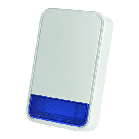
Wired Siren outputs The control panel can operate a wired siren
and strobe devices
Install and connect wired siren: see
section 3.8 Optional Expander Module
Wired zones and
programmable
outputs (PGM)
The control panel can support wired detectors
and control automation devices with
programmable wired outputs.
1. Connect a wired zone or PGM device: see
section 3.4 Adding a Wired Zone and Siren.
2. Program the wired zone: see KP-250
PG2 Installer’s Guide, section 3.4.2 Adding
New Wireless Devices or Wired Sensors
3. Program PGM outputs behavior: see
KP-250 PG2 Installer’s Guide, section 3.7
PGM Output.
Reporting to Private
Users and/or
Monitoring Station by
telephone, SMS and
IP communication
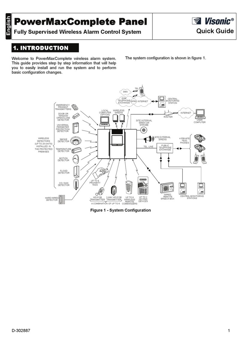
The PowerMaster system can be
programmed to send notifications of alarm
and other events to 4 private telephone
subscribers by voice and also to 4 SMS
cellular phone numbers and to report these
events to the Monitoring Station by SMS,
PSTN or IP communication.
To configure notifications to Private
phones: see KP-250 PG2 User’s Guide,
Chapter 6, section B.12 Programming
Private Phone and SMS Reporting
To configure reporting to the Montioring
Station: see KP-250 PG2 Installer’s Guide,
section 3.6.4 Configuring Events Reporting
to Monitoring Stations
Quick installation with
link quality indication
With PowerG devices, there is no need to
consult the KP-250 PG2 keypad when
mounting a wireless device, because
PowerG devices include a built-in link quality
indicator. Choosing the mounting location is
a quick and easy process.
To choose the ideal location to mount a
wireless device, see Chapter 2 Choosing the
Installation Location.
Device Locator Helps you to easily identify the actual device
displayed on the KP-250 PG2 LCD display.
To read more on the Device Locator: see
KP-250 PG2 User’s Guide, Chapter 3,
Arming and Disarming the System
To use the device locator when bypassing
a zone or when clearing a bypassed zone:
see KP-250 PG2 User’s Guide, Chapter 6,
section B.1 Setting the Zone Bypass Scheme
To use the device locator when conducting
the periodic test: see KP-250 PG2 Installer’s
Guide, Chapter 4 Periodic Test by Installer
Code or KP-250 PG2 User’s Guide, Chapter 8
Periodic Test by User Code.
Guard key-safe PowerMaster is able to control a safe that
holds site keys that are accessible only to the
site's guard or Monitoring Station's guard in
the event of an alarm.
1. Connect the safe to the panel: see
section 3.8 Optional Expander Module
Mounting, Figure 3.8b
2. Configure the safe's zone type to
"Guard Zone": see KP-250 PG2 Installer’s
Guide, section 3.4.2 Adding New Wireless
Devices or Wired Sensors
3. Setup guard code: see KP-250 PG2
Installer’s Guide, section 3.3 Setting Installer
Codes
Arming key External system may control arming and
disarming of the PowerMaster system
Connect the external system output to the
panel: see section 3.8 Optional Expander
Module Mounting, Figure 3.8b
