定格/性能
【 レールへの装着】
(注)
【付属のフェライトコアについて】
SensorCommunicationUnitforSmartSensors
INSTRUCTION SHEET
Thank you for selecting OMRON product. This sheet primarily
describes precautions required in installing and operating the
product:
・This product must be handled by specialists with
electrical knowledge.
・Before using this product, read this sheet thoroughly to
acquire sufficient knowledge of the product.
・For your convenience, keep this instruction sheet at hand
to refer whenever necessary.
2007
Model
ZS-CRT
●Meanings of warning Indication
WARNING
WARNING
Please observe the following precautions for safe use of the product:
(1) Installation Environment
・Do not use the product in environments where it can be exposed to flammable or explosive
gas.
・Do not install the product close to high-voltage devices and/or power devices in order to
secure the safety of operations and maintenance.
・Do not install the product outdoor.
(2) Power Supply and Wiring
・Do not apply voltage exceeding rated voltage or do not use AC power supply.
・If using dedicated flat cables (sheathless or with sheaths) in multiple CompoNet systems, be
sure to keep the dedicated flat cables of each CompoNet system 5 mm or more away from
each other without bundling them to avoid operational unstability due to interference.
・When performing operations described below, turn OFF the power supplies to the PLC’s
main unit and slaves, communication devices, and sensors:
・Assembling the device
・Setting up a DIP switch or rotary switch
・Connecting cables or wiring
・Do not connect any network other than CompoNet.
・Do not connect any model other than allowed
・Be sure to use the communication cables and connectors specified for CompoNet.
・Be sure to confirm locking of devices with the locking mechanism such as a communication
cable.
Indicates a potential hazardous situation that improper
handling may cause death or serious injury.
PRECAUTIONS ON SAFETY
PRECAUTIONS FOR SAFE USE
Be sure to configure the circuits for safety protection such as emergency
stop circuits, interlock circuits, and/or limit circuits to the external control
circuits so that the whole system operates on the safe side even if an
abnormality occurs due to product failure or by external factors.
Not doing so will lead to a serious accident due to abnormal operation.
PRECAUTIONS FOR CORRECT USE
・When performing wiring or construction, be careful to avoid metallic particles from entering
into the unit.
・When wiring a communication cable, observe the following:
・Keep the communication cable away from power lines and/or high
voltage lines.
・Do not bend or fold the communication cable.
・Do not pull the communication cable excessively.
・Do not put anything on the communication cable.
・Be sure to keep the communication cables in ducts.
・Check the wiring and switch settings carefully before energizing.
・Keep communication distances and the number of connected devices within the range defined
by the CompoNet specifications.
(3) Others
・Do not disassemble, repair, or modify the product.
・When performing the following operations, confirm that there is no influence on the
facilities.
・Changing PLC operation modes
・Forced setting/resetting of relay contacts
・Changing set values on the user program, current values, or PLC
operation modes
・Dispose of this product as industrial waste.
・Do not pressurize this product when disposing of it.
Please observe the following precautions to prevent failure to operate, malfunctions, or undesirable
effects on product performance.
1. Instruction site
Do not install the products in locations subject to the following conditions:
・Direct sunlight or near to heaters appliance
・Ambient temperature outside the rating
・Significant temperature change (with condensation)
・Relative humidity outside the rating
・Presence of corrosive or fla mmable gasses
・Presence of dust or iron particles
・Direct vibrations or shock to the body
・Direct splay of organic solvent, water or oil, etc.
・Strong magnetic or electric field.
2. Maintenance and Inspection
Never use paint thinner, benzine, acetone, or kerosene to clean the product.
Wipe out small dirt or dust carefully using a soft cloth containing a small
quantity of alcohol.
Part Names and Functions
Specifications
Item
Compatible network
Communication power voltage
Current consumption for communications
Sensor controller communication method
Connection controller model
(version)
*A modified product, which type name ends with
"−□□" like ZS-LDC11-01, might not be able to
be connected with ZS-CRT.
Function
Indicator
Vibration resistance
Shock resistance
Dielectric strength
Insulation resistance
Ambient temperature
Ambient humidity
Storage temperature
Storage humidity
Installation method
Protecting structure
Material (case)
Accessory
Weight
Specification
CompoNet
14 to 26.4 VDC
200 mA or less
USB2.0 FullSpeed
ZS-LDC□□(ver. 2.300 or later)
ZS-MDC□□(ver. 2.200 or later)
ZS-HLDC□□(ver. 1.030 or later)
ZFV-CA□□(ver. 1.300 or later)
ZG-WDC□□(ver. 1.100 or later)
Monitoring function for measurement results,
Trigger measurement and monitoring function,
Message communication function
MS indicator (green/red), NS indicator (green/red),
and USB indicator (green/red)
10-150 Hz, double amplitude 0.7 mm or 50 m/s
2
8min 10 times each in X,Y and Z directions.
150 m/s
2
, three times each in six directions
(up/down, right/left, and front/back)
1000 VAC, 50/60 Hz, 1 min.,
between the lead terminals and the case
30M or more,
between the lead terminals and the case
0 to +50℃(with no condensation)
25 to 85% (with no condensation)
-15 to 60℃(with no icing or condensation)
25 to 80% (with no condensation)
Fixed to DIN 35 mm rail
IP20
ABS
Instruction sheet, 2 ferrite cores
Approx. 130 g
I/O type
Input
Occupation points
Max. 160points
Slave type
Word slave
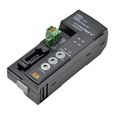
(1) CompoNet Communicating Connector
The connector joint with CompoNet communications cable.
Possible to connect a branch line IDC connector or a
terminal block conversion adaptor (DCN4-TB4)
(2) Sensor Controller Connecting Cable
A cable to communicate with the sensor
Connect this cable with the USB port of the corresponding sensor controller.
(3) Node Address Setting Switch
Set the tens digit of a node address (decimal number) on the
left-hand rotary switch, and the unit digit on the right-hand rotary switch.
(Set the node address within 0 to 63.)
Rotary switch’s settings are read in when the product is turned on.
(4) Function Setting DIP Switch
No function setting. Set all the bits OFF to use.
(5) LEDs for Communications
(1)
(2)
(3)
(4)
(5)
Fatal
error
ON
Red
Minor
communication error
Blinking
If a slight or fatal error occurs, fix the problem first, and then turn on the system again.
If still the error is not solved, replace the unit or the peripheral devices.
Normal Status
Indication
MS
NS
USB
Name
Module Status
(Indicates the status of
the node itself.)
Network Status
(Indicates the status of
CompoNet
communications.)
Sensor Communication
Status
(Indicates the status of
USB communications
with the sensor.)
Color
Green
Red
−
Green
Green
Red
Red
−
Green
Green
Red
Red
−OFF
Blinking
ON
Blinking
ON
OFF
ON
Blinking
ON
OFF
Blinking
ON
Status Definition of status
Normal status
Minor
error
Power
OFF
Online
/accessing
Online
/not accessing
Fatal
communication error
Power
OFF/Offline
Sensor
communications error
Power OFF Power OFF
USB communications error.
The USB cable not connected.
EEPROM settings error.
USB communications error.
Normal USB communication operation
(Message communication in execution)
Normal USB communication operation
(I/O communication in execution.)
Power OFF
/initializing
Communication timeout
Duplicated address
settings detected.
Normal communication operation
(preparing for the access)
Normal communication operation
(accessing)
Power OFF/resetting/initializing
Incorrect settings
The unit hardware error
The WDT timeout.
Normal unit operation
Meaning
Dimensions
89
6
98
35.2
33.26
36.1
Plastic insulating round-shape cord, φ3.8, standard length 750mm
450mm when two ferrite cores are attached (reference size)
98
80.55
61.75
22.4
29.4
36.4
72.5
89
MS indicator
NS indicator USB indicator
Node address setting switch (x1)
Node address setting switch (x10)
CompoNet communication connector
Function setting switch
10 6.5
30
Measures of the mounting hole
58.2
55
10.9
11.9
19.1
23
21
2-M4
21
USB connector (MINI-B)
System Configuration
To use this unit, connect it with the USB connector
of the applicable controller.
Mounting Procedure
[Mounting on the DIN rail]
(1) Fit the hook on the opposite side of the CompoNet connector into the
DIN rail.
(2) Press the hook on the CompoNet connector side into the DIN rail.
(Note)
Follow the order of the mounting procedure as described steps
(1) and (2) above.
Mounting by the reverse steps may decrease the mounting strength.
[Ferrite cores attached]
Install the accessory ferrite cores as shown below.
(Turn the cable once.)
Communications with Sensor
(Unit: mm)
●通信設定について
●接続センサコントローラのチャンネル番号
●動作モードについて
●トリガ計測中の計測値
●計測時間の制約
●バンク入力
●Communication Settings
To connect with a ZS series controller, make the communication settings of the controller
“non-procedual.”
Otherwise, communications is not usable.
●Channel number of connected controller
Connect ”Sensor Controller Connecting Cable” to 0ch’s controller.
This unit can not work, when the cable is connected to any channel’s controller except 0
channel.
●Operation Mode
Operation mode of the sensor controller must be “RUN” mode. If not, communication doesn’t
work.
Do not touch any button on the sensor controller when being connected with this unit.
●Measurement value at trigger measurement
When using trigger measurement of ZG series, read the measurement value after the
measurement is done. (Check the status of GATE output to make sure.)
If reading the measurement value before the measurement is done, the measurement result is
always “error”.
●Limit of measurement settings
When using trigger measurement of ZG series, set “output response time” below 30 seconds.
When ”output response time” is over 30 seconds, communication error would occur at this
unit.
(Output response time = measurement cycle × average number of times. The measurement
cycle can be checked by the ECO monitor in the RUN mode.)
●Bank input
Change setting banks through this unit. When setting banks are changed with bank input of
the sensor controller, communication error would occur at this unit.
Ω
© OMRON Corporation All Rights Reserved.
OMRON Corporation
Suitability for Use
EUROPE
OMRON EUROPE B.V. Sensor Business Unit
Carl-Benz Str.4, D-71154 Nufringen Germany
Phone:49-7032-811-0 Fax: 49-7032-811-199
NORTH AMERICA
OMRON ELECTRONICS LLC
One Commerce Drive Schaumburg,IL 60173-5302 U.S.A.
Phone:1-847-843-7900 Fax : 1-847-843-7787
ASIA-PACIFIC
OMRON ASIA PACIFIC PTE. LTD.
No. 438A Alexandra Road #05-05-08(Lobby 2),
Alexandra Technopark, Singapore 119967
Phone : 65-6835-3011 Fax :65-6835-2711
o
THE PRODUCTS CONTAINED IN THIS SHEET ARE NOT SAFETY RATED.
THEY ARE NOT DESIGNED OR RATED FOR ENSURING SAFETY OF
PERSONS, AND SHOULD NOT BE RELIED UPON AS A SAFETY
COMPONENT OR PROTECTIVE DEVICE FOR SUCH PURPOSES.
Please refer to separate catalogs for OMRON's safety rated products.
OMRON shall not be responsible for conformity with any standards, codes, or
regulations that apply to the combination of the products in the customer's
application or use of the product.
Take all necessary steps to determine the suitability of the product for the
systems, machines, and equipment with which it will be used.
Know and observe all prohibitions of use applicable to this product.
NEVER USE THE PRODUCTS FOR AN APPLICATION INVOLVING
SERIOUS RISK TO LIFE OR PROPERTY WITHOUT ENSURING THAT THE
SYSTEM AS A WHOLE HAS BEEN DESIGNED TO ADDRESS THE RISKS,
AND THAT THE OMRON PRODUCT IS PROPERLY RATED AND
INSTALLED FOR THE INTENDED USE WITHIN THE OVERALL
EQUIPMENT OR SYSTEM.
See also Product catalog for Warranty and Limitation of Liability.
CHINA
OMRON(CHINA) CO., LTD.
Room 2211, Bank of China Tower,
200 Yin Cheng Zhong Road,
PuDong New Area, Shanghai, 200120, China
Phone : 86-21-5037-2222 Fax :86-21-5037-2200
OCT, 2009
NOTICE:
This product meets CISPR11 class A. The intended use of this product
is in an industrial environment only.
Manufacturer:
Omron Corporation,
Shiokoji Horikawa, Shimogyo-ku,
Kyoto 600-8530 JAPAN
Ayabe Factory
3-2 Narutani, Nakayama-cho,
Ayabe-shi, Kyoto 623-0105 JAPAN
TRACEABILITY INFORMATION:
Representative in EU:
Omron Europe B.V.
Wegalaan 67-69
2132 JD Hoofddorp,
The Netherlands
