FONESTAR SCI-705R User manual

SCI-700, SCI-705R,
SCI-710P and SCI-720D
WIRELESS UHF CONFERENCE
SYSTEM
EN Instruction manual

- 2-
We take this opportunity to thank you for buying this product.
We recommend you read the instruction manual before switching on the machine and follow the instructions
that are given. Keep the manual for future reference.
SECURITY AND THE ENVIRONMENT
ELECTRICAL SECURITY
Check that the current in the mains connection where the machine is to be installed corresponds to the
power supply of the machine.
To avoid damaging the equipment, electrical shocks, fire or physical injury when you connect or disconnect
the equipment from the power supply, pull the plug firmly out of the mains socket holding the plug, never the
cable.
Always do this with dry hands.
Keep the power supply cable far from sources of heat. Do not put heavy objects on top of it or change it.
Clean dust and dirt off the power supply cable regularly.
Do not open the machine; you could get an electric shock.
CAUTION
While installing the machine, make sure it is switched off and unplugged.
Do not open the machine. Touching the internal parts is dangerous and you could receive an electric shock.
The machine must not be splashed or dripped on. Never place recipients with liquid inside on the machine.
Do not place anything inside the machine.
LOCATION
Place the equipment on a horizontal surface with enough space around it to allow ventilation.
Avoid direct sunlight, heat sources and excessive dust.
Do not place the machine near magnetic fields or static electricity.
Do not use surfaces which vibrate or receive impact.
Do not pile machines on top of one another.
VENTILATION
Never block or cover the ventilation slits on the machine.
Do not expose it to direct sunlight or place it near sources of heat.
PERIODS OF INACTIVITY
When the machine is not going to be used for a long period of time, disconnect it from the mains.
If you are using an adapter, take into account that it will continue using electricity even if the machine is
switched off. If it is not going to be used for a long period of time, disconnect it from the mains.
THE ENVIRONMENT
To save energy, switch the machine off when you are not going to use it for a long time. The machine could
contain substances that are harmful to the environment or human health. To minimize the effect of these
substances the machine must be correctly managed and recycled when you decide to dispose of it.
When you dispose of it remember: it cannot be thrown into a conventional rubbish bin.
If it contains or uses batteries, these must be disposed of separately.
The machine (without batteries) must be disposed of correctly. Put it in a container specially intended for the
collection of electronic and electrical appliances, at the dump or hand it over to the dealer when you purchase
similar equipment, so that the dealer can dispose of it correctly (at no added cost).
EN

- 3-
SIGNIFICANCE F THE SYMB LS N THE MACHINE*
The symbol formed by the expression “Class 1 laser product” written in a rectangle
indicates that visible or invisible laser radiation could be produced. Avoid direct exposure
to the laser.
The symbol formed by a ray of lightening inside a triangle shows that the machine has
connection terminals or a circuit with areas with a current which could cause an electric
shock, even in normal working conditions.
The symbol formed by an exclamation mark in a triangle shows that the instruction manual
must be referred to for information on how the machine works and its use.
The symbol formed by one square inside another square shows that the machine has
double electrical insulation.
The European Community symbol shows that the machine complies with the current
European Union legislation, as well as its transposition to local legislation.
The symbol of a rubbish bin crossed out and over a horizontal line shows that when the
product is disposed of it must be done properly, placing it in a special selective electronic
and electrical equipment container or through a dealer when purchasing a similar product,
at no additional cost. It also shows that the machine was put on the market after 13th
August 2005 (European Community Directive 2002/96/CE of Electrical and Electronic
recycling, and its Spanish equivalent R.D.208/2005).
In accordance with what is set out in the aforementioned decree, FONESTAR is registered
in the RAEE (Registro de Aparatos Eléctricos y Electrónicos) in a special section REI
(Registro de establecimientos Industriales), with the entry number 001851.
The symbol RoHS (Restriction of Hazardous Substances) shows that the product has
been designed and manufactured restricting the use of certain dangerous materials
(Directive 2002/95/CE on the restriction of certain dangerous substances in electrical and
electronic appliances, and its transferal to the Spanish regulations, R.D.208/2005).
*It is possible that some of these symbols do not appear on the machine.
EXEMPTI N F LIABILITY
The characteristics of the equipment and the content of the manual can change without forewarning.
F NESTAR, S.A. does not assume responsibilities regarding the inappropriate use of the equipment or the
information supplied in this instruction manual, and specifically disclaims any implied liability for marketability
or fitness for any other use.
All rights reserved by F NESTAR, S.A.
DESCRIPTI N
Wireless conference system in UHF 863-865 MHz, which combines the characteristics of a conference
system (priority and selection of maximum number of open microphones) with those of a wireless microphone
system (mobility and easy installation).
The control unit SCI-700 has a capacity for 6 SCI-705R receiver modules. The conference system can be
increased with another control unit taking the capacity of the system up to a total of 12 microphones. ust
one SCI-710P president microphone can be used with up to 11 SCI-720D delegate microphones. The
microphones are switch activated and the president microphone has priority and control over the delegate
microphones.
EN

The most important characteristics of the wireless system are described below:
SCI-700 Control Unit
- Micro-processed control unit.
- Capacity for 6 receiver modules.
- Priority control.
- Selector for maximum number of simultaneously open microphones.
- Switch activated microphones.
- Can be increased with another additional secondary control unit (12 receiver modules in total).
SCI-705R Receiver Module
- UHF 863-865 MHz receiver module.
- Information display with (RF) radio frequency signal, (AF) audio frequency signal and frequency reception
indicators.
- Automatic and manual transmission channel selection.
- Squelch adjustment.
- Control block.
- IR channel transmission to the wireless microphone.
SCI-710P Wireless desktop president microphone
SCI-720D Wireless desktop delegate microphone
- Wireless table-top UHF 863-865 MHz microphone.
- President microphone with priority and control over delegate microphones.
- Switch activated.
- Gooseneck microphone.
- Metal base.
- LED power ring.
- Low battery indicator.
- IR receiver for transmission channel reception.
- 50 m reach (in favourable conditions, with no obstacles).
C NTR LS AND FUNCTI NS
SCI-700 C NTR L UNIT
FR NT PANEL
- 4-
EN

EN
- 5-
1.P WER: on/off switch.
2. MASTER: control unit output volume control.
3. CHANNEL M DE: selector for the maximum number of microphones that can be open at the same
time. Try to choose the lowest number of microphones possible to improve the S/N ratio of the system.
4. PHONES VOL: headphone output volume control.
5. PH NES: headphone output.
6. MASTER-SLAVE: main and secondary unit LED indicators. If the MASTER LED indicator is alight, it
shows that the system is either individually connected or is the main unit. If the SLAVE LED indicator is
alight, it shows that it is the secondary unit. In the case of both indicators being alight, there is an error
in the system connection and it should be reconnected.
7. IR: infrared transmitter for sending the transmission channel to the microphones.
8. LED indicator showing the active microphones at that moment.
9. Receiver aerials for the microphone signal.
10. Blank panels for uninstalled receiver module holes or SCI-705R receiver modules.
BACK PANEL
1, 7. AERIAL A, AERIAL B: aerial connectors, supplying a +8 V DC voltage, 150 mA phantom for the power
supply of an aerial amplifier.
2. LINE UT: unbalanced audio output with 6.3 mm mono jack connector.
3. BALANCED: balanced audio output with XLR connector.
4. LEVEL: audio signal output level selector. It chooses the output level depending on the sensitivity level
of the input connected to the system. 0 dB (1 V), -10 dB (350 mV) or -20 dB (100 mV).
5, 6. NETW RKING UT, NETW RKING IN: extension connector for connecting the main and the
secondary control units in cascade.
8. 110-240 V AC: AC power supply socket.

SCI-705R RECEIVER M DULE
1.- RF: RF radio frequency signal level indicator.
2.- AF: AF audio signal level indicator.
3.- Module operating frequency indicator.
4.- UP, D WN: module operating frequency, channel, squelch level (SQ) selection buttons and button block.
See INSTRUCTIONS FOR USE section for more information.
5.- IR/SET: menu option selection button and sending of channel to microphone via IR. See INSTRUCTIONS
FOR USE section for more information.
SCI-710P and SCI-720D WIRELESS DESKT P PRESIDENT AND DELEGATE MICR PH NES
1.- P WER: on/off switch.
2.- LED power ring.
3.- BATT L W: LED battery indicator. On switching on the microphone, it will light up a few seconds,
showing that the batteries are charged. If the indicator stays on, the batteries need to be replaced.
4.- PRI: voice priority control on the president microphone. Pressing this button the rest of the delegate
microphones are deactivated and only the president microphone can be used. 5 seconds after
releasing the button the microphones can be reactivated.
5.- Gooseneck microphone.
6.- RF Aerial.
7.- IR signal receiver for receiving the transmission channel from the receiver module (central unit).
8.- Metal base.
- 6-
EN

EN
- 7-
9.- Battery holder compartment for 2 x 1.5 V LR6-AA batteries.
C NNECTI N
Connection between SCI-700 units
Place the systems where you want them to be installed. Before switching them on, make the connections
as shown in the following example.
Example of the installation of 2 SCI-700 control units
Firstly, connect all the SCI-700 unit aerials. If the microphones are far from the control unit, you might need
an aerial signal amplifier to receive the signal with an appropriate level, for example model AMP-800S. If you
are going to use more than 6 microphones, you will need two control units.
The audio output of each control unit must be connected to the audio mixer (cables included).
The communication of control signals between both units is made through the NETW RKING UT
connector of the main unit and the NETW RKING IN of the secondary unit.
Lastly, connect the power supply cable from each unit to the mains.

INSTRUCTI NS F R USE
INSTALLATI N F RECEIVER M DULES SCI-705R
The conference system lets you use up to 12 wireless microphones which have to be accompanied by
their respective receiver modules.
To extract or insert receiver modules, you must remove the lid from the control unit.
Remove the screw from the top in order to extract the module and push it outwards.
To insert a module, you must remove the blank panel from the hole in the receiver module and insert the
receiver module making the hole from the screw coincide with the hole in the chassis hook. To do this the
hook on the chassis has to be introduced into the slot in the back panel of the module, above the
connector.
SETTING THE MAIN UNIT
After making the connections and selecting the operating mode, move the volume controls to their minimum.
Firstly, switch on the MASTER main control unit and then the SLAVE secondary unit.
The LED MASTER and SLAVE indicators show if the control unit has been selected as the MASTER or SLAVE.
On the main control unit, with the CHANNEL MODE button, choose the maximum number of open
microphones. Try to choose the lowest number of microphones possible to achieve the best s/n ratio. The
choice will be memorised for the next time the system is switched on.
PUTTING THE MICR PH NES INT PERATI N
Insert the batteries in the wireless table-top microphones and switch them on.
The LED battery indicator, found on the frontal of the microphones, will light up for a few seconds and then
it will go off again if the batteries are acceptable. If the light stays on, change the batteries for some news
ones.
The LED ring on the microphone will be alight while the microphone is activated.
IR SENDING F THE TRANSMISSI N CHANNEL BETWEEN RECEIVER M DULE AND
MICR PH NES
Place the IR sensor of the switched off microphone opposite the unit IR sensor. Briefly press IR/SET on the
module that you wish to connect and wait for the word TRAN to appear on the display. Switch the microphone
on and wait.
If it has worked correctly, the IR sensor light will blink once and the receiver module will show the RF signal
level. The operating frequency will also appear automatically.
N TE: Take into account that the president microphone must be connected firstly and it must be connected
to the first module.
The RF signal level received is shown on the receiver module of each microphone. The AF indicator shows
the audio signal level.
When the previous steps have been followed, adjust the MASTER volume to the desired level.
The following is the order of the receiver modules within the control unit and what corresponds to the open
microphone LED indicators:
- 8-
EN

EN
- 9-
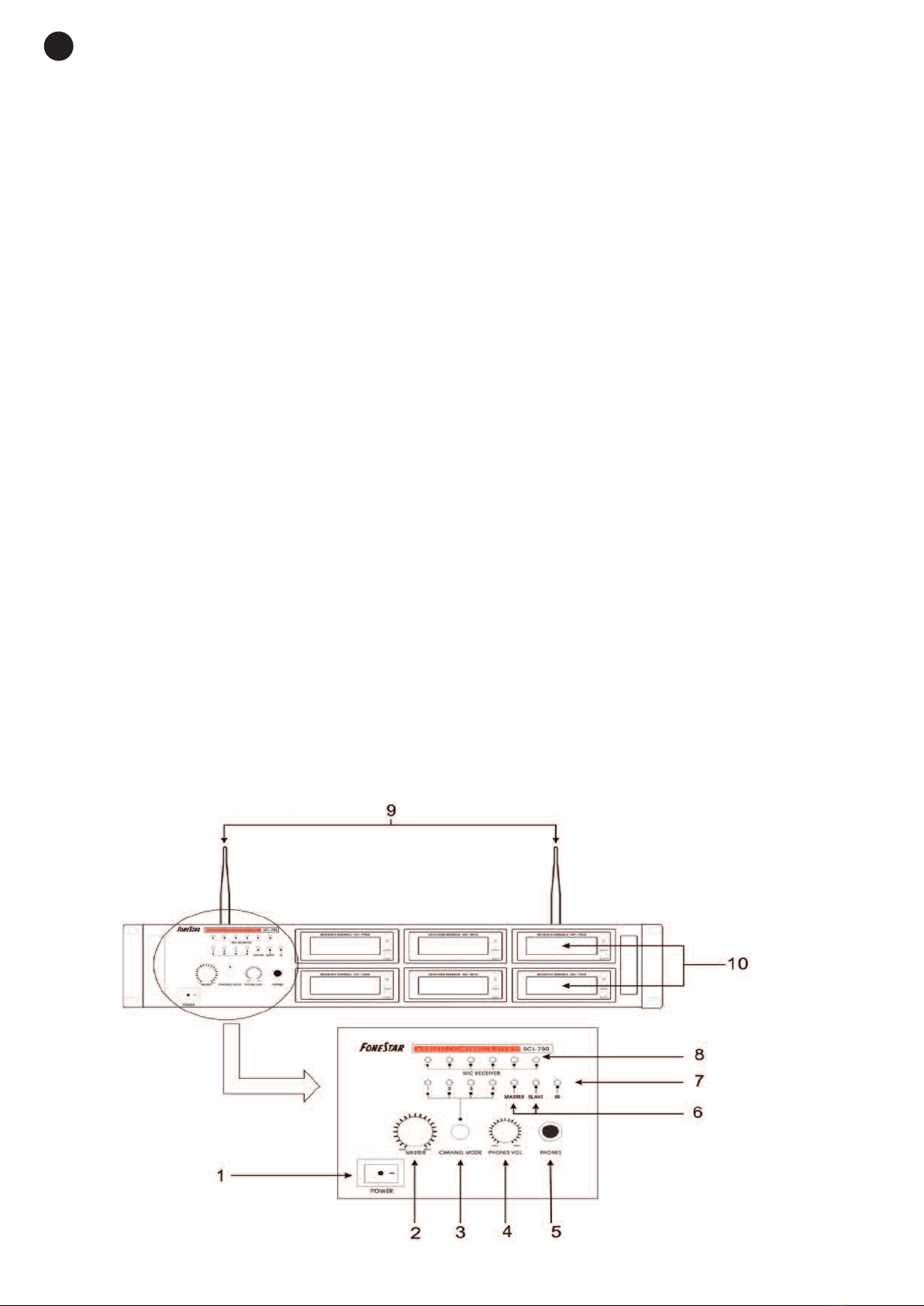
The operating frequency for the receiver module can be chosen manually. To do this, press down the IR/SET
button for a few seconds. With the UP/DOWN keys select the TURN option and press the IR/SET button
again. Afterwards, with the UP/DOWN keys choose the desired operating frequency for that module. After
changing the transmission frequency, the new transmission channel must be sent to the microphone using
IR.
The operating frequency for the receiver module can be chosen from the three pre-tuned channels in each
receiver. To do this, press down the IR/SET button for a few seconds. With the UP/DOWN keys choose the
corresponding option, which in this case is CHAN, and then press the IR/SET button again. Then use the
UP/DOWN keys to choose the desired channel for that module and press IR/SET to select it. After changing
the transmission channel settings, the new channel must be sent to the microphone using IR.
Note: The channel frequencies for each module depend on their position within the control unit.
SQUELCH ADJUSTMENT
The squelch adjustment allows one to adjust the output level to decrease noises.
Maintain the button IR/SET pressed down for a few seconds. With the UP/DOWN keys select the
corresponding option, in this case SQ, and then press the IR/SET button again. Next, with the UP/DOWN
keys, select the SQ level necessary (between 0 dB and 20 dB). Press IR/SET again to save the setting. The
higher the squelch value, the lower the receiver sensitivity (and the noise). Therefore, the operating area of
the system is reduced. Turn the squelch level to its minimum before switching the receiver on and adjust it,
if necessary, to reduce noise in the signal received.
BL CKING THE RECEIVER M DULES
By blocking the receiver modules, the channel or frequency cannot be changed in any of them. To do this,
maintain the IR/SET button pressed down for a few seconds. With the UP/DOWN keys select the LOCK
option and press the button IR/SET again. Then, using the UP/DOWN keys select LOCK ON to block the
modules. To unblock you need to go back into the LOCK menu and select LOCK OFF in the same way as
before.
ADVICE T ACHIEVE THE BEST RESULTS
- Use alkaline batteries.
- Remove obstacles between the receiver and the transmitter.
- The distance between the receiver and the transmitter must not be very big or less than 3 metres.
- The receiver aerial must be far away from metal surfaces.
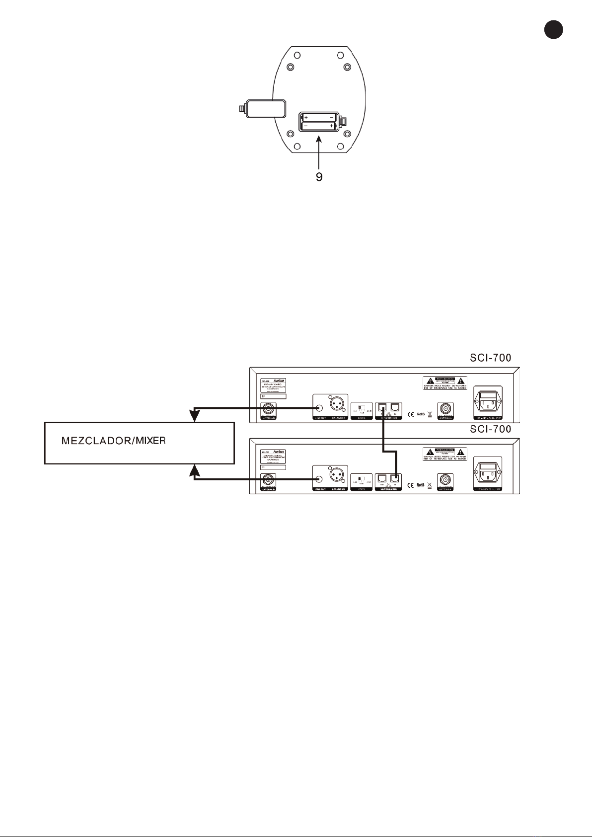
- The interconnection cable for the secondary/external control unit must not be longer than 1.5 m.
- The microphone capsule must be approximately 10 or 15 cm for the speaker’s mouth.
- The output signal level must not be very high otherwise the signal will be distorted.
However, on the other hand, if the output signal is very low, the S/N ratio will decrease and the noise will in-
crease. To adjust the output level to a correct value, we must adjust the mixer level to a standard level, for
example 0 dB gain, and adjust the conference system output volume in such a way that when we speak into
the microphone with a loud voice no distortion is produced.
- Switch the transmitter off after use, and if it is not going to be used for a long time, remove the battery.

EN
- 10 -
SPECIFICATI NS
SCI-700
CHARACTERISTICS Micro-processed control unit.
Capacity for 6 receiver modules.
Priority control.
Selector for the maximum number of operating microphones.
IR frequency selection.
Can be increased with a second control unit (12 receiver modules in total).
RESP NSE 50-18 000 Hz
C NTR LS On/off switch
General volume (MASTER)
Selector for the maximum number of operating microphones
Headphone output volume
Output level selector
INDICAT RS LED power indicator
LED open microphone indicator
LED maximum number of operating microphones indicator
LED main or secondary/external unit indicator
INPUTS 6 wireless microphone receiver modules
2 TNC 50 Ω aerials
Control unit interconnection, R -45
IR transmitter for sending the transmission channel to the microphones
UTPUTS 1 balanced mic., XLR 200 Ω 1V, 350 mV or 100 mV selectable
1 balanced line, 6.3 mm mono jack, 5KΩ 1 V, 350 mV or 100 mV selectable
1 headphones, 6.3 mm stereo jack
P WER SUPPLY 110-240 V AC,15 W
DIMENSI NS 483 x 89 x 310 mm depth. 2U 19” rack
WEIGHT 5.5 kg (with 6 receiver modules)
ACCESS RIES 2 mounts to install in a 2U 19” rack
2 aerials
1.2m audio cable, 6.3 mm mono jack to 6.3 mm mono jack
1 m interconnection cable, CAT-5
Blank panels for empty receiver holes (in this case)
PTI NAL SCI-705R:UHF wireless conference system receiver module
SCI-710P: Wireless desktop president microphone
SCI-720D: Wireless desktop delegate microphone
AMP-800S: Aerial amplifier
CAB-05M, CAB-1M: 0.5 m or 1 m aerial cables

EN
- 11 -
SCI-710P SCI-720D
CHARACTERISTICS Wireless president microphone.
Priority and control over delegate microphones.
Switch activated.
Gooseneck microphone.
Metal base.
12 available channels.
IR sensor for receiving the transmission channel.
Wireless delegate microphone.
Switch activated.
Gooseneck microphone.
Metal base.
12 available channels.
IR sensor for receiving the transmission
channel.
CAPSULE Unidirectional electret condenser
C NTR LS On/off switch
Priority
On/off switch
INDICAT RS LED power ring
LED low battery indicator
RF P WER 10 mW maximum
P WER SUPPLY 3 V DC: 2 x 1.5 V LR6-AA batteries (included)
DIMENSI NS Gooseneck microphone: 440 mm
Base: 122 x 50 x 150 mm depth
WEIGHT 1 kg
ACCESS RIES Windshield
SCI-705R
CHARACTERISTICS UHF receiver module.
For UHF wireless conference system control unit.
PLL tuner.
IR transmission of the channel to the microphone.
C NTR LS Channel selection and blocking
Squelch adjustment
RESP NSE 50-18 000 Hz
INDICAT RS LCD screen, channel visualization, RF signal level and AF level
ALIMENTACIÓN Supplied by the control unit
DIMENSI NS 90 x 37 x 95 mm depth
WEIGHT 0.5 kg

ES
- 12 -
ES
- 12 -- 12 -
ES
- 12 -
EN
DECLARATI N F C NF RMITY
FONESTAR declares, under its own responsibility, that the UHF wireless conference system composed of models SCI-700,
SCI-705R, SCI-710P and SCI-720D complies with the European Parliament and Council Directive 1999/5/EC of 9th March
1999, transposed to Spanish legislation in the Spanish Real Decreto 1890/2000, of 20th November.
This telecommunications system is authorized in any country in the European Union and does not require a license for its
use.
List of standards applied test
Standards Area Compliance with the essential requirement 1995/5/CE
directive
IN 300 220-3 V1.1.1 (2000-09) R&TTE Section 3.2 1999/5/CE directive
IN 300 440-2 V1.1.1 (2001-09)
IN 301 489-1/-3 V1.4.1 (2002-08) EMC Section 3.1b 1999/5/CE directive
EN 60950 ELECTRICAL SAFETY Section 3.1a 1999/5/CE directive
Santander, 27th May 2011
uan Vallejo
Technical Engineer, Sales Department
WARRANTY
This product has been tested and has passed the corresponding quality control prior to being put on the market.
F NESTAR guarantees the suitability of the product for its specified use during a period of 2 years from the delivery date
and commits itself to repair or substitute the goods as expressed in the Spanish law ‘La Ley General para la Defensa de los
Consumidores y Usuarios, Real Decreto Legislativo 1/2007 16 Noviembre.
The lack of conformity in the first six months after purchase, due to a manufacturing defect, will be rectified with no more
than showing the proof of purchase. After six months F NESTAR reserves the right to demand proof of the product being
sold with that problem.
This warranty does not include damage produced by: inappropriate use or negligence, accidents, worn out parts due to use,
breakages, burns, spilt liquids or other substances, excessive humidity, battery deterioration and internal manipulation of the
device, the software or its components by unauthorized persons, and in general any use that is unrelated to the nature and
purpose of the product.
If any service is needed during the warranty period because of lack of conformity, please contact the business or distributor
where the product was purchased in no more than 2 months after being conscious of the problem. It is only necessary to
contact F NESTAR if it is impossible or imposes an undue burden for them to solve it.
To benefit from this warranty it is necessary to show the proof of purchase with the date clearly visible, with no corrections or
crossing out.
This document adds information, and never decreases the consumers’ rights, which in all cases are protected by the Spanish
law ‘La Ley General para la Defensa de los Consumidores y Usuarios, Real Decreto Legislativo 1/2007 16 Noviembre’.
F NESTAR is a member of ECOEMBALA ES ESPAÑA, S.A. “ECOEMBES”, with number 03497 and all our
products carry the symbol, backed by our membership and subscription to the above mentioned organization
with the recycling and subsequent management of our packaging.
Manufactured in China - FONESTAR S.A. - NIF A28780443 - Apartado 191 - 39080 - Santander, Cantabria, (España)
www.fonestar.com
This manual suits for next models
3
Table of contents
Other FONESTAR Conference System manuals

FONESTAR
FONESTAR SCD-600 User manual

FONESTAR
FONESTAR SCD-600 User manual

FONESTAR
FONESTAR SCD-600 User manual

FONESTAR
FONESTAR SCI-750 User manual

FONESTAR
FONESTAR SCF-500 User manual

FONESTAR
FONESTAR SCI-700 User manual

FONESTAR
FONESTAR SCI-750 User manual

FONESTAR
FONESTAR SCF-550 User manual

FONESTAR
FONESTAR SCF-550 User manual

FONESTAR
FONESTAR SCD-600 User manual