AKG D 40 User manual

D40
BEDIENUNGSANLEITUNG . . . . . . . . . .S. 2
Bitte vor Inbetriebnahme des Gerätes lesen!
USER INSTRUCTIONS . . . . . . . . . . . . . . .p. 13
Please read the manual before using the equipment!
MODE D’EMPLOI . . . . . . . . . . . . . . . . . . . . .p. 24
Veuillez lire cette notice avant d’utiliser le système!
ISTRUZIONI PER L’USO . . . . . . . . . . . . .p. 35
Prima di utilizzare l’apparecchio, leggere il manuale!
MODO DE EMPLEO . . . . . . . . . . . . . . . . . . .p. 46
¡Sirvase leer el manual antes de utilizar el equipo!
INSTRUÇÕES DE USO . . . . . . . . . . . . . . .p. 57
Favor leia este manual antes de usar o equipamento!

Seite
1 Sicherheitshinweis/Beschreibung ..........................................................3
1.1 Sicherheitshinweis ........................................................................3
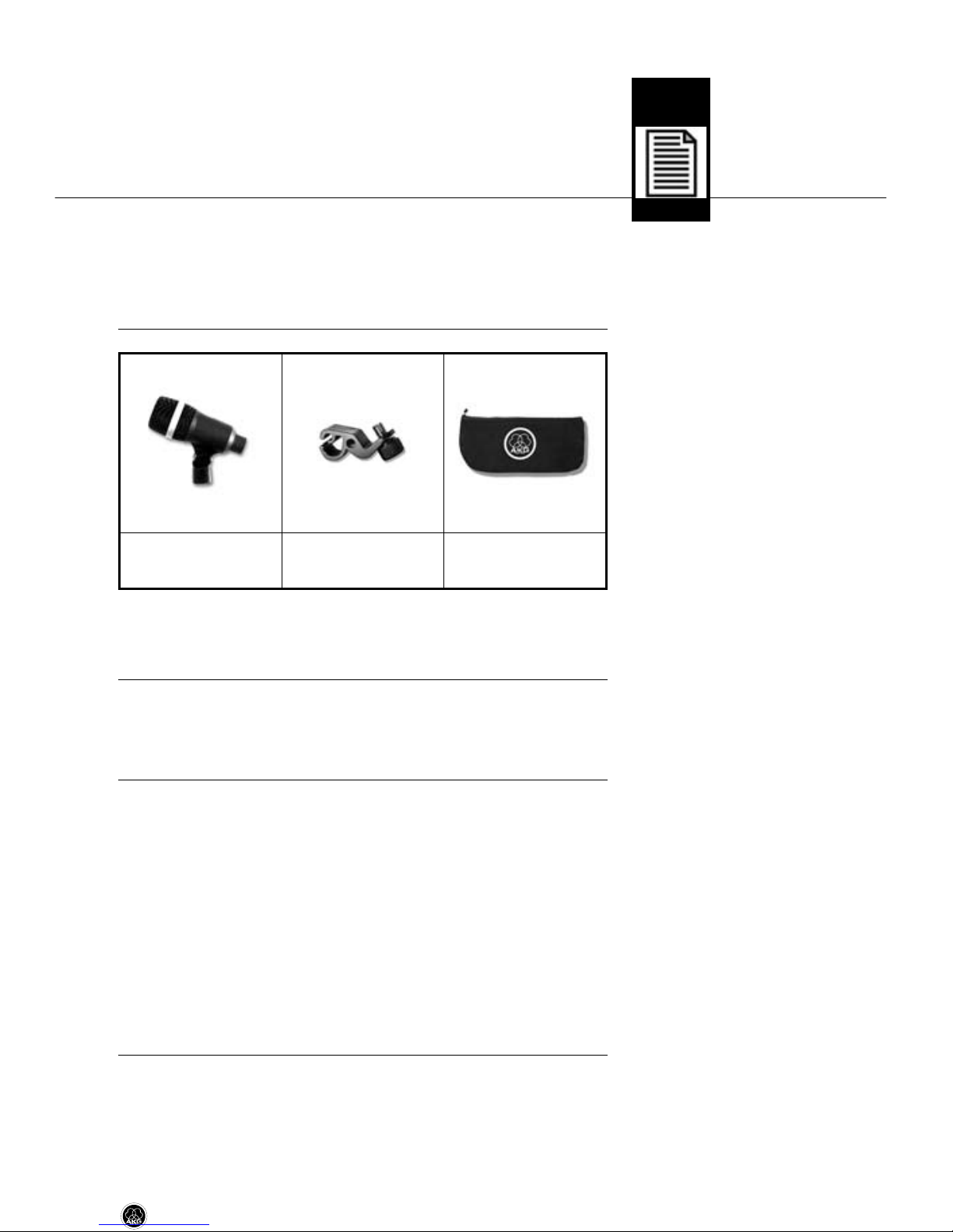
1.2 Lieferumfang ................................................................................3
1.3 Optionales Zubehör .......................................................................3
1.4 Besondere Merkmale.....................................................................3
1.5 Kurzbeschreibung .........................................................................4
2 Anschluss................................................................................................5
3 Anwendung.............................................................................................6
3.1 Einleitung .....................................................................................6
3.2 Saxophon .....................................................................................6
3.3 Trompete......................................................................................7
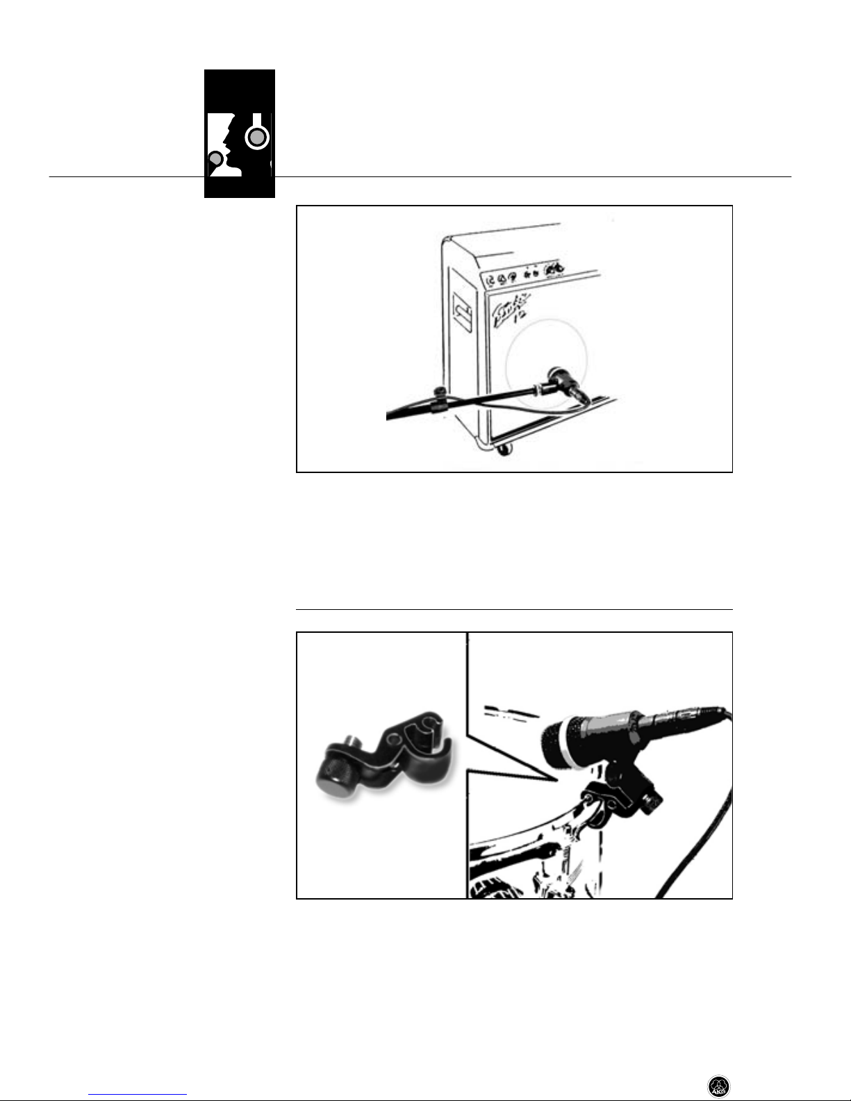
3.4 Gitarrenverstärker .........................................................................8
3.5 Tom-Toms, Roto-Toms, Snare.........................................................8
3.6 Bongos, Congas,Timbales .............................................................9
4 Reinigung..............................................................................................10
5 Fehlerbehebung....................................................................................11
6 Technische Daten..................................................................................12
Inhaltsverzeichnis
2D 40

1.1 Sicherheits-
hinweis
1.2 Lieferumfang
1.3 Optionales
Zubehör
1.4 Besondere
Merkmale
• Überprüfen Sie bitte, ob das Gerät, an das Sie das Mi-
krofon anschließen möchten, den gültigen Sicher-
heitsbestimmungen entspricht und mit einer Sicher-
heitserdung versehen ist.
• Kontrollieren Sie bitte, ob die Verpackung alle oben ange-
führten Teile enthält. Falls etwas fehlt, wenden Sie sich bitte
an Ihren AKG-Händler.
• Optionales Zubehör finden Sie im aktuellen AKG-Kata-
log/Folder oder auf www.akg.com. Ihr Händler berät Sie
gerne.
• Frequenzgang speziell für Instrumentalübertragung ausge-
legt.
• Integrierter schwenkbarer Stativanschluss zur einfachen
Montage auf Mikrofonstativen.
• Klemmhalterung H 440 erlaubt die direkte Montage an
Tom-Toms und ähnlichen Schlaginstrumenten.
• Integrierter Windschutz zur wirkungsvollen Unterdrückung
von Blas- und Windgeräuschen.
• Hohe Rückkopplungssicherheit durch frequenzunabhän-
gige nierenförmige Richtcharakteristik.
1 Sicherheitshinweis/Beschreibung
D 40 3
L
!
1 D 40 1 H 440 1 Etui

1.5 Kurzbeschreibung Das D 40 ist ein dynamisches Richtmikrofon (Druckgradienten-
empfänger). Es wurde speziell als Instrumentalmikrofon für den
harten Bühneneinsatz entwickelt. Der integrierte Stativan-
schluss besitzt einen Schwenkbereich von ca. 135° zur einfa-
chen, exakten und sicheren Ausrichtung des Mikrofons. Die
mitgelieferte Klemmhalterung H 440 erlaubt Ihnen, das Mikro-
fon direkt am Spannring von Tom-Toms, Snare, Roto-Toms
usw. anzuklemmen. Durch seine nierenförmige, frequenzunab-
hängige Richtcharakteristik ist das D 40 besonders unempfind-
lich gegen Rückkopplungen. Zum Schutz des Wandlersystems
vor Beschädigungen besitzt das D 40 einen stabilen inneren
Stützkorb. Das massive Metallgehäuse und der Außengrill aus
Stahldrahtgitter schützen das System zusätzlich. Der Aussen-
grill dient zusammen mit dem darunterliegenden Spezialge-
webe als Windschutz, der Blasgeräusche sowie Windgeräusche
auf Open-Air-Bühnen zuverlässig ausschaltet.
1 Beschreibung
4D 40

Das Mikrofon besitzt einen symmetrischen Ausgang mit 3-poli-
gem XLR-Stecker:
Stift 1 = Masse
Stift 2 = Tonader (inphase)
Stift 3 = Tonader
Sie können das Mikrofon sowohl an symmetrische als auch
asymmetrische Mikrofoneingänge anschließen.
• Wenn Sie das Mikrofon an einen symmetrischen Mikrofon-
eingang (XLR-Buchse) anschließen wollen, verwenden Sie
ein handelsübliches XLR-Kabel.
• Wenn Sie das Mikrofon an einen asymmetrischen Mikro-
foneingang (6,3 mm-Klinkenbuchse) anschließen wollen,
verwenden Sie ein Kabel mit XLR-Kupplung und 6,3 mm-
Mono-Klinkenstecker.
Bitte beachten Sie, dass asymmetrische Kabel Einstreuun-
gen aus Magnetfeldern (von Netz- und Lichtkabeln, Elektro-
motoren usw.) wie eine Antenne aufnehmen können. Bei
Kabeln, die länger als 5 m sind, kann dies zu Brumm- und
ähnlichen Störgeräuschen führen.
2 Anschluss
D 40 5

3.1 Einleitung
3.2 Saxophon
Abb. 1: Mikrofon-
aufstellung für
Saxophon
Siehe Abb. 1.
Um den ”richtigen” Sound zu finden, müssen Sie in jedem Fall
mit der Mikrofonaufstellung experimentieren. Hinweise dazu
finden Sie in den folgenden Kapiteln.
Beachten Sie, dass bei geringen Abständen zwischen Instru-
ment und Mikrofon die Bässe stärker betont werden (”Nahef-
fekt”).
Wenn Sie das Klappengeräusch als charakteristisch für den Sa-
xophonklang oder das Musikstück empfinden, richten Sie das
Mikrofon auf die Mitte des Instruments.
Erscheinen Ihnen die Klappengeräusche jedoch als störend,
richten Sie das Mikrofon auf den vorderen äusseren Rand des
Schallbechers.
Wenn Sie das Mikrofon in den Schallbecher hinein zeigen las-
sen, werden Sie einen hohen Anteil an Luftgeräuschen erhal-
ten.
Der optimale Mikrofonabstand beträgt 20 bis 30 cm.
Auf der Bühne müssen Sie eventuell näher zum Mikrofon gehen
(bis 5 cm), um Rückkopplungen und Übersprechen von anderen
Instrumenten zu vermeiden. Achten Sie in diesem Fall beson-
ders darauf, nicht direkt in das Mikrofon zu blasen.
3 Anwendung
6D 40

3.3 Trompete
Abb. 2: Mikrofon-
aufstellung für Trompete
Siehe Abb. 2.
Die Trompete erzeugt Schalldruckpegel von bis zu 130 dB. Um
Verzerrungen durch Übersteuerung zu vermeiden, richten Sie
das Mikrofon auf den unteren Rand des Schallbechers aus.
Der optimale Mikrofonabstand beträgt 30 bis 50 cm.
Auf der Bühne müssen Sie eventuell näher zum Mikrofon gehen
(bis 5 cm), um Rückkopplungen und Übersprechen von anderen
Instrumenten zu vermeiden. Achten Sie in diesem Fall beson-
ders darauf, nicht direkt in das Mikrofon zu blasen.
Sollte das Mikrofon zuviel Luftgeräusche übertragen, verwen-
den Sie einen zusätzlichen Windschutz, z.B. W 880 von AKG
(optional).
3 Anwendung
D 40 7

3.4 Gitarrenverstärker
Abb. 3: Mikrofon-
aufstellung für
Gitarrenverstärker
Siehe Abb. 3.
3.5 Tom-Toms,
Roto-Toms, Snare
Abb. 4: Mikrofon am
Tom-Tom befestigen
Siehe Abb. 4.
Lautsprecher strahlen die hohen Frequenzen sehr stark gebün-
delt aus.
Stellen Sie das Mikrofon in einer Entfernung von 5 bis 15 cm vor
der Lautsprechermembran auf und richten Sie es auf den Mit-
telpunkt der Membran aus.
1. Um zu langes Nachschwingen des Schlagfells zu verhin-
dern, befestigen Sie einen Filzstreifen oder ein Papierta-
schentuch mit Klebeband seitlich auf dem Schlagfell.
2. Schrauben Sie die mitgelieferte Klemmhalterung H 440 mit
Hilfe der unverlierbaren Rändelschraube der Klemmhalte-
rung H 440 am Stativanschluss des Mikrofons an.
3 Anwendung
8D 40

Siehe Abb. 4 auf Seite 8.
Abb. 5: Mikrofon-
ausrichtung für Tom-
Tom und Roto-Tom
Siehe Abb. 5.
3.6 Bongos, Congas,
Timbales
Abb. 6: Mikrofon-
aufstellung für Bongos
Siehe Abb. 6.
3. Hängen Sie die obere Nut der Klemmhatlerung H 440 am
oberen Rand des Spannrings ein.
4. Hängen Sie die untere Nut der Klemmhalterung H 440 an
der Unterseite des Spannrings ein.
5. Richten Sie das Mikrofon auf den äusseren Rand des
Schlagfells aus.
Stellen Sie das Mikrofon so nahe wie möglich bei den Trommeln
auf und richten Sie das Mikrofon zwischen die beiden Trom-
meln.
3 Anwendung
D 40 9

Siehe auch Kapitel 3.5.
Sie können auch zwei Mikrofone verwenden:
Stellen Sie die Mikrofone in einem Winkel von 45° zueinander
auf und richten Sie sie auf den äusseren Schlagfellrand aus.
Richten Sie sich beim Mikrofonabstand danach, wieviel oder
wie wenig Anschlaggeräusch Sie übertragen wollen. Je kürzer
der Mikrofonabstand, umso stärker das Anschlaggeräusch.
An Timbales und ähnlichen Trommeln mit Spannring können
Sie das Mikrofon auch mit Hilfe der mitgelieferten Klemmhalte-
rung H 440 direkt am Spannring befestigen.
• Reinigen Sie das Gehäuse des Mikrofons mit einem mit
Wasser befeuchteten Tuch.
3 Anwendung
10 D 40
4 Reinigung

5 Fehlerbehebung
Fehler Mögliche Ursache Abhilfe
Kein Ton. 1. Mischpult und/oder Ver-
stärker ausgeschaltet.
2. Kanal-Fader oder Sum-
menpegelregler am
Mischpult oder Laut-
stärkeregler des Ver-
stärkers steht auf Null.
3. Mikrofon nicht an
Mischpult oder Verstär-
ker angeschlossen.
4. Kabelstecker nicht rich-
tig angesteckt.
5. Kabel defekt.
1. Mischpult und/oder Ver-
stärker einschalten.
2. Kanal-Fader oder Sum-
menpegelregler am
Mischpult oder Laut-
stärkeregler des Ver-
stärkers auf gewünsch-
ten Pegel einstellen.
3. Mikrofon an Mischpult
oder Verstärker an-
schließen.
4. Kabelstecker nochmals
anstecken.
5. Kabel überprüfen und
falls nötig ersetzen.
D 40 11

6 Technische Daten
Arbeitsweise: dynamisches Druckgradientenmikrofon
Richtcharakteristik: nierenförmig
Übertragungsbereich: 50 bis 20.000 Hz
Empfindlichkeit bei 1000 Hz: 2,5 mV/Pa (- 52dBV bez. auf 1V/Pa)
Äquivalentschalldruckpegel: 18 dB(A) (DIN 45412)
Grenzschalldruck für 1% / 3% Klirrfaktor: 147 dB SPL / 156 dB SPL
Elektrische Impedanz bei 1000 Hz: ≤600 Ohm
Empfohlene Lastimpedanz: ≥2000 Ohm
Zulässige klimatische Verhätlnisse: Temperaturbereich: -10°C bis +60°C
rel. Luftfeuchtigkeit bei +20°C: 95%
Steckerart: 3-poliger Standard XLR-Stecker
Steckerbeschaltung: Stift 1: Masse
Stift 2: Tonader (inphase)
Stift 3: Tonader
Gehäusematerial: Metall
Oberfläche: dark stage blue
Abmessungen: L: 100 mm; max. ø: 80 mm; H: 42 mm
Gewicht (netto/brutto): 245 g / 380 g
Dieses Produkt entspricht den in der Konformitätserklärung angegebenen Normen. Sie können die
Frequenzgang Polardiagramm
12 D 40

Page
1Precaution/Description..........................................................................14
1.1 Precaution..................................................................................14
1.2 Packing List ................................................................................14
1.3 Optional Accessories ...................................................................14
1.4 Features.....................................................................................14
1.5 Brief Description..........................................................................15
2 Interfacing ............................................................................................16
3 Anwendung...........................................................................................17
3.1 Introduction ................................................................................17
3.2 Saxophone..................................................................................17
3.3 Trumpet......................................................................................18
3.4 Guitar Amp .................................................................................19
3.5 Tom-toms, Roto-toms, Snare Drum...............................................19
3.6 Bongos, Congas,Timbales ...........................................................20
4 Cleaning................................................................................................21
5 Troubleshooting ....................................................................................22
6 Specifications .......................................................................................23
Table of Contents
D 40 13

1 Precaution/Description
1.1 Precaution
1.2 Packing List
1.3 Optional
Accessories
1.4 Features
1.5 Brief Description
• Please make sure that the piece of equipment your mi-
crophone will be connected to fulfills the safety regu-
lations in force in your country and is fitted with a
ground lead.
• Check that the packaging contains all of the components
listed above. Should anything be missing, please contact
your AKG dealer.
• For optional accessories, refer to the current AKG catalog or
folder, or visit www.akg.com. Your dealer will be glad to
help.
• Frequency response tailored to instrument miking.
• Integrated swivel stand adapter for easy mounting on a mi-
crophone stand.
• H 440 bracket for direct mounting on a drum shell.
• Built-in windscreen/pop filter for effective suppression of
pop and breath noise.
• Frequency-independent cardioid polar response for high
gain before feedback.
The D 40 is a unidirectional (pressure gradient) dynamic micro-
phone. It has been designed primarily as an instrument micro-
phone for rough stage use. The integrated stand adapter pro-
vides a swivel range of approximately 135 degrees for easy,
precise, and reliable microphone alignment. The supplied
H 440 bracket allows you to clamp the microphone directly on
14 D 40
L
!
1 D 40 1 H 440 1 protective bag

1 Description
the top hoop of a tom-tom, snare drum, roto-tom, etc. The fre-
quency independent cardioid pickup pattern of the D 40 en-
sures high gain before feedback.The D 40 is fitted with a shock
absorbing inner grille that protects the transducer against dam-
age. The heavy-duty metal body and wire-mesh outer grille pro-
vide additional protection for the transducer system. The outer
grille and a layer of special fabric beneath it form a very effec-
tive windscreen that will suppress blowing and wind noise on
open-air stages.
D 40 15

The microphone provides a balanced output on a 3-pin male
XLR connector:
Pin 1: ground
Pin 2: hot
Pin 3: return
You can connect the microphone either to a balanced or an un-
balanced microphone input.
• To connect the microphone to a balanced input (XLR con-
nector), use a commercial XLR cable.
• To connect the microphone to an unbalanced microphone
input (1/4" jack), use a cable with a female XLR connector
and a 1/4" TS jack plug.
Please note that unbalanced cables may pick up interfer-
ence from stray magnetic fields near power or lighting ca-
bles, electric motors, etc. like an antenna. This may cause
hum or similar noise when you use a cable that is longer
than 16 feet (5 m).
2 Interfacing
16 D 40

3.1 Introduction
3.2 Saxophone
Fig. 1: Microphone
placement for the
saxophone.
Refer to fig. 1.
The best way to get the “right” sound is to experiment with mi-
crophone placement.The following sections contain useful sug-
gestions.
Please note that moving the microphone closer to the instru-
ment will boost the bass range. (This is known as “proximity ef-
fect”.)
If you consider the noise produced by the keys as characteristic
of the saxophone sound or the song, point the microphone at
the middle of the instrument.
However, if you want no key noise, direct the microphone to-
ward the front outer rim of the bell.
If you aim the microphone into the bell, you will get a high
amount of wind noise.
Optimum working distance is 8 to 12 inches.
On stage, you may have to move as close as
2 inches to the microphone in order to avoid getting feedback or
spillover from other instruments. In this situation, make sure not
to blow right into the microphone.
3 Using Your Microphone
D 40 17

3.3 Trumpet
Fig. 2: Microphone
placement
for the trumpet.
Refer to fig. 2. The trumpet can put out sound pressure levels up to 130 dB. In
order to prevent overload distortion aim, the microphone at the
lower rim of the bell.
Optimum working distance is 12 to 20 inches.
On stage, you may have to move as close as
2 inches to the microphone in order to avoid getting feedback or
spillover from other instruments. In this situation, make sure not
to blow right into the microphone.
If you get too much blowing noise, use an extra windscreen,
e.g., the optional W 880 from AKG.
3 Using Your Microphone
18 D 40

3 Using Your Microphone
Loudspeakers radiate high frequencies within a very narrow an-
gle.
Place the microphone about 2 to 6 inches in front of the loud-
speaker diaphragm and aim the microphone at the center of the
diaphragm.
1. To prevent the top head from ringing excessively, tape a
strip of felt or a piece of tissue paper to the skin in an off-
center position.
2. Screw the supplied H 440 bracket to the stand adapter on
the microphone using the captive knurled-head screw on
the H 440 bracket.
3.4 Guitar Amp
Fig. 3: Microphone
placement for a guitar
amp.
Refer to fig. 3.
3.5 Tom-toms, Roto-
toms, Snare Drum
Fig. 4: Mounting the
microphone on a tom-
tom.
Refer to fig. 4.
D 40 19

Refer to fig. 4
on page 19.
Fig. 5: Aligning the mi-
crophone with a tom-
tom or roto tom.
Refer to fig. 5.
3.6 Bongos, Congas,
Timbales
Fig. 6: Microphone
placement for bongos.
Refer to fig. 6.
3 Using Your Microphone
3. Engage the top groove of the H 440 bracket in the top hoop
from above.
4. Engage the lower arm of the H 440 bracket in the underside
of the top hoop.
5. Align the microphone with the perimeter of the top head.
Place the microphone as close as possible to the drums, aiming
it between the two drums.
Alternatively, you could use two microphones:
Set the microphones up in a “V” forming an angle of about 45
20 D 40
Other manuals for D 40
3
Table of contents
Languages:
Other AKG Microphone manuals