AKG C 542 BL User manual

C 542 BL
Bedienungshinweise . . . . . . . . . . . . . . . . . . S. 2
Bitte vor Inbetriebnahme des Gerätes lesen!
User Instructions . . . . . . . . . . . . . . . . . . . . p. 10
Please read the manual before using the equipment!
Mode d’emploi . . . . . . . . . . . . . . . . . . . . . . p. 18
Veuillez lire cette notice avant d’utiliser le système!
Istruzioni per l’uso . . . . . . . . . . . . . . . . . . . p. 26
Prima di utilizzare l’apparecchio, leggere il manuale!
Modo de empleo . . . . . . . . . . . . . . . . . . . . p. 34
Antes de utilizar el equipo, sírvase leer el manual!
Instruções de uso . . . . . . . . . . . . . . . . . . . p. 42
Favor leia este manual antes de usar o equipamen
to!

1 Sicherheitshinweis/Beschreibung
1.1 Sicherheitshinweis
Überprüfen Sie bitte, ob das Gerät, an das Sie das
Mikrofon anschließen möchten, den gültigen Sicher-
heitsbestimmungen entspricht und mit einer Sicher-
heitserdung versehen ist.
1.2 Lieferumfang
• C 542 BL
• Anschlusskabel / Phantomspeiseadapter
• Klebemasse
Kontrollieren Sie bitte, ob die Verpackung alle oben
angeführten Teile enthält. Falls etwas fehlt, wenden Sie
sich bitte an Ihren AKG-Händler.
1.3 Optionales Zubehör
• MK 9/10
•B18
1.4 Besondere Merkmale
• Robuste Mechanik
• Geringes Eigenrauschen
• Geringer Strombedarf
• Hohe Betriebssicherheit
• Trafolose Ausgangsstufe
• Speisung durch jede Phantomspeiseeinrichtung
nach DIN 45 596 / IEC 268-15
• Eingebautes, schaltbares Bassfilter mit
Einsatzpunkt des Filters bei 150 Hz
(12 dB/Oktave)
1.5 Kurzbeschreibung
Das C 542 BL ist ein Grenzflächenmikrofon. Die
Mikrofonkapsel ist bündig in eine flache Scheibe ein-
gebaut. Wenn das Mikrofon auf einer akustisch reflek-
tierenden Fläche (Grenzfläche) montiert wird, ist die
Einspracheöffnung auf die Schallquelle gerichtet und
kommt praktisch in einer Ebene mit der akustisch
reflektierenden Fläche zu liegen. Diese Methode ver-
hindert Kammfiltereffekte oder andere Interferenzen,
die sonst auftreten können, wenn Mikrofone in die Nähe
von reflektierenden Oberflächen gebracht werden.
Die Empfindlichkeit und der Frequenzverlauf des
Mikrofons hängt hauptsächlich von der Platzierung
2

der Scheibe ab. Je größer die verwendete Grenzfläche
ist, desto gleichmäßiger wird der resultierende Fre-
quenzverlauf sein und desto tiefer in den Bassbereich
wird das Mikrofon aufnehmen.
Dieses Mikrofon hat eine etwa halbkugelförmige
Richtwirkung, ist also nur vor der verwendeten Grenz-
fläche empfindlich für Schallereignisse. Dies wird auch
in vielen publizierten Arbeiten und Artikeln über diese
Art von Mikrofonen beschrieben.
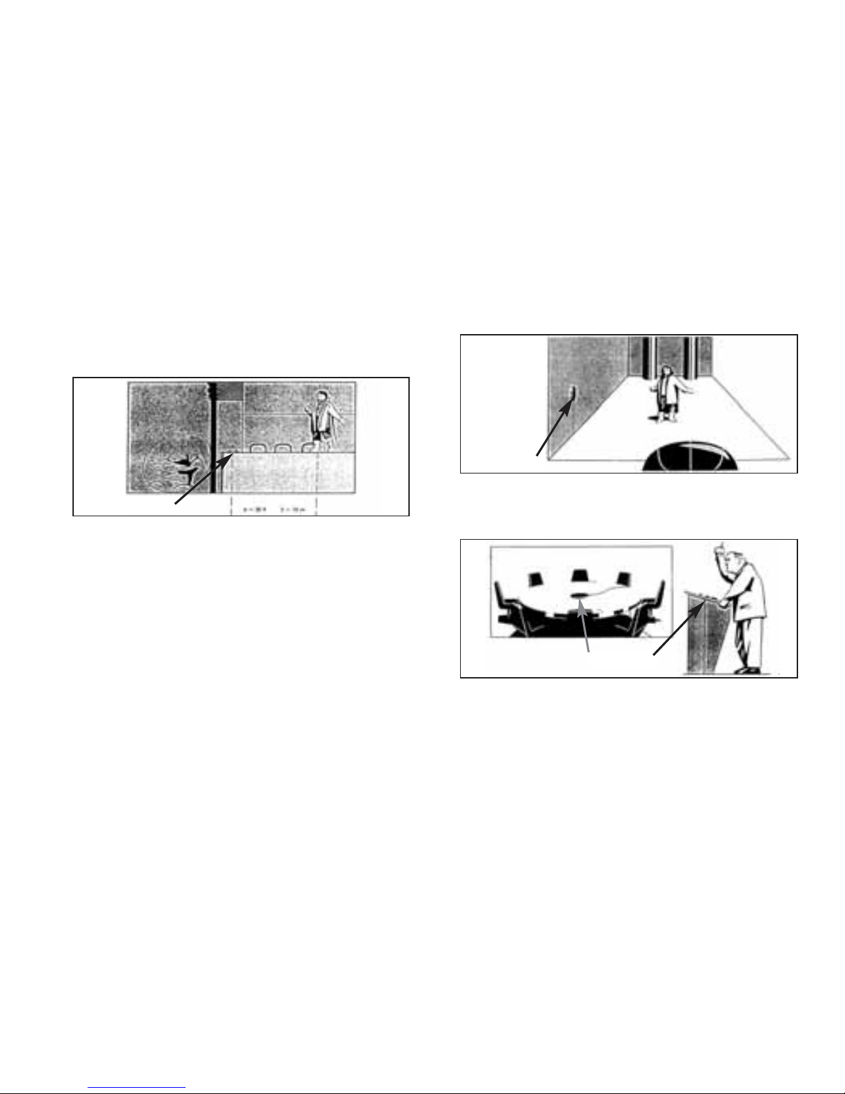
Die Empfindlichkeit ist etwa 6 dB höher als die her-
kömmlicher Kugelmikrofone, wenn das Mikrofon auf
eine große und schallharte Oberfläche (Grenzfläche)
gelegt oder montiert wird. Diese Flächen können Holz-
oder Steinböden, Wände aus ähnlichem Material,
Decken oder größere Flächen von Instrumenten, z. B.
Klavierdeckel, sein. Die Empfindlichkeitserhöhung
bewirkt auch eine Verbesserung des Geräusch-
abstandes im gleichen Maße. Das verwendete Kugel-
mikrofon nach dem Druckempfänger-Prinzip hat
weiters den Vorteil, dass es wesentlich unempfind-
licher gegen Trittschall und Windgeräusche ist als
Richtmikrofone.
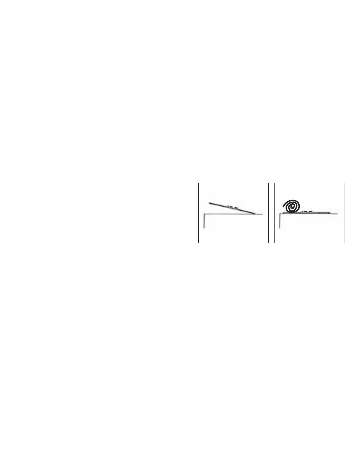
Die Gummifüßchen, eventuell in Verbindung mit der
beiliegenden Klebemasse, verhindern Reststörungen
von vibrierenden Böden oder Wänden.
Die am Mikrofon einschaltbare Bassabschwächung
hilft zusätzlich, Verzerrungen bei tiefsten Frequenzen
hintanzuhalten, die z.B. durch Rumpel- oder Wind-
geräusche auftreten können. Die Steilheit des Filters
beträgt ca. 12 dB/Oktave, die Eckfrequenz (-3 dB
Punkt) liegt bei 150 Hz.
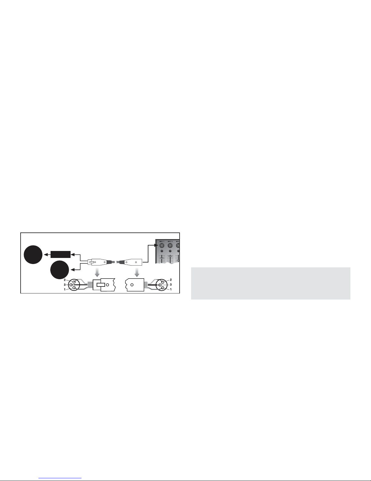
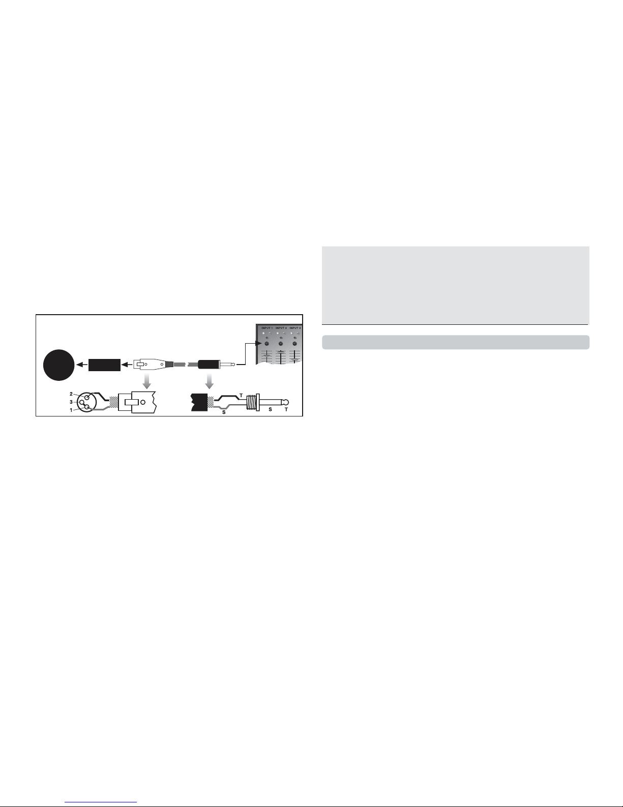
Der Mikrofonausgang ist niederohmig und elektro-
nisch symmetriert. Sie können das Mikrofon sowohl
an symmetrische Eingänge mit oder ohne Phantom-
speisung als auch an unsymmetrische Eingänge
anschließen. Zum Betrieb des Mikrofons an symmetri-
schen Eingängen ohne Phantomspeisung oder
unsymmetrischen Eingängen benötigen Sie ein Phan-
tomspeisegerät von AKG, z.B. das B 18.
2 Anschluss
2.1 Allgemeines
Das C 542 BL ist ein Kondensatormikrofon und benö-
tigt daher eine Stromversorgung.
3

Das Mikrofon besitzt einen symmetrischen Ausgang
mit 3-poligem XLR-Stecker:
Stift 1 = Masse
Stift 2 = Tonader (inphase)
Stift 3 = Tonader
Sie können das Mikrofon sowohl an symmetrische
Mikrofoneingänge mit oder ohne Phantomspeisung
als auch an asymmetrische Mikrofoneingänge an-
schließen.
2.2 Eingang mit Phantomspeisung
Siehe Abb. 1.
1. Schließen Sie das Mikrofon mit einem XLR-
Mikrofonkabel (z.B. dem optionalen MK 9/10 von
AKG) an einen symmetrischen XLR-Mikrofon-
eingang mit Phantomspeisung an.
2. Schalten Sie die Phantomspeisung ein. (Lesen Sie
dazu in der Betriebsanleitung des jeweiligen Ge-
rätes nach.)
2.3 Eingang ohne Phantomspeisung
Siehe Abb. 1.
• Wenn Ihr Mischpult keine Phantomspeisung be-
sitzt, schalten Sie zwischen Mikrofon und Misch-
pulteingang ein AKG-Phantomspeisegerät (B 18 -
optional).
Wichtig!
Wenn Sie andere als die von AKG empfohlenen
Speisegeräte verwenden, kann das Mikrofon
beschädigt werden und erlischt die Garantie.
4
2.2
2.3
Phantom
C 542 BL
C 542 BL
Abb. 1: Anschluss an symmetrischen Eingang

2.4 Asymmetrischer Eingang
Die Phantomspeisegeräte von AKG können Sie auch
an einen asymmetrischen Eingang anschließen.
Verwenden Sie dazu ein Kabel mit XLR-Stecker (weib-
lich) und Mono-Klinkenstecker:
1. Siehe Abb. 2. Verbinden Sie im XLR-Stecker
mittels einer Drahtbrücke Stift 1 mit Stift 3 und mit
der Abschirmung.
2. Verbinden Sie die innere Ader des Kabels mit Stift
2 des XLR-Steckers und der Spitze des Klinken-
steckers.
Hinweis:
Beachten Sie, dass asymmetrische Kabel Einstreu-
ungen aus Magnetfeldern (von Netz- und Lichtkabeln,
Elektromotoren usw.) wie eine Antenne aufnehmen
können. Bei Kabeln von mehr als 5 m Länge kann dies
zu Brumm- und ähnlichen Störgeräuschen führen.
3 Anwendung
3.1 Einleitung
Grenzflächenmikrofone sind unauffällig und einfach zu
platzieren. Deshalb eignet sich das C 542 BL beson-
ders für die Arbeit mit "mikrofonscheuen" Menschen
und Anwendungen, wo aus optisch/ästhetischen
Gründen kein Mikrofon sichtbar sein darf.
Beachten Sie bitte die folgenden Hinweise, um Ihr
Mikrofon optimal einsetzen zu können:
3.2 Allgemeine Aufnahmesituationen
• Siehe Abb. 3. Die einfachste Methode ist, das
Mikrofon etwa 2 bis 10 m vom Aufnahmeobjekt
entfernt auf den Boden zu legen. Die tatsächliche
Entfernung hängt von der physischen Ausdehnung
5
C 900 Phantom
C 542 BL
Abb. 2: Anschluss an asymmetrischen Eingang

der aufzunehmenden Schallquelle(n) und der spe-
zifischen Situation am Aufnahmeort ab.
Abb. 3: Einfachste Aufnahmemethode
• Siehe Abb. 4. Sie können auch eine in der Nähe
des Aufnahmeobjekts befindliche schallharte
Wand (keine Tapeten oder Dämmplatten) als
Grenzfläche benutzen. Diese Wand sollte mög-
lichst eben und schallreflektierend sein. Die Mikro-
fonplatte hat drei Löcher für die Montage an der
Wand oder Decke. Zur besseren Körperschall-
dämpfung empfehlen wir, die Gummifüßchen in
den Löchern zu belassen.
Abb. 4: Mikrofon an einer Grenzfläche montieren
3.3 Konferenztisch / Kirchenkanzel
Abb. 5: Platzierung des Mikrofons auf Tischen
6
C 542 BL
C 542 BL
C 542 BL

• Siehe Abb. 5. Sie können das Mikrofon auch auf
Konferenztischen oder Kirchenkanzeln völlig
unauffällig einsetzen.
3.4 Montage an Instrumenten
Da das Mikrofon sehr klein und leicht ist, können Sie
es auch direkt an Instrumenten mit ausreichend großer
Grenzfläche, z. B. am Deckel von Klavieren, Pianinos,
Cembalos oder Spinetten montieren.
Verwenden Sie dazu die mitgelieferte Klebemasse.
Diese lässt sich rückstandsfrei entfernen, eine Be-
schädigung alter oder empfindlicher Lackschichten
kann jedoch nicht ganz ausgeschlossen werden.
3.5 Richtwirkung
Die halbkugelförmige Richtcharakteristik kann zu
ungewollten Aufnahmen aus zuerst nicht berücksich-
tigten Richtungen führen.
Um solche Störgeräusche auszublenden, können Sie
z.B.
• das Mikrofon mittig auf eine Plexiglasplatte von ca.
1 x 1 m Größe montieren und die Plexiglasplatte
auf die gewünschte Schallquelle ausrichten (s.
Abb. 6), oder
• mit dickem Teppichmaterial zwischen Mikrofon
und störender Schallquelle den Störschall dämp-
fen (s. Abb. 7).
3.6 Tiefenabsenkung
Tieffrequente Rumpel- oder Windgeräusche von nor-
malerweise nicht als störend wahrgenommenen
Quellen wie Klimaanlagen, Verkehrslärm, Gebäude-
7
Abb. 6: Mikrofon auf
Plexiglasplatte montiert Abb. 7: Dickes
Teppichmaterial als
Schallabsorber

geräusche, etc. kommen bei einer Aufnahme sehr
deutlich zum Vorschein und können deshalb sehr stö-
rend wirken. Das im Phantomspeiseadapter eingebau-
te schaltbare Tiefenfilter bei 150 Hz erlaubt Ihnen,
diese "akustische Störquellen" auszublenden, ohne
den Klangcharakter des/der aufzunehmenden Instru-
ments/Stimme zu verändern. Die Steilheit des Tiefen-
filters beträgt 12 dB/Oktave (ca. 1:4) nach unten.
4 Reinigungshinweise
Alle Metalloberflächen können Sie problemlos mit
(Industrie-) Spiritus oder Alkohol reinigen.
8
5 Technische Daten
Richtcharakteristik: halbkugelförmig
Übertragungsbereich: 20 – 20.000 Hz (auf sehr großer Grenzfläche)
Empfindlichkeit: 20 mV/Pa / - 34 dBV bez. auf 1V/Pa
Elektr. Impedanz: < 600 Ohm
Empfohlene Lastimpedanz: > 2000 Ohm
Grenzschalldruck für 1% Klirrfaktor: 63 Pa / 130 dB SPL
Ersatzgeräuschpegel nach CCIR 468-2: 28 dB
Äquivalentschalldruckpegel nach IEC 60268-4 (A-bew.): 16 dB-A
Dynamikbereich: 114 dB max. (A-bew.)
Tiefenabsenkung: schaltbar auf linear und 150 Hz, 12 dB/Oktave

9
Speisespannung: 9 – 52 Volt Universalphantomspeisung
nach DIN 45 596 / IEC 268-15
Strombedarf: < 2 mA
Betriebstemperatur: -20°C bis +60°C
Relative Luftfeuchtigkeit: 99% (+20°C), 95% (+60°C)
Stecker: 3 pol. XLR-Stecker
Gehäuseoberfläche: dunkelgrau
Abmessungen: 80 mm ø x 5 (10) mm
Gewicht (netto): 56 g (ohne Kabel)
Dieses Produkt entspricht den in der Konformitätserklärung angeführten Normen. Sie können die Konformitäts-

1 Precaution/Description
1.1 Precaution
Please make sure that the piece of equipment your
microphone will be connected to fulfills the safety reg-
ulations in force in your country and is fitted with a
ground lead.
1.2 Unpacking
• C 542 BL
• Connecting cable w/phantom power adapter
• Adhesive compound
Check that the packaging contains all of the items list-
ed above. Should any item be missing, please contact
your AKG dealer.
1.3 Optional Accessories
• MK 9/10
•B18
1.4 Features
• Rugged construction
• Low self-noise
• Low current consumption
• High reliability
• Transformerless output
• Operates on any phantom power source to
DIN 45 596 / IEC 268-15
• Built-in switchable, 150 Hz, 12 dB/octave bass
cut filter
1.5 Brief Description
The C 542 BL is a boundary microphone. The trans-
ducer element is flush mounted in a thin disk. If you
mount the microphone on an acoustically reflective
boundary (wall, floor, ceiling), the sound entry will be
positioned almost in the same plane as the acousti-
cally reflective surface and will point toward the sound
source. This method prevents comb filter effects and
other interference that would normally cause problems
in microphones placed near reflective surfaces.
The sensitivity and frequency response of the micro-
phone depends on the disk position. The larger the
boundary, the smoother the resulting frequency re-
10

sponse and the more extended the microphone's bass
response.
The C 542 BL is an omnidirectional microphone that
will pick up sounds originating in front of the boundary
only. This has been described in many papers and arti-
cles about boundary microphones published over the
years.
When you place the microphone on a large acousti-
cally reflective surface (boundary), its sensitivity will be
about 6 dB higher than that of conventional omnidi-
rectional microphones. Such boundaries include wood
or stone floors, walls of similar materials, ceilings, or
large flat surfaces of certain instruments, e.g., piano
lids. This 6-dB increase in sensitivity also improves the
signal/noise ratio by the same amount. In addition, the
omnidirectional transducer (pressure microphone)
used in the C 542 BL is much less sensitive to footfall
and wind noise than unidirectional microphones are.
The rubber feet and supplied adhesive compound that
you may use to mount the microphone minimize resid-
ual noise from vibrating floors or walls.
The switchable bass cut filter in the phantom power
adapter further reduces low-end distortion caused by
footfall or wind noise, etc. The filter slope is approx.
12 dB/octave and its corner frequency (3-dB down
point) 150 Hz.
The microphone provides a low-impedance, electron-
ically balanced output. You can connect the micro-
phone both to balanced inputs with or without phan-
tom power and to unbalanced inputs. To use the
microphone with a balanced input with no phantom
power or an unbalanced input you will need an AKG
phantom power supply, e.g., the B 18.
2 Interfacing
2.1 General
The C 542 BL is a condenser microphone and there-
fore needs a power supply.
11

The microphone provides a balanced output on a 3-
pin male XLR connector:
Pin 1: ground
Pin 2: hot
Pin 3: return
You can connect the microphone either to a balanced
microphone input with or without phantom power or
an unbalanced microphone input.
2.2 Input with Phantom Power
Refer to fig. 1.
1. Use an XLR cable (e.g., the optional MK 9/10 from
AKG) to connect the microphone to a balanced
XLR input with phantom power.
2. Switch the phantom power on. (Refer to the
instruction manual of the unit to which you con-
nected your microphone.)
2.3 Input with No Phantom Power
Refer to fig. 1.
• If your mixer provides no phantom power, connect
an optional AKG phantom power supply (B 18)
between the microphone and the mixer.
Important!
Using any power supply other than those recom-
mended by AKG may damage your microphone
and will void the warranty.
2.4 Unbalanced Input
You may connect AKG phantom power supplies to
unbalanced inputs, too.
Use a cable with a female XLR connector and TS jack
plug:
12
2.2
2.3
Phantom
C 542 BL
C 542 BL
Fig. 1: Connecting to a balanced input.

1. Refer to fig. 2. On the XLR connector, use a wire
bridge to connect pin 1 to pin 3 and the cable
shield.
2. Connect the inside wire of the cable to pin 2 on the
XLR connector and the tip contact of the jack plug.
Note:
Unbalanced cables may pick up interference from
stray magnetic fields near power or lighting cables,
electric motors, etc. like an antenna. This may intro-
duce hum or similar noise when you use a cable that
is longer than 16 feet (5 m).
3 Using the Microphone
3.1 Introduction
Boundary microphones are inconspicuous and easy to
position. Therefore, the C 542 BL is an excellent
choice for working with people who tend to shy away
from microphones and applications where no micro-
phone must be visible for visual or esthetic reasons.
The following sections contain hints on how to get the
best possible results.
3.2 General Recording
Fig. 3: Easy recording technique.
13
Phantom
C 542 BL
Fig. 2: Connecting to an unbalanced input.
C 542 BL

• Refer to fig. 3. The easiest technique is to place
the microphone on the floor about 7 to 35 feet (2
to 10 m) away from the sound source. The ultimate
working distance will depend on the physical
dimensions of the sound source(s) to be recorded
and the specific situation at the recording location.
• Refer to fig. 4. Alternatively, you may use an a-
coustically reflective wall (covered with no wallpa-
per or softboard) near the sound source.
Fig. 4: Mounting the microphone on a boundary.
The wall should be as even and reflective as pos-
sible. The microphone disk has three holes for
mounting on a wall or ceiling. To ensure optimum
deadening of structure-borne noise, we recom-
mend leaving the rubber feet inside the holes.
3.3 Conference Table / Pulpit
Fig. 5: Placing the microphone on a table.
• Refer to fig. 5. The microphone will keep a very low
profile on conference tables or pulpits, too.
3.4 Mounting the Microphone on an Instrument
Since the microphone is very small and light, you can
even mount it directly on instruments with a sufficient-
ly large boundary such as the lid of a grand or upright
piano, harpsichord, or spinet.
14
C 542 BL
C 542 BL

Use the supplied adhesive compound. Although it will
leave no residues when removed from most surfaces,
there may be a minimal risk of old or delicate lacquer
coats being damaged.
3.5 Directivity
The microphone's omnidirectional (hemispherical) po-
lar pattern may cause unwanted sounds to be picked
up from unexpected directions.
To suppress these unwanted sounds, you may, for
instance,
• mount the microphone in the center of a plexiglass
panel about 3 feet square and align the plexiglass
panel with the desired sound source (see fig. 6), or
• place thick carpet between the microphone and
the unwanted sound source(s) as shown in fig. 7 to
reduce the spillover.
3.6 Bass Cut Filter
Low-frequency rumble or wind noise from sound
sources we do not normally perceive as irritating, such
as air conditioning, traffic, or structure-borne noise,
may become clearly audible and therefore definitely
irritating on a recording. The 150 Hz bass cut filter in-
tegrated in the phantom power adapter allows you to
reject this unwanted noise without changing the sound
of the instrument or voice you are recording. The filter
slope is 12 dB/octave (approx. 1:4).
15
Fig. 6: Microphone
mounted on plexiglass
panel.
Fig. 7: Using thick car-
pet to reduce spillover.

4 Cleaning
You can clean all metal surfaces with (industrial grade)
methylated spirits or alcohol.
16
5 Specifications
Polar pattern: omnidirectional (hemispherical)
Frequency range: 20 to 20,000 Hz (mounted on very large boundary)
Sensitivity: 20 mV/Pa / -34 dBV re 1 V/Pa
Electrical impedance: < 600 ohms
Recommended load impedance: > 2000 ohms
Max. SPL for 1% THD: 63 Pa / 130 dB SPL
Equivalent noise level to CCIR 468-2: 28 dB
Equivalent noise level to IEC 60268-4 (A-weighted): 16 dB-A
Dynamic range: 114 dB max. (A-weighted)
Bass cut filter: switchable to flat or 150 Hz, 12 dB/octave
Powering: 9 to 52 V phantom power to DIN 45 596/IEC 268-15
Current consumption: < 2 mA
Opeating temperature: -20°C to +60°C
Relative humidity: 99% (+20°C); 95% (+60°C)

17
Connector: 3-pin XLR
Finish: dark gray
Dimensions: 80 dia. x 5 (10) mm / 3.1 dia. x 0.2 (0.4) in.
Net weight: 56 g / 2 oz. (without cable)
This product conforms to the standards listed in the Declaration of Conformity. To order a free copy of the

1 Consigne de Sécurité/Description
1.1 Consigne de sécurité
Vérifiez si l’appareil auquel vous voulez raccorder le
microphone répond aux prescriptions relatives à la
sécurité en vigueur et s’il possède une mise à la terre
de sécurité.
1.2 Fournitures d'origine
• C 542 BL
• Câble de raccordement / Adaptateur pour alimen-
tation fantôme
• Mastic
Assurez-vous que l’emballage contient bien toutes les
pièces indiquées ci-dessus. Si ce n’est pas le cas,
contactez immédiatement votre fournisseur AKG.
1.3 Accessoires optionnels
• MK 9/10
•B18
1.4 Caractéristiques particulières
• Mécanisme robuste
• Bruit propre minime
• Faible consommation
• Grande sécurité de fonctionnement
• Etage de sortie sans trafo
• Possibilité d’utiliser toute alimentation en fantôme
selon DIN 45 596 / CEI 268-15
• Filtre coupe-bas incorporé commutable, interve-
nant à la fréquence de 150 Hz (12 dB/octave)
1.5 Brève description
Le C 542 BL est un microphone à zone de surface. La
capsule de micro est montée affleurée dans un disque
plat. Lorsque le microphone est placé sur une surface
acoustique réfléchissante, l’ouverture côté sensible
est dirigée sur la source sonore et se trouve pratique-
ment au même niveau que la surface réfléchissante.
Cette méthode empêche tout effet de "filtre en
peigne" ou autres susceptibles de se produire lors-
qu’un micro se trouve à proximité d’une surface réflé-
chissante.
La sensibilité et la réponse en fréquence du micro
dépendent principalement de l’emplacement du
disque. Plus la surface réfléchissante est grande, plus
18

la réponse en fréquence est régulière et plus impor-
tante est l’étendue du grave capté par le micro.
Ce micro a un diagramme directif approximativement
hémisphérique, il n’est donc sensible à ondes sonores
que devant la surface réfléchissante utilisée. Ce phé-
nomène est décrit dans de nombreux articles et
études publiés sur ce type de micro.
La sensibilité du micro est supérieure de 6 dB environ
à celle des micros omnidirectifs classiques lorsque le
micro est posé ou monté sur une surface réfléchis-
sante suffisamment grande et réverbérante. On peut
utiliser comme surface réfléchissante un plancher ou
une dalle de pierre, des murs en matériaux analogues,
un plafond ou une surface suffisamment grande fai-
sant partie d’un instrument de musique, p.ex. un cou-
vercle de piano. L’augmentation de la sensibilité s’ac-
compagne d’une amélioration correspondante du rap-
port signal sur bruit. Le micro omnidirectif utilisé,
conçu selon le principe du microphone à pression, a
par ailleurs l’avantage d’être beaucoup moins sensible
aux bruits de pas et de vent que les microphones uni-
directionnels.
Les pieds de caoutchouc et l’utilisation, le cas
échéant, du mastic fourni évitent les perturbations
résiduelles pouvant être dues à la vibration du sol ou
d’une cloison.
L’atténuation du grave contribue également à éviter
les distorsions à très basse fréquence dues p.ex. au
rumble ou aux bruits de vent. La pente du filtre est
approx. de 12 dB/octave, la fréquence de coupure
(-3 dB) se situe à 150 Hz.
La sortie du micro à basse impédance est équilibrée
électroniquement. Vous pouvez brancher votre micro
aussi bien sur des entrées symétriques avec ou sans
alimentation fantôme que sur des entrées asymé-
triques. Pour faire fonctionner le micro sur des entrées
symétriques sans alimentation fantôme ou sur des
entrées asymétriques, vous avez besoin d’un module
d’alimentation fantôme AKG, p.ex. le B 18.
2 Raccordement
2.1 Indications générales
Le C 542 BL est un microphone électrostatique ; il a
donc besoin d’une alimentation.
19

Le microphone possède une sortie symétrique avec
fiche XLR tripolaire :
broche 1 = masse
broche 2 = point chaud
broche 3 = point froid
Vous pouvez raccorder le microphone à volonté sur
une entrée micro symétrique avec ou sans alimenta-
tion fantôme ou bien sur une entrée asymétrique.
2.2 Entrée avec alimentation fantôme
Voir Fig. 1
1. Connectez le microphone à l’aide d’un câble de
micro XLR-XLR (p.ex. l’AKG MK 9/10 optionnel)
sur une entrée de micro symétrique type XLR avec
alimentation fantôme.
2. Mettez l’alimentation fantôme sous tension
(Veuillez vous reporter à la notice de l’équipement
utilisé).
2.3 Entrée sans alimentation fantôme
Voir Fig. 1
• Si votre table de mixage ne possède pas d’alimen-
tation fantôme, insérez une alimentation fantôme
AKG optionnelle (B 18) entre le micro et l’entrée de
la table de mixage.
Important !
L’utilisation d’alimentations autres que celles
recommandées par AKG peut provoquer des
dégâts sur le micro et entraîne la perte de la garan-
tie.
2.4 Entrée asymétrique
Vous pouvez aussi connecter les alimentations fantô-
me d’AKG sur une entrée asymétrique.
20
2.2
2.3
Phantom
C 542 BL
C 542 BL
Fig. 1 : connexion sur une entrée symétrique
Other manuals for C 542 BL
1
Table of contents
Languages:
Other AKG Microphone manuals