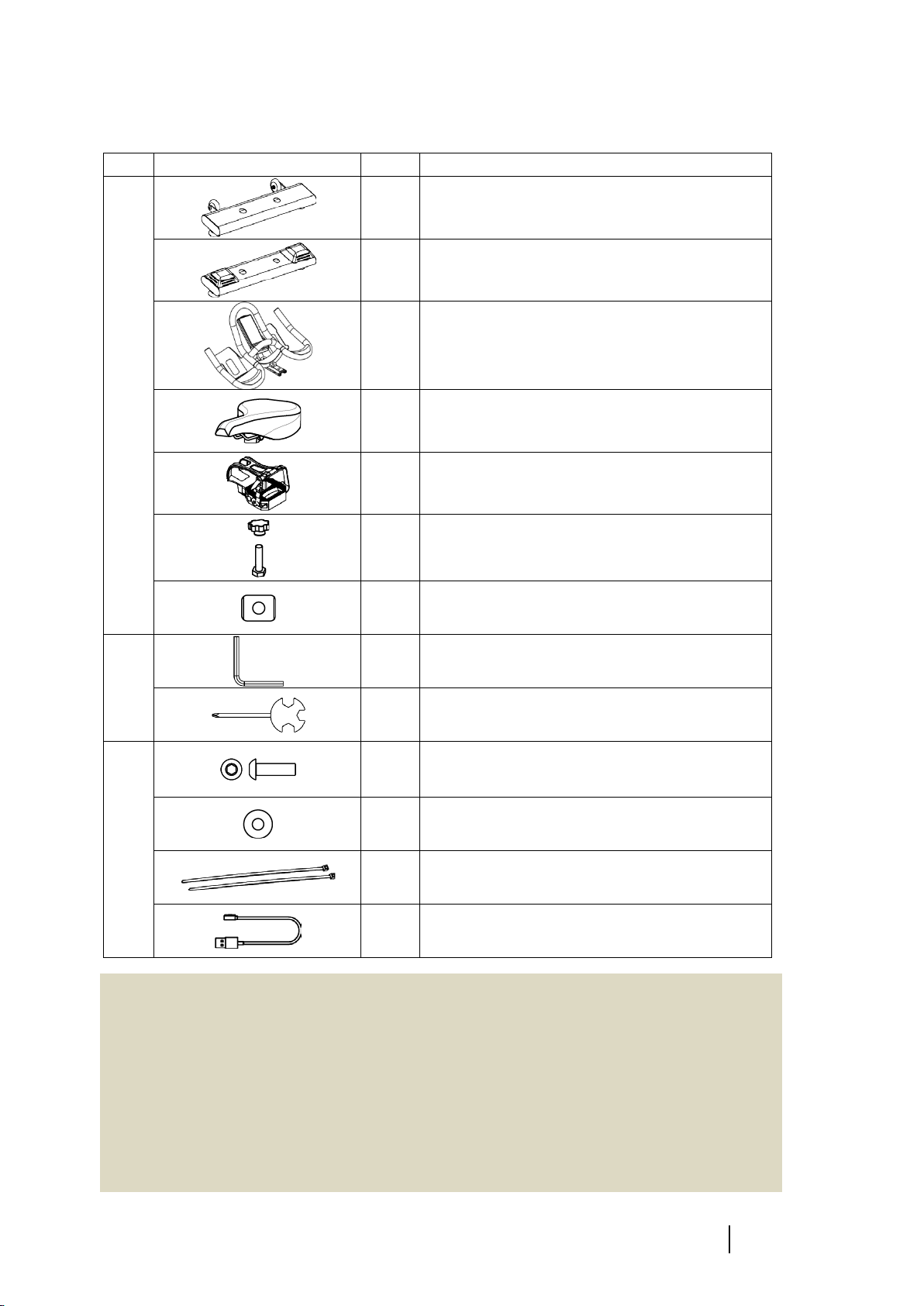
alatech AP1000 User manual

FireFlyAP1000
Training & Indoor Cycling
TFT Model Only

i FireFly Training & Indoor Cycling
Table of Contents
1Important Notice............................................................ 1
2Safety Precautions.......................................................... 1
3Assembly........................................................................ 4
3.1 Parts List ............................................................................................................6
3.2 Assemble Steps .................................................................................................8
4Preparation .................................................................. 14
4.1 Placement of the Equipment ..........................................................................14
4.2 Adjusting the Training & Indoor Cycling..........................................................15
4.3 Resistance/Brake.............................................................................................18
4.4 Calibration Resistance Level............................................................................19
4.5 Moving Guideline............................................................................................20
5The Electronic Console................................................. 21
Operation Overview....................................................................................................22
5.1 Set up Mode....................................................................................................24
5.1.1 Record .............................................................................................................24
5.1.2 Activity.............................................................................................................24
5.1.3 System .............................................................................................................24
5.1.4 User .................................................................................................................24
5.1.5 Light Setting.....................................................................................................25
5.1.6 Sensor..............................................................................................................25
5.2 Activity Mode ..................................................................................................26
5.2.1 Quick Start.......................................................................................................26
5.2.2 Start with Training Goal...................................................................................28
5.2.3 FTP Test (Functional Threshold Power Test) ...................................................29
5.3 Application and Compatibility.........................................................................30
5.4 Heart Rate Zone Indicator ...............................................................................32
5.5 FTP Zone Indicator...........................................................................................33
5.6 Watt Zone Indicator ........................................................................................35
6Maintenance ................................................................ 36
7Specification................................................................. 38
8Appendix...................................................................... 39
8.1 Exploded View.................................................................................................39
8.2 World Time Zone Table ...................................................................................41

1 FireFly Training & Indoor Cycling
1Important Notice
FireFly AP1000 Training & Indoor Cycling is referred to as “bike” or “equipment” in this
operation guide.
Please Keep the Manual in Good Condition
Please thoroughly read and follow the instructions for assembling or using the
equipment. If you have any questions please contact your local distributor or visit our
website: ATTACUSfitness.com.
For your safety, please take safety measures and follow the instructions. Keep this
manual in good condition for future reference.
The owner of the equipment has the sole responsibility ensuring that all the
instructions and safety measures are learned and followed by the users.
You can download the most up-to-date user’s guide from our
website: ATTACUSfitness.com.
2Safety Precautions
Warning!! To reduce the risk of burns, fire, electric shock,
or personal injury, please observe the following:
Please follow the instructions from the manual.
DO NOT add additional components, attachments, or accessories that have not been
recommended by the manufacturer.
Please check the components on a regular basis. Keep the components tightly
installed. Please do not use the equipment when there is any malfunction, damage, or
missing parts and contact your distributor for maintenance or for spare parts for the
damaged/missing component. Do not use the equipment before it is well-maintained.
ATTACUS is not responsible for any personal injury or death caused by faulty assembly,
self-modification/disassembly, or any other ways the user fails to follow the manual.
Improper training and/or overtraining can cause serious physical injury or death. If
you are experiencing any kinds of pain, nausea, dizziness, shortness of breath, etc.,
Stop exercising immediately and consult a doctor.
It is highly recommended for you to consult your doctor and run a full health check to
find a proper and appropriate exercise program if you are any of the following:
pregnant, having chronic health condition like hypertension and cardiovascular
diseases, smoking, over45 years old, obese, or not having proper exercise routines for
more than one year.
This equipment is not suitable for anyone who is poor in physical, sensory, or mental
capacity. Children under 13 years old are not allowed to use the equipment. Please do

Operation Guide 2
not let children or pets near within 10 inches (3 meters).
The persons with reduced physical, sensory or mental capabilities, or lack of
knowledge, and the adolescent from 13 to 19 years, or the aged over 65 should not
be on the equipment without proper and constant supervision by a potter/supervisor.
Please do not attempt improper use of the product, such as leaping onto, or standing
on the handlebar, saddle, or any parts that are not the pedals.
Please place the indoor bike in an indoor environment with a flat and stable floor. It is
highly recommended to put the bike on a shock and sound-absorbing mat to protect
the floor and enhance the quality of use.
Please keep the surrounding area clear for 2 ft (0.6meter) on all sides.
Under any circumstances, the equipment is for one person to use only. Do not have
more than one user using it simultaneously.
Maximum user weight limit: 350 lb (159 kg).
User height limit: 200 cm (5 ft 9 in to 7 ft 87 in).
Please be sure all the adjustment knobs are tightened before using.
Please adjust the handlebar, seat, resistance, and pedal straps according to your own
physical condition to prevent any discomfort and injury. When adjusting the seat and
handlebar, please hold the adjusting part with one hand to prevent the parts falling or
any danger.
Please be sure to wear proper exercise attire. Wearing loose blouse or having your
shoelaces loosen may caused injury or death when the loose parts being grind into
the machine.
Please be mindful and avoid putting any part of the body or other external object into
any open gaps, moveable and/or mechanical parts of the indoor bike. Please do not
turn the pedals with your hands.
Obtrusive parts, such as the Resistance Knob (brake), may hinder user's movement,
please beware of these parts when using the equipment.
Please maintain proper posture and body position to achieve a safe, comfortable and
effective workout. Refer to the sections 4.2 Adjusting the Training & Indoor Cycling.
This equipment does not have a freewheel. This means the momentum of the wheel
may cause the pedal to turn even when you have stopped pedaling.
Do not remove your feet from the pedal cages until the wheel and the pedals have
stopped completely. Failure to do so may result in serious injury. The still turning
pedals may trip or hit the people around and cause serious injury or death.
If you would like to stop the wheel immediately, please press the red knob.
When the bike is not being used, be sure to add on full resistance to prevent it from
spinning or causing any potential harm to the personnel around.
This equipment is for indoor use only. Please avoid keeping the equipment in places
with extreme temperature and humidity, or is dusty or susceptible to the splash of
water and fluid.

3 FireFly Training & Indoor Cycling
⚠
Warning!
Use the stationary training equipment in a supervised environment.
Please consult your physician before starting any exercise plan. Improper training or
overtraining can result in serious injury or death.
Please be sure to read through and be familiar with the instructions and cautions
from this guide. This will reduce the potential for injury and insure your safety.
If the equipment has been exposed to low temperature or humid environment, it is
highly recommended to leave it at room temperature and/or dry it before using.
Using the bike in the aforementioned circumstance might shorten the lifespan of
electronic parts.

Operation Guide 4
3Assembly
Please thoroughly read through the manual before assembling. If you have any questions,
please consult your distributor or see more information on our
website: ATTACUSfitness.com. Please have your model number and serial number ready
when you call.
Parts List:
Console
Handlebar
Bottle Holder
Handlebar Adjustment knob
pedal
Transportation Wheels
Front Stabilizer Tube
Rear Stabilizer Tube
Handlebar Horizontal
adjustment knob
Saddle Horizontal
Adjustment Knob
Resistance
Adjustment/ Brake
Saddle Vertical
Adjustment Knob
Wheel Cover
Left Maintenance
Cover
Stretching
Boards
Adjustable Levelers

5 FireFly Training & Indoor Cycling
Product information:
WARNING!
Heart rate monitoring systems may be
inaccurate. Over exercise may result in
serious injury or death. If you feel faint
stop exercising immediately.
Use the stationary training equipment
in a supervised environment.
Scan the QR Code on the
back of your device to:
Connect and pair with
the APPs.
Register the product.
Download the most
up-to-date operation
guide.
Please be sure to have your model name and serial number ready before calling the customer
service. The model name and serial number can be found on the right side near the rear end.
Model: AP1000
SN:
P
1
0
0
4

Operation Guide 6
3.1 Parts List
Image # Specification
Components
1 Front Stabilizer Tube
1 Rear Stabilizer Tube
1 Handlebar (installed)
1 Saddle
2 Pedal
2 Adjustment Knob
2 Slide Gasket
Included
Tools
1 6mm Hex Wrench or Allen Key
1 Open-ended Wrench/ Screwdriver
Tool Pack
4 Socket Button Head Cap Screw
(M10×1.5×20L)
6 Washer(Ø25ר10×2t)
2 Cable Tie
1 Console Charging Cable
⚠
Attention!
Please follow the instructions for assembly to ensure all the components are all set
and tightened. Failure to follow the correct steps may cause damage to the
equipment and make unsettling noises. Using equipment that is improperly
assembled may lead to serious injury and death.
If you have any questions or the equipment has any missing parts, please contact
your distributor or dial in the customer service number on the maintenance card.
The equipment should be assembled by at least 2 persons. DO NOT attempt to pull

7 FireFly Training & Indoor Cycling
up the bike with single arm because some parts can be heavy. Assembling alone
may lead to serious injury and damage to the equipment when parts are dropped.
When the product arrives, please carry it carefully. Place the carton box on a flat
surface. Do not open the box when it is placed on its side to prevent parts from
falling out.
It is highly recommended for you to place a mat on the floor to protect your
flooring.
Please unpack and assemble the product on a set location to reduce unnecessary
moving.
Please be careful when removing the cable ties on the package exterior. The cable
ties outside the box may produce strong momentum; it might bounce off and snap
on the people around if not cautiously removed.
When unpacked, please place all the components in a clear area to enhance the
assembling process.
Please follow the proper instructions. When performing each step, please be sure
all the screws and bolts are in place and partially tighten. Please tighten all the
screws and bolts when all are in place.
Please be sure all the loose components are fixed and tightened. Please do not
reduce the number of screws and/or bolts used to prevent unwanted danger and
harm.
Some parts are pre-lubricated to help with the assembly. Do not wipe off the
grease. If you have encountered difficulty when assembling, you can apply some
grease when assembling. It is recommended to use lithium-based grease.
Unauthorized personnel are prohibited to remove the maintenance covers.
Before the assembly is completed, do not throw away the packaging material.

Operation Guide 8
3.2 Assemble Steps
STEP 1 Assemble the Front Stabilizer Tube
Parts in
letters Parts Images Specification # of part
used
A 6mm Hex Wrench/Allen Key 1
B
Socket Button Head Cap Screw
(M10×1.5×20L)2
C Spring Washer(Ø25ר10×2t)2
D
Front Stabilizer Tube 1
C
B
A
D

9 FireFly Training & Indoor Cycling
STEP 2 Assemble the Rear Stabilizer Tube
Parts in
letters Parts Images Specification # of part
used
A 6mm Hex Wrench/Allen Key 1
B
Socket Button Head Cap Screw
(M10×1.5×20L)2
C Spring Washer(Ø25ר10×2t)2
D
Rear Stabilizer Tube 1
A
D
C
B

Operation Guide 10
STEP 3
Assemble the Handlebar
1) Please use Athe screwdriver to remove Fscrew and end cap as
shown in the picture below.
2) Place DSlide Gasket into the slide bar.
3) Place the EHex Bolt from the bottom to top through the
components and the DSlide Gasket, screw the CAdjustment Knob
to the EHex Bolt.
4) Please put the parts removed in STEP 1, the screw and end cap,
back on and tighten.
Parts in
letters Parts Images Specification # of part
used
A
Open-ended Wrench/ Screwdriver 1
B
Handlebar (console installed) 1
C Adjustment Knob 1
D Slide Gasket 1
E Hex Bolt(M10×1.5×40L)1
Partial enlarged view
C
B
F A
C
D
E

11 FireFly Training & Indoor Cycling
STEP 4
①
Assemble Quick-release L Knob
1) Please use AScrewdriver to remove Fscrew and end cap as shown
in the picture below.
2) Place DSlide Gasket into the slide bar.
3) Place the EHex Bolt from the bottom to top through the
components and the DSlide Gasket, screw the CAdjustment Knob
to the EHex Bolt.
4) Please put the parts removed in STEP 1, the screw and end cap
back on and tighten.
②
Use A the Open-ended Wrench to
tighten the saddle
Parts in
letters Parts Images Specification # of part
used
A
Open-ended Wrench/ Screwdriver 1
B Saddle 1
C Adjustment Knob 1
D Slide Gasket 1
E Hex Bolt(M10×1.5×40L)1
B
A
Partial enlarged view
E
C
D
A
F

Operation Guide 12
STEP 5
Assemble the pedals
1) Please note that both pedals are reverse-threaded. Put the Bleft
pedal into the left crank-hole and screw it in the counterclockwise
manner.
2) Align the C right pedal into the right crank hole; in the clockwise
manner, crank it tight with Aopen-ended wrench into the thread.
3) Please be sure that both pedals are tightened. Having loose pedals
during activity will cause serious injury or death to the user.
Parts in
letters Parts Images Specification # of part
used
A
Open-ended Wrench/ Screwdriver 1
B
Left pedal 1
C
Right Pedal 1
B
A
C

13 FireFly Training & Indoor Cycling
STEP 6
Complete the assembly
1) Insert the power cord into the jack on the back of the console.
2) Please use Acable tie to tie the cable with the console stand to
avoid damage or personnel injury caused by accidentally pulling the
cord or hindrance of movement.
Parts in
letters Parts Images Specification # of part
used
A Cable tie 1
A
Power cord

Operation Guide 14
4Preparation
Riding a spin bike is considered as intense aerobic exercise. To prevent possible injury,
please evaluate your physical condition and be sure to do the following:
1) Please warm up properly before the workout.
2) Please stay focused during workout and maintain the correct posture. If you are using
a tablet or other devices please ensure your own safety and be mindful of your
posture to avoid any danger or injury.
3) Please train with guidance of fitness professionals and train step by step with proper
process.
4) Please adjust your training time and intensity according to your own physical
condition. Overtraining will cause chronic fatigue and/ or severe physical injury.
5) If you are experiencing any kinds of pain, nausea, dizziness, shortness of breath, etc.,
Stop exercising immediately and consult a doctor if the symptoms persist.
6) After workout please properly stretch and massage your muscles to reduce physical
fatigue.
4.1 Placement of the Equipment
Please place the equipment on a level ground and avoid direct sunlight. Do not place it
outdoors, in the garage, open yard, humid, and/or ventilated places. For safety purposes,
please keep the equipment’s surrounding clear for 2 ft (0.6 Meters) on all four sides.

15 FireFly Training & Indoor Cycling
4.2 Adjusting the Training & Indoor Cycling
For your comfort and workout efficiency, please adjust the handlebar and saddle in
accordance to your height.
STEP 1 Adjusting the Saddle
1) Turn the adjustment knob counterclockwise to loosen and pull the knob outwardly.
2) When you have pulled the knob, you can then pull up or adjust the saddle tube. Set
the saddle at the in the height of your upper hip. Once all set, in the clockwise
manner tightened the knob.
3) For beginners, if you are not used to the height of the saddle, you can adjust it by 1-2
scales lower.
Maintain a natural spine
The hips remain stabilized
Knee slightly bent
Elbow slightly bent
Naturally hold the
handlebar
The front knee and
foot should be on one
vertical line
Equal force from both
legs

Operation Guide 16
STEP 2 Adjusting the Handlebar and Saddle
1) Turn the Adjustment Knob counterclockwise to release and push the handlebar and
saddle to your preferred horizontal position.
2) The ideal distance between the saddle and handlebar is the length of your elbow to
the tip of the middle finger; you can measure it by putting your elbow on the tip of
the saddle horizontally to evaluate the distance. Once you are all set, you can turn
the Adjustment Knob to the left and tightened it.
STEP 3 Adjusting Handlebar Height
1)
Turn the knob counterclockwise, and pulled the knob outwardly.
2) As the knob is pulled, raise the handlebar to the equal height of the saddle. Once
done, turn in a clockwise manner to tighten the knob.
3) When on the saddle, hold the handlebar with both hands.
4) You can also pull the handlebar slightly higher than the saddle and ride in a more
comfortable posture. Once you are used to the exercise, you can then adjust the
height to the same as the saddle.

17 FireFly Training & Indoor Cycling
STEP 4 Tightened and Release of the Pedal
Straps
Start an activity End an activity
1)
Buckle up the strap.( A )
2) Place your foot into the pedal cage.( B )
3) Pull up on the Pedal Strap to tighten the
Pedal Cage, snug to fit.( B )
1)
Slow down or press the emergency
brake to stop.
2) Once the wheel and the pedals have
stopped entirely, push down on the
buckle to release the pedal strap.( C )
A B C
Other manuals for AP1000
1
Table of contents
Other alatech Fitness Equipment manuals