Alcor Micro AU9216 Product manual

AU9216
USB Hub Controller
Technical Reference Manual
Revision 1.01
© 1998 Alcor Micro Inc.
All rights reserved

Copyright Notice
Copyright 1998
Alcor Micro Inc.
Allrights Reserved.
TrademarkAcknowledgements
The companyand product names mentioned inthis document maybe the trademarks or registered trademarks oftheir manufacturers.
Disclaimer
Alcor Micro Inc. reserves the right to change this product withoutnotice.
Alcor Micro Inc. makes no warrantyfor the use ofits products and bears no responsibilityfor anyerrors whichappear inthis
document. Specifications are subject to change withoutnotice.
Contact Information
USA Headquarters Los Angeles
Alcor Micro, Inc. Alcor Micro, Inc.
155-AMoffett Park Drive, Suite 240 9400 SeventhSt., Bldg.A2
Sunnyvale CA, 94089 Rancho Cucamonga, CA91730
Phone:(408) 541-9700 Phone:(909) 483-9900
Fax:(408) 541-0378 Fax:(909) 944-0464
Taiwan
Alcor Micro Inc. Taiwan
7F, No 279, Sec. 4, Hsin-I Road,
Taipei, Taiwan R.O.C.
Phone:886-22-325-9512
Fax:886-22-702-6030

TABLE OF CONTENTS i
Table of Contents
1.0 Introduction
................................
................................
................................
......
1
1.1. Description .............................................................................................................1
1.2. Features .................................................................................................................1
2.0 Application Block Diagram
................................
................................
.............
3
3.0 Pin Assignment
................................
................................
................................
5
4.0 System Architectureand Reference Design
................................
.................
17
4.1. AU9216 Block Diagram.........................................................................................17
4.2. Sample Schematics.................................................................................................18
5.0 Electrical Characteristics
................................
................................
................
21
5.1. Maximum Ratings..................................................................................................21
5.2. Recommended Operating Conditions.....................................................................21
5.3. Crystal Oscillator Circuit Setup for Characterization.............................................22
5.4. USB Transceiver Characteristics............................................................................22
5.5. ESD Test Results....................................................................................................27
5.6. Latch-Up Test Results............................................................................................28
6.0 Mechanical Information
................................
................................
...................
31

This Page Intentionally Left Blank

INTRODUCTION 1
1.0 Introduction
1.1. Description
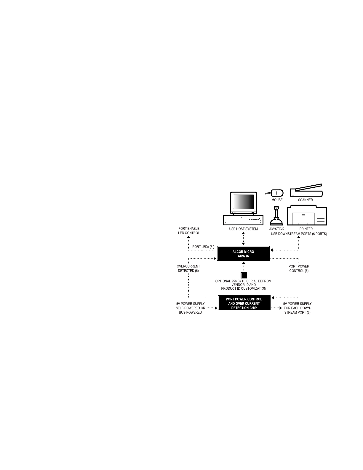
The AU9216 is an integrated single chip USB hub controller. It is designed to support the
emerging industry Universal Serial Bus (USB) standard. The AU9216 can support up to six
USB downstream ports. Each downstream port supports separated enable LED, power control
and over-current sensing. Single chip integration makes the AU9216 the most cost effective
stand-alone USB hub solution available in the market. USB vendor ID and Device ID can be
customized via external EEPROM. Downstream ports can be used to connect various USB
peripheral devices, such as USB printers, modems, scanners, cameras, mice, or joysticks, to
the system without adding external glue logic.
1.2. Features
•Fully compliant with the Universal Serial Bus Specification, version 1.0
•USB hub design is compliant with Universal Serial Bus Hub Specification, revision 1.1
•Single chip integrated USB hub controller with embedded proprietary processor
•Supports six bus-powered or self-powered downstream ports
•Supports individual port power control, LED and over-current detection
•USB vendor and device ID can be customized via external EEPROM
•Built-in default vendor ID provides cost saving if customization is not required
•Built-in 3.3v voltage regulator allows single +5V operating voltage drawing directly from
USB bus. This results in reduced overall system cost.
•Runs at 12Mhz frequency
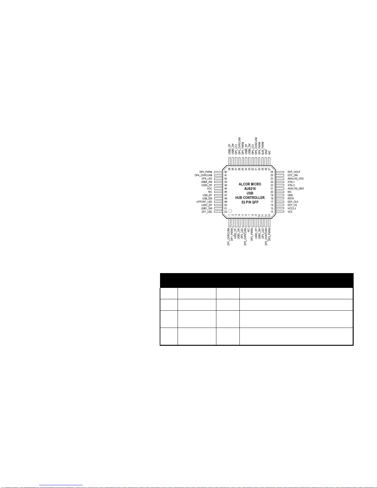
•Available in 48-pin DIP and 52-pin QFP

2INTRODUCTION
This Page Intentionally Left Blank

APPLICATION BLOCK DIAGRAM 3
2.0 Application Block Diagram
The AU9216 is a single chip 6-port USB hub controller. The upstream port is connected to
the USB system. The downstream ports can be used for a mouse, joystick, scanner, printer or
other device.

4APPLICATION BLOCK DIAGRAM
This Page Intentionally Left Blank

PIN ASSIGNMENT 5
3.0 Pin Assignment
The AU9216 is packaged both as a 52-pin quad flat pack (QFP) and as a 48-pin dual inline
package (DIP). The following figures show the signal names for each of the pins on the chip.
The tables on the following pages describe each of the pin signals

6 PIN ASSIGNMENT
Table 3-1. Pin Descriptions for the 52-pin QFP
Pin # Pin Name I/O Description
1 DP1_OVRCUR# I Downstream port 1 over-current indicator. Active low.
2 DP1_PWR# O Downstream port 1 power on. Active low.
3 USB2_DP I/O USB D+ for downstream port 2, add 15KΩpull-down to
ground.
4 USB2_DM I/O USB D- for downstream port 2, add 15KΩpull-down to
ground.

PIN ASSIGNMENT 7
Table 3-2 (continued). Pin Descriptions for the 52-pin QFP
Pin # Pin Name I/O Description
5 DP2_LED O Downstream port 2 LED. Active low when port 2
enabled.
6 DP2_OVRCUR# I Downstream port 2 over-current indicator. Active low.
7 N/C - No connection.
8 DP2_PWR# O Downstream port 2 power on. Active low.
9 USB3_DP I/O USB D+ for downstream port 3, add 15KΩpull-down to
ground.
10 USB3_DM I/O USB D- for downstream port 3, add 15KΩpull-down to
ground.
11 DP3_LED O Downstream port 3 LED. Active low when port 3
enabled.
12 DP3_OVRCUR# I Downstream port 3 over-current indicator. Active low.
13 DP3_PWR# O Downstream port 3 power on. Active low.
14 VCC PWR +5V power supply.
15 VCC3.3 O +3.3V power. Add 1.5K pull-up on USB_DP.
16 EEP_CS O EEPROM chip select.
17 EEP_CLK O Clock for EEPROM.

8 PIN ASSIGNMENT
Table 3-2 (continued). Pin Descriptions for the 52-pin QFP
Pin # Pin Name I/O Description
18 RST# I Reset. Active low.
19 GND PWR Ground.
20 N/C - No connection.
21 ANALOG_GND PWR Analog ground.
22 XTAL2 O Crystal, XTAL-out.
23 XTAL1 I Crystal, XTAL-in.
24 ANALOG_VDD PWR Analog power, connect to +5V.
25 EEP_DIN O connect to EEPROM Din pin.
26 EEP_DOUT I Connect to EEPROM Dout pin.
27 N/C - No connection.
28 GND PWR Ground.
29 BUS_PWR# I Bus power. One indicates bus-powered.
30 DP6_PWR# O Downstream port 6 power on. Active low.
31 DP6_OVRCUR# I Downstream port 6 over-current indicator. Active low.
32 DP6_LED O Downstream port 6 LED. Active low when port 6
enabled.

PIN ASSIGNMENT 9
Table 3-2 (continued). Pin Descriptions for the 52-pin QFP
Pin # Pin Name I/O Description
33 USB6_DM I/O USB D- for downstream port 6, add 15KΩpull-down to
ground.
34 USB6_DP I/O USB D+ for downstream port 6, add 15KΩpull-down to
ground.
35 DP5_PWR# O Downstream port 5 power on. Active low.
36 DP5_OVRCUR# I Downstream port 5 over-current indicator. Active low.
37 DP5_LED O Downstream port 5 LED. Active low when port 5
enabled.
38 USB5_DM I/O USB D- for downstream port 5, add 15KΩpull-down to
ground.
39 USB5_DP I/O USB D+ for downstream port 5, add 15KΩpull-down to
ground.
40 DP4_PWR# O Downstream port 4 power on. Active low.
41 DP4_OVRCUR# I Downstream port 4 over-current indicator. Active low.
42 DP4_LED O Downstream port 4 LED. Active low when port 4
enabled.
43 USB4_DM I/O USB D- for downstream port 4, add 15KΩpull-down to
ground.
44 USB4_DP I/O USB D+ for downstream port 4, add 15KΩpull-down to
ground.

10 PIN ASSIGNMENT
Table 3-2 (continued). Pin Descriptions for the 52-pin QFP
Pin # Pin Name I/O Description
45 VCC PWR +5V power supply.
46 N/C - No connection.
47 USB_DP I/O USB D+ for upstream port. Need external 1.5KΩpull-
up to 3.3V.
48 USB_DM I/O USB D- for upstream port.
49 UPPORT_LED O Upstream port LED. Active low when upstream port
enabled.
50 USB1_DP I/O USB D+ for downstream port 1, add 15KΩpull-down to
ground.
51 USB1_DM I/O USB D- for downstream port 1, add 15KΩpull-down to
ground.
52 DP1_LED O Downstream port 1 LED. Active low when port 1
enabled.

PIN ASSIGNMENT 11
Table 3-2. Pin Descriptions for the 48-pin DIP
Pin # Pin Name I/O Description
1USB_DP I/O USB D+ for upstream port. Need external 1.5KΩpull-
up to 3.3V.
2 USB_DM I/O USB D- for upstream port.
3 UPPORT_LED O Upstream port LED. Active low when upstream port
enabled.
4 USB1_DP I/O USB D+ for downstream port 1, add 15KΩpull-down to
ground.

12 PIN ASSIGNMENT
Table 3-2 (continued). Pin Descriptions for the 48-pin DIP
Pin # Pin Name I/O Description
5 USB1_DM I/O USB D- for downstream port 1, add 15KΩpull-down to
ground.
6 DP1_LED O Downstream port 1 LED. Active low when port1
enabled.
7 DP1_OVRCUR# I Downstream port 1 over-current indicator. Active low.
8 DP1_PWR# O Downstream port 1 power on. Active low.
9 USB2_DP I/O USB D+ for downstream port 2, add 15KΩpull-down to
ground.
10 USB2_DM I/O USB D- for downstream port 2, add 15KΩpull-down to
ground.
11 DP2_LED O Downstream port 2 LED. Active low when port 2
enabled.
12 DP2_OVRCUR# I Downstream port 2 over-current indicator. Active low.
13 DP2_PWR# O Downstream port 2 power on. Active low.
14 USB3_DP I/O USB D+ for downstream port 3, add 15KΩpull-down to
ground.
15 USB3_DM I/O USB D- for downstream port 3, add 15KΩpull-down to
ground.
16 DP3_LED O Downstream port 3 LED. Active low when port 3
enabled.
17 DP3_OVRCUR# I Downstream port 3 over-current indicator. Active low.
18 DP3_PWR# O Downstream port 3 power on. Active low.

PIN ASSIGNMENT 13
Table 3-2 (continued). Pin Descriptions for the 48-pin DIP
Pin # Pin Name I/O Description
19 VCC PWR +5V power supply.
20 VCC3.3 O +3.3V power. Add 1.5K pull-up on USB_DP.
21 EEP_CS O EEPROM chip select.
22 EEP_CLK O Clock for EEPROM.
23 RST# I Reset. Active low.
24 GND PWR Ground.
25 ANALOG_GND PWR Analog ground.
26 XTAL2 O Crystal, XTAL-out.
27 XTAL1 I Crystal, XTAL-in.
28 ANALOG_VDD PWR Analog power, connect to +5V.
29 EEP_DIN O connect to EEPROM Din pin.
30 EEP_DOUT I Connect to EEPROM Dout pin.
31 GND PWR Ground.
32 BUS_PWR# I Bus power. One indicates bus-powered.
33 DP6_PWR# O Downstream port 6 power on. Active low.
34 DP6_OVRCUR# I Downstream port 6 over-current indicator. Active low.

14 PIN ASSIGNMENT
Table 3-2 (continued). Pin Descriptions for the 48-pin DIP
Pin # Pin Name I/O Description
35 DP6_LED O Downstream port 6 LED. Active low when port 6
enabled.
36 USB6_DM I/O USB D- for downstream port 6, add 15KΩpull-down to
ground.
37 USB6_DP I/O USB D+ for downstream port 6, add 15KΩpull-down to
ground.
38 DP5_PWR# O Downstream port 5 power on. Active low.
39 DP5_OVRCUR# I Downstream port 5 over-current indicator. Active low.
40 DP5_LED O Downstream port 5 LED. Active low when port 5
enabled.
41 USB5_DM I/O USB D- for downstream port 5, add 15KΩpull-down to
ground.
42 USB5_DP I/O USB D+ for downstream port 5, add 15KΩpull-down to
ground.
43 DP4_PWR# O Downstream port 4 power on. Active low.
44 DP4_OVRCUR# I Downstream port 4 over-current indicator. Active low.
45 DP4_LED O Downstream port 4 LED. Active low when port 4
enabled.
46 USB4_DM I/O USB D- for downstream port 4, add 15KΩpull-down to
ground.
47 USB4_DP I/O USB D+ for downstream port 4, add 15KΩpull-down to
ground.

PIN ASSIGNMENT 15
Table 3-2 (continued). Pin Descriptions for the 48-pin DIP
Pin # Pin Name I/O Description
48 VCC PWR +5V power supply.

SYSTEM ARCHITECTURE AND REFERENCE DESIGN 17
4.0 System Architecture and
Reference Design
4.1. AU9216 Block Diagram
Table of contents
Other Alcor Micro Controllers manuals

Alcor Micro
Alcor Micro AU6337 Product manual

Alcor Micro
Alcor Micro AU9368 Product manual

Alcor Micro
Alcor Micro AU9540 Product manual

Alcor Micro
Alcor Micro AU9412EEP Product manual

Alcor Micro
Alcor Micro AU6481-GFL Product manual

Alcor Micro
Alcor Micro AU9382 Product manual

Alcor Micro
Alcor Micro AU9462 Product manual

Alcor Micro
Alcor Micro AU6475 Product manual

Alcor Micro
Alcor Micro AU6371-JEL Product manual