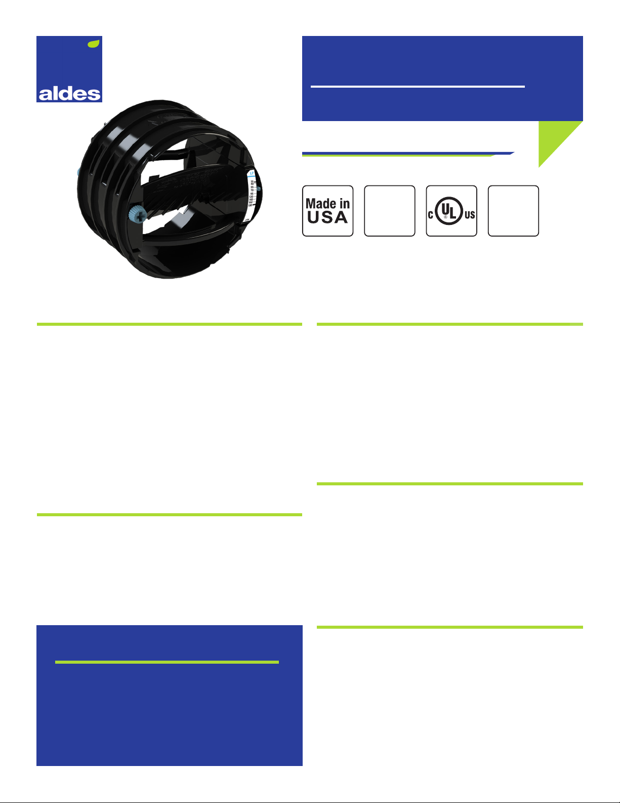
aldes VENTERGY BVS120 User manual

Product Description
ALDES North America Ventergy® Series IAQ-BVS kit includes lters and Constant Airow Regulators (CAR3®). The CAR3®
accurately balances the amount of fresh air brought into the house. The fresh air is then mixed and ltered with the
tempered air and distributed throughout the house. Blending/Filtering Ventilators are suitable for ALL ASHRAE Climatic
Zones. In extreme weather conditions, the ratio of inside air can be increased to oset temperature dierences.
VENTERGY®IAQ-BVS
RESIDENTIAL
SYSTEM
SOLUTIONS
BLENDING/FILTERING ACCESSORY KITS
For more information, contact your Aldes sales advisor, visit aldes-na.com, call 1.800.255.7749, or find us on
RECOMMENDED
FAN
Sold separately
ENERGY STAR
Certified* Ventilator
Airflow Regulators CAR3®*** Supply Air Return Air Intake
5”
CAR3®
(35-180 CFM)
4”
CAR3®
(15-85 CFM)
6”
Algrille
6”
Universal
Sleeve
6”
Backdraft
Damper
6”
Wye
4”
Deco
Grille
4”
Universal
Sleeve w/
Backdraft
Damper
4”
Wye
5”
Wall
Hood
BVS120 1 2 1 1 1 -- 2 2 -- 1
BVS200 1 3 2 2 2 1 3 3 -- 1
SPEC & IOM
1. RETURN AIR – All 4” Deco Grilles
and sleeves are designed for ceiling
installation. Installation in walls
will require special spring-loaded
backdraft dampers.
2. SUPPLY AIR – All 6” supply grilles
(Algrilles) and corresponding universal
sleeves are designed for ceiling
installation. The 6” Spring-Loaded
Backdraft Dampers should be inserted
into the Universal Sleeves by the
installer and positioned so that the
damper blades open downward.
3. OUTSIDE/FRESH AIR – A 5” low-
pressure Wall Hood with debris screen
is provided as an intake for outside
air. It should be located at least 18”
above the ground or snow line. While
generally not required, a 5” backdraft
damper can be ordered for installation
in the wall hood collar. Contact the
factory for assistance.
4. CONSTANT AIRFLOW REGULATORS
(CAR3®) are provided in each BVS
fan for automatic balancing of fresh,
return, and supply air. They are located
in the BVS duct-attachment collars.
FRESH AIR FROM
OUTSIDE
FILTERED/TEMPERED AIR
TO LIVING SPACE
BVS120 or BVS200
RETURN AIR
RETURN AIR
4" WYE
6" WYE
6" UNIVERSAL SLEEVE
6" ALGRILLE
4" DECO
GRILLE
4" UNIVERSAL SLEEVE
W/BACKDRAFT
DAMPER
4" UNIVERSAL SLEEVE
W/BACKDRAFT
DAMPER
4" DECO
GRILLE
5" WALL HOOD
4"CAR3®
5" CAR3®
IAQ-BVS_KIT_SPEC & IOM. ©2021 American ALDES Ventilation Corporation and ALDES Canada. All Rights Reserved. Reproduction or distribution, in whole or in part, of this document, in any form or by any means,
without the express written consent of American ALDES Ventilation Corporation and/or ALDES Canada, is strictly prohibited. The information contained within this document is subject to change without prior written notice.

Product Description
The Aldes CAR3 Constant Airflow Regulator is a pressure
independent balancing damper that automatically regulates
airow in duct systems to constant levels. The CAR3 requires
no electric or pneumatic power or sensors, and works solely o
system pressure.
Unlike traditional manual dampers, the CAR3 compensates
for changes in duct pressure caused by stack eect, operable
windows and doors, wind, loading lters, etc. The CAR3 provides
a low-cost solution to maintaining the correct airow balance of
ventilation systems, improving system performance and indoor
air quality, which can provide significant savings on annual
operating costs.
Key Features
• Dual-side airow adjustment dial and CFM indicator allows
you to set or change the airow quickly, in supply or exhaust
applications, without removing the CAR3 from the duct.
• Modulating rotary damper automatically responds to
changes in duct pressure to maintain set ow.
• Resin is enhanced with antimicrobial, anti-static, and ame
retardant additives for increased safety and durability.
CAR3
AIRFLOW & ZONE CONTROL
WARRANTY
7 YEARS
Patent
pending
CONSTANT AIRFLOW REGULATOR
Construction
• CAR3 constructed of amorphous thermoplastic resin
enhanced with antimicrobial, anti-static, and ame retardant
additives to improve material performance, reduce need for
maintenance, and increase safety.
• CAR3 is UL 2043 safety classied and labeled for ame and
smoke generation (File No. R39897).
• Double lip gasket around the circumference ensures a tight,
no-leak t.
Maintenance
The CAR3 needs no maintenance when used in normal
conditions. The addition of antimicrobial and anti-static
additives in the material increases the longevity and reliability
of the CAR3. There is no risk of dust deposit or obstruction
because the CAR3 has no airways subject to clogging. If the
intended application includes air heavily loaded with dust or
grease, access to the CAR3 will be possible through the terminal
device or with an access panel or door.
Warranty
Guaranteed for 7 years, from date of shipment, against all
defects in material or workmanship, provided that the material
has been installed and used under normal conditions. This
warranty is limited to the repair or replacement of the material.
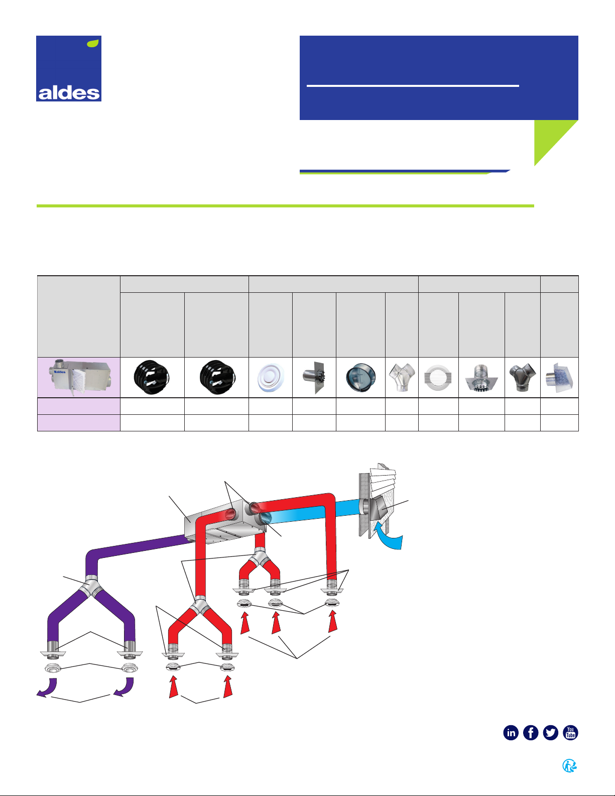
APPLICATIONS
• Automatic balancing of round duct.
• Balance supply or exhaust/return duct in high-rise
building.
• Sized to t inside standard rigid round ducting,
take-os, tees, and more.
• New construction or retrot.

CAR3-L4-R4
PARENT MODEL
Constant Airow Regulator
PRESSURE RANGE
L: Low-Pressure (0.12-1.2 in. w.g.)
H: High-Pressure (0.4-2.8 in. w.g.)
AIRFLOW RANGE
Low Pressure
4: 15-85 CFM (25-144 m3/h)
5: 35-180 CFM (59-306 m3/h)
6: 45-260 CFM (76-442 m3/h)
High Pressure
4: 30-160 CFM (51-272 m3/h)
5: 55-260 CFM (93-442 m3/h)
6: 60-370 CFM (102-629 m3/h)
ROUND DUCT SIZE
R4: 4 inch
R5: 5 inch
R6: 6 inch
Model Code Example
Page 2 | CAR3
Duct Size A ØB
R4 = 4˝
(100 mm)
3˝
(78 mm)
4.3˝
(108 mm)
R5 = 5˝
(125 mm)
3.8˝
(97 mm)
5.2˝
(132 mm)
R6 = 6˝
(150 mm)
4.6˝
(118 mm)
6.0˝
(153 mm)
CAR3 Dimensions
Ø B A
FRONT VIEW SIDE VIEW
How to Specify Aldes: CAR3
Step 1: Reference the model code below and performance details within this specications sheet to select the appropriate CAR3.
Step 2: Determine the required PRESSURE RANGE for the CAR3 based on the anticipated external static pressure of the system at
the installed CAR3 location.
NOTE: The CAR3-L (low-pressure) is designed for systems with pressures between 0.12 and 1.2 in. w.g. (30 to 300 Pa), and
CAR3-H (high-pressure) between 0.4 and 2.8 in. w.g. (100 to 700 Pa).
Step 3: Select the desired AIRFLOW RANGE.
NOTE: Ranges available: 4, 5, or 6. Each has a unique range for both low- and high-pressure variants.
See Airow Settings and Performance Data for additional details. Factory calibration of the CAR3 is available on request.
Step 4: Select the ROUND DUCT SIZE.
NOTE: This number cannot be less than the AIRFLOW RANGE: i.e. an airow range of 5 requires a duct size of 5 or 6
inches, R5 or R6 respectively.

ADJUSTMENT DIAL
AIRFLOW INDICATOR
CAR3 4" DIAMETER (100 mm)
CAR3 5" DIAMETER (125 mm)
CAR3 6" DIAMETER (150 mm)
40
30
20
10
50
60
70
80
90
100
0.200.12 0.40 0.60 0.80 1.0 1.20
50
CFM
m
3
/h
0
70
50
35
15
85
100
120
135
150
170
0
0
0
Pa
CAR3L4
in w.g.
100 150 200250 30030
25 CFM
15 CFM
45 CFM
35 CFM
65 CFM
55 CFM
85 CFM
75 CFM
80
60
40
20
100
120
140
160
180
200
0.500.40 1.01.502.0 2.50 3.0
125
CFM
m
3
/h
0
135
100
70
35
170
205
240
270
305
340
0
0
0
Pa
CAR3H4
in w.g.
250 375 500 625750100
45 CFM
30 CFM
80 CFM
60 CFM
120 CFM
100 CFM
160 CFM
140 CFM
100
50
150
200
250
0.20 0.40 0.60 0.80 1.0 1.20
50
CFM
m
3
/h
0
170
85
255
340
425
0
0
0
Pa
CAR3L5
in w.g.
100 150 200250 30030
40 CFM
35 CFM
70 CFM
55 CFM
120 CFM
95 CFM
160 CFM
180 CFM
140 CFM
0.12
CAR3H5
100
50
150
200
250
300
0.50 1.0 1.502.0 2.50 3.0
125
CFM
m
3
/h
0
255
170
85
340
425
510
0
0
0
Pa
in w.g.
250 375 500625 750
65 CFM
55 CFM
100 CFM
80 CFM
160 CFM
130 CFM
230 CFM
260 CFM
200 CFM
0.40
100
0.20 0.40 0.60 0.80 1.0 1.20
50
Pa
100 150 200250 30030
0.12
CFM
m
3
/h
CAR3L6
in w.g.
100
50
150
200
250
300
0
255
170
85
340
425
510
0
0
0
70 CFM
55 CFM
45 CFM
105 CFM
85 CFM
155 CFM
130 CFM
225 CFM
260 CFM
185 CFM
CFM
m
3
/h
0 0
Pa
CAR3H6
in w.g.
150 CFM
125 CFM
100 CFM
75 CFM
60 CFM
235 CFM
190 CFM
325 CFM
275 CFM
370 CFM
0.50 1.0 1.502.0 2.50 3.0
125
0
0 250 375 500625 750
0.40
100
100
50
150
200
250
300
350
400
450
170
85
255
340
425
510
595
680
765
Low-Pressure High-Pressure
Page 3 | CAR3
Airow Settings & Performance Data
Airow rate can be set or adjusted by rotating the dial from either side. The airow indicator
will move to show the selected CFM. The airow label has multiple dened setpoints, but
the unique adjustment mechanism of the CAR3 allows for innite adjustability between the
minimum and maximum limits.
Performance charts found in the specications sheet reect this data, with the available
range (shaded) and marked setpoints (lines). The CAR3 will maintain the airow accurately
to within +/- 10% of the indicated lines below for each marked setpoint. At the higher
airow rates, the minimum pressure required to achieve the selected airow may exceed
0.12 in. w.g.
Airow measurements taken at 68°F (20°C) at 1 atmosphere pressure.

Page 4 | CAR3
©2020 American ALDES Ventilation Corporation and ©2020 ALDES Canada. CAR3_SPEC_0620. Aldes reserves the right to modify its products at any time to introduce new technologies.
For more information, contact your Aldes sales advisor, visit aldes-na.com, call 1.800.255.7749, or find us on
Recommended Specication
Model CAR3 Constant Airow Regulator by ALDES North America shall capable of maintaining constant airow within +/-10% of
the scheduled ow rates, within the operating range of 0.12 to 1.2 in. w.g. dierential pressure for low-pressure models (CAR3-L), or
0.4 to 2.8 in. w.g. with high-pressure models (CAR3-H). CAR3 solely operate on duct pressure and require no external power supply
or sensors, and shall be rated for use in air temperatures ranging from -25°F to 140°F (-32°C to 60°C). CAR3 must be equipped with
double lip gasket to provide a secure, leak free installation into rigid round duct, take-os, collars, etc. Each regulator shall feature
dual-side adjustment dial to allow changes in airow setpoint while installed in either the supply or exhaust direction without
removing the regulator from the duct. Each CAR3 must be calibrated to match the airows indicated on the schedule or drawings.
Regulator must be classied per UL 2043 and carry the UL mark indicating compliance. Constant Airow Regulator is enhanced
with antimicrobial, anti-static, and ame retardant additives for increased durability and safety, and covered under warranty for a
period of no less than seven years. Constant Airow Regulator shall be installed in accordance with local code and manufacturer’s
instructions.

www.aldes-na.com
CAR3
Constant Airflow Regulator
Installation Operation Maintenance
EN

2
1. AIRFLOW SETTING
Airow rate can be set or adjusted by rotating the dial from either side. The airow indicator will move
to show the selected CFM. The airow label has multiple dened setpoints, but the unique adjustment
mechanism of the CAR3 allows for innite adjustability between the minimum and maximum limits.
Performance charts found in the specications sheet reect this data, with the available range (shaded)
and marked setpoints (lines). The CAR3 will maintain the airow accurately to within +/- 10% of the
indicated lines below for each marked setpoint. At the higher airow rates, the minimum pressure
required to achieve the selected airow may exceed 0.12 in. w.g.
Each diameter has a unique range for both low- and high-pressure variants. The CAR3-L (low-pressure)
is designed for systems with pressures between 0.12 and 1.2 in. w.g. (30 to 300 Pa), and CAR3-H (high-
pressure) between 0.4 and 2.8 in. w.g. (100 to 700 Pa). Factory calibration of the CAR3 is available on
request. Blue color dial = Low-Pressure / Green color dial = High-Pressure.
ADJUSTMENT DIAL
AIRFLOW INDICATOR
2. DIMENSIONS
Ø B A
Size A Ø B
Low-Pressure (Blue)
0.12-1.2 in. w.g
(30-300 Pa)
High-Pressure (Green)
0.4-2.8 in. w.g
(100-700 Pa)
Airflow P/N Airflow P/N
4'' (100 mm) 3’’ 4.3’’ 15-85 CAR3L4R4 30-160 CAR3H4R4
5'' (125 mm) 3.8’’ 5.2’’ 35-180 CAR3L5R5 55-260 CAR3H5R5
6'' (150 mm) 4.6’ 6.0’’ 45-260 CAR3L6R6 60-370 CAR3H6R6

3
3. INSTALLATION
Rigid Duct
or Register
Box
CAR3
Duct Collar
DL ≥ 1.2 D
Flex Duct
Flex Duct
CAR3
Duct Collar
or Grille
D
L ≥ 1.2 D
Duct Collar
The CAR3 should be installed in accordance with all applicable building and mechanical codes. If
installed in a metal duct or duct collar with a exible duct connector (listed to UL 2043), the CAR3 must
be inserted at least 1.2 times the duct diameter from the exible duct and/or duct connector.
Orient the CAR3 according to the airow direction
indicated on the device. Horizontal or vertical mounting
is acceptable.
3
6
0
°
Regulator must be installed in a metallic air duct as pictured above. D represents the regulators
maximum outer diameter.
Minimum
1.2 x D
Minimum
1.2 x D
D

www.aldes-na.com
CAR3 IOM_USA. 0620
©2020 American ALDES Ventilation Corporation and ©2020 ALDES Canada. Reproduction or distribution, in whole or in part, of
this document, in any form or by any means, without the express written consent of American ALDES Ventilation Corporation, is
strictly prohibited. The information contained within this document is subject to change without prior written notice.
Aldes North America
USA 800.255.7749 • CAN 800.262.0916 • www.aldes-na.com
5. TROUBLESHOOTING
PROBLEM CAUSE SOLUTION
AIRFLOW TOO LOW
Insufficient duct pressure. Check fan ratings. Replace fan if too small
Increase fan speed.
Excessive duct air leakage. Seal ducts with mastic or tape.
CAR3 damper
not functioning properly.
Check CFM calibration on CAR3.
Adjust to proper airflow value.
AIRFLOW TOO HIGH
AND/ OR NOISY
OPERATION
CAR3 too close to fan. Add manual damper to reduce pressure
across CAR3 to normal operating range.
Fan at too high a speed. Lower fan speed.
CAR3 damper
not functioning properly.
Check CFM calibration on CAR3.
Adjust to proper airflow value.
4. MAINTENANCE & WARRANTY
• The CAR3 needs no maintenance when used in normal conditions. The addition of antimicrobial and
anti-static additives in the material increases the longevity and reliability of the CAR3. There is no risk
of dust deposit or obstruction because the CAR3 has no airways subject to clogging. If the intended
application includes air heavily loaded with dust or grease, access to the CAR3 should be possible
through the terminal device or with an access panel or door.
• ALDES Ventilation Corporation warrants the CAR3 to be free from manufacturing defects and
guarantees the performance within specied limits for a period of seven (7) years when installed in
normal environmental air systems for general residential and commercial heating, ventilating and air
conditioning. This warranty does not include installation in industrial
applications or caustic, noxious
or otherwise hazardous airhandling equipment. This warranty
is limited to replacement of the product
only and does not extend to consequential claims.

Algrilles
• Supply/Exhaust
• Available in 3”, 4”, 5”, 6”, & 8”
• Fully adjustable for variable airow capacity
• Rotating center-adjustment cone
• Easy to install
• Durable white plastic (polypropylene co-polymer with
HB UL rating)
How to use
The center adjustment cone allows for variable ventilation
capacity.
After installing your Algrille vents and connecting them to the
ductwork from your ventilator, begin balancing the ventilation
ports by increasing openings on the most distant Algrille until the
ow is satisfactory throughout the building. Usually 2 rounds of
balancing will provide the desired air distribution.
Installation
Compression-spring tab clips the Algrille into 4”, 5”, 6”, or 8”round
duct.
ALGRILLES
ROOF CAPS, WALL HOODS, GRILLES
& DUCT FITTINGS
SUPPLY/EXHAUST GRILLES
Foam for tight seal and sound attenuation.
PRESSURE DROP INCHES W.C.
ALGRILLE FLOW SPECIFICATIONS AND PERFORMANCE GRAPH
FULLY OPEN
CFM
0.24
0.20
0.16
0.12
0.08
0.04
0.00
030 90 120 150 180 210 240 270 30060
4" 5" 6"
8"
©2020 American ALDES Ventilation Corporation and ©2020 ALDES Canada. Algrilles_SPEC_1020. Aldes reserves the right to modify its products at any time to introduce new technologies.
For more information, contact your Aldes sales advisor, visit aldes-na.com, call 1.800.255.7749, or find us on
C
A
B
D
P/N SIZE A B C D
40 103 3” 2-7/8” 1” 1” to 1-7/8” 4-5/8”
40 104 4" 3-1/4” 1” 1-7/8" to 3-1/4” 5-7/8”
40 105 5" 3-1/2” 1-1/4” 2" to 3-1/4” 6-1/4”
40 106 6" 4-11/16” 1” 1-3/4" to 3-1/4” 7-1/2”
40 108 8" 6 -3/4” 1-3/4” 2-1/2" to 3-3/4” 9-5/8”
Dimensional Data

UNIVERSAL SLEEVES
ROOF CAPS, WALL HOODS, GRILLES
& DUCT FITTINGS
FOR CONNECTING GRILLES TO FLEX DUCT WORK
©2020 American ALDES Ventilation Corporation and ©2020 ALDES Canada. Universal Sleeves_SPEC_1020. Aldes reserves the right to modify its products at any time to introduce new technologies.
For more information, contact your Aldes sales advisor, visit aldes-na.com, call 1.800.255.7749, or find us on
Dimensional Data
PART NUMBER DESCRIPTION Dia.
AB C Dia.
D
Dia.
E
Dia.
FG H
22 094 4” Dia. Sleeve 9” 5-1/2” 7” x 9” 5” 4-1/8” 4” 1/2” 1”
22 095 5” Dia. Sleeve 10” 5” 8”x 10” 5-3/4” 5-1/8” 4-15/16” 1/2” 1”
22 096 6” Dia. Sleeve 11” 5-1/2” 9”x 11” 7” 6” 5-7/8” 1/2” 1”
22 098 8” Dia. Sleeve 11” 7-1/4” 11” x 11” 9-1/8” 8-1/8” 8” 1/2” 1”
C
A
B
D
E
F
GH

Product Description
• 20-gauge galvanized steel housing.
• Aluminum spring-loaded buttery damper blades.
• Damper seals against EDPM rubber gasket in closed
position for minimal leakage.
• Gasket designed for use in temperatures from -22°F
to180°F.
• Requires airows of 0.04 to 0.08 in. w.g. to begin to
open.
• May be installed in any position. The 14” and 16”
models require adjusting spring tension if used in
vertical position, with airow down.
• The entire assembly inserts into duct for simple
installation.
• Exterior rubber seal (4”, 5”, 6”) or foam gaskets (7”+)
provide a tight seal against interior surface of duct.
BACKDRAFT DAMPERS
SPRING-LOADED BACKDRAFT DAMPERS
NOTE: Not recommended for use with clothes dryer, unless proper
provisions are made for regular cleaning. For this application, request
P/N 99 504, 4" diameter cape backdraft damper.
NOTE: Position of post in sleeve and number of springs varies
according to model.
Center
C
PART NUMBER NOMINAL A B C
99 023 4” (100 mm) 1-3/4" 2" 3-3/4"
99 024 5” (125 mm) 2" 2-1/2" 4-3/4"
99 025 6” (150 mm) 2-1/2" 3" 5-3/4"
99 035 7” (175 mm) 2-1/2" 3-1/4" 6-3/4"
99 026 8” (200 mm) 2-3/4" 3-3/4" 7-9/16"
99 027 10” (250 mm) 4-3/4" 5-3/4" 9-3/4"
99 028 12” (315 mm) 6-1/4" 6-3/4" 11-3/4"
99 036 14” (355 mm) 6-1/4" 7-3/4" 13-3/4"
99 037 16” (400 mm) 6-1/4" 10-3/4" 15-3/4"
AIRFLOW & ZONE CONTROL
Dimensional Data
4" - 7" MODELS
STAMPED METAL SLEEVE / CENTER PIN DESIGN
8" - 16" MODELS
ROLLED METAL SLEEVE / CENTER POST DESIGN

©2020 American ALDES Ventilation Corporation and ©2020 ALDES Canada. Backdraft Dampers_SPEC_1020. Aldes reserves the right to modify its products at any time to introduce new technologies.
For more information, contact your Aldes sales advisor, visit aldes-na.com, call 1.800.255.7749, or find us on
Page 2 | BACKDRAFT DAMPERS
Airow Performance

WYES
ROOF CAPS, WALL HOODS, GRILLES
& DUCT FITTINGS
4"- 10"
©2020 American ALDES Ventilation Corporation and ©2020 ALDES Canada. WYES_SPEC_1020. Aldes reserves the right to modify its products at any time to introduce new technologies.
For more information, contact your Aldes sales advisor, visit aldes-na.com, call 1.800.255.7749, or find us on
Dimensional Data
PART NUMBER DIA. A DIA. B DIA. C
93 081 4” 3” 3”
93 082 4” 4” 4”
93 087 5” 4” 4”
93 083 5” 5” 5”
93 086 6” 4” 4”
93 085 6” 5” 5”
93 084 6” 6” 6”
93 090 8” 8” 8”
93 091 8” 6” 6”
93 094 10” 10” 10”
93 095 10” 8” 8”
A
CB

DECO GRILLES
ROOF CAPS, WALL HOODS, GRILLES
& DUCT FITTINGS
WHITE PLASTIC GRILLES
©2020 American ALDES Ventilation Corporation and ©2020 ALDES Canada. DECO GRILLES_SPEC_1020. Aldes reserves the right to modify its products at any time to introduce new technologies.
For more information, contact your Aldes sales advisor, visit aldes-na.com, call 1.800.255.7749, or find us on
Dimensional Data
PART NUMBER SIZE DESCRIPTION A B C D E F
22 073 3" White Plastic ABS Grille 3" 4-3/4" 1/2" 5/8" 1-7/8” 4-3/4”
22 079 4" White Plastic ABS Grille 3-7/8" 5-3/4" 11/16" 1" 2-1/2” 6-1/4”
22 078 5" White Plastic ABS Grille 4-7/8" 6-1/2" 5/8" 1-1/4" 3-1/8” 7-3/4”
A
F
E
C
B
D
A
F
E
C
B
D

UNIVERSAL SLEEVES
ROOF CAPS, WALL HOODS, GRILLES
& DUCT FITTINGS
WITH GRAVITY BACKDRAFT DAMPERS
©2020 American ALDES Ventilation Corporation and ©2020 ALDES Canada. Universal Sleeves with BDD_SPEC_1020. Aldes reserves the right to modify its products at any time to introduce new technologies.
For more information, contact your Aldes sales advisor, visit aldes-na.com, call 1.800.255.7749, or find us on
Dimensional Data
PART NUMBER DESCRIPTION Dia.
AB C Dia.
D
Dia.
E
Dia.
FG H
22 194 4” Dia. Sleeve 9” 5-1/2” 7” x 9” 5” 4-1/8” 4” 1/2” 1”
22 195 5” Dia. Sleeve 10” 5” 8” x 10” 5-3/4” 5-1/8” 4-15/16” 1/2” 1”
22 196 6” Dia. Sleeve 11” 5-1/2” 9” x 11” 7” 6” 5-7/8” 1/2” 1”
C
A
B
D
E
F
GH

Product Description
Aldes High-Performance Wall Hoods are designed for use in
exhaust or supply ventilation systems and fresh air kits. They
are engineered to accommodate high airow pressure and
velocities found in premium fan and dryer vent systems. Wall
hoods are available as screened or dampered versions. Each
wall hood is designed to maximize airow and minimize noise.
Construction
Wall Hoods are available in heavy-gauge G90 galvanized
steel.
Screened Wall Hoods
1/4” galvanized steel mesh. Suitable for use in exhaust or
supply ventilation systems and fresh-air kits.
Dampered Wall Hoods
For use in exhaust ventilation and dryer venting systems. A
magnetic-catch damper ensures a tight closure when the fan is
not running and eliminates damper utter in windy conditions.
These hoods should be used when backdraft dampers are not
present at other locations within the duct system.
Dimensions
HIGH-PERFORMANCE
WALL HOODS
ROOF CAPS, WALL HOODS, GRILLES
& DUCT FITTINGS
WITH SCREENS OR GRAVITY DAMPERS
©2020 American ALDES Ventilation Corporation and ©2020 ALDES Canada. HP_WallHoods_SPEC_0920. Aldes reserves the right to modify its products at any time to introduce new technologies.
For more information, contact your Aldes sales advisor, visit aldes-na.com, call 1.800.255.7749, or find us on
MODEL Galvanized** Dimensions
Dampered* Screened
Size P/N P/N A B C D E F
4" 22 404 22 304 4” 3” 3.0” 4.5” 8” 6”
5" 22 405 22 305 5” 3” 3.0” 5.0” 9” 8”
6" 22 406 22 306 6” 3” 4.0” 6.0” 10” 9”
8" 22 408 22 308 8” 3” 5.0” 8.0” 12” 11”
10" 22 410 22 310 10” 3” 6.5” 10.0” 14” 13”
12" 22 412 22 312 12” 3” 8.5” 12.0” 16” 15”
*For wall hoods with screens and backdraft dampers, add backdraft damper to screen model.
**Galvanized Steel Items (4” to 8” are 26 gauge; 10” and 12” are 24-gauge).
Materials: Galvanized Steel G-90. Damper: Aluminum sheet, 0.020”
C
AE
B
DF
With Damper With Screen

Product Description
Ventergy® Series Ventilator Fans represent years of engineering
development to combine the energy eciency and sound performance
of a forward-curved fan with the durability and pressure characteristics
of a backward-inclined impeller fan.
BVS Series Blending Ventilators are highly versatile, continuous-duty
ratedunitsforresidentialapplications.Theymeet ENERGYSTAReciency
criteria for low energy consumption. The BVS is designed to provide
fresh outdoor air and blend it with indoor air drawn from bedrooms or
areas typically not served by a central thermostat before ltering and
distributingthis airto themain living areasofthe home.Thermalcomfort
isenhancedbecausewarmer airis drawnnaturallyfromthe heatedliving
areas to the cooler bedrooms.
The BVS is designed to lter both indoor and incoming fresh air and
prevent the introduction of contaminants as a result of unwanted
infiltration through leaks in the building’s envelope. By slightly
pressurizing the structure, the BVS also reduces the risk of backdrafting
heatingappliances,waterheaters,andreplaces.Quiet,continuous-duty,
energy-ecient,external-rotormotorswithpermanentlysealedbearings
provide many years of maintenance-free performance.
Construction
BVS series fans are constructed of heavy-gauge galvanized steel to
prevent corrosion caused by moisture. The cabinet is internally lined
withacoustic, closed-cell foaminsulation that acts as a vaporbarrier.This
allowsforinstallationdirectly aboveliving spacesor inunheatedplenum
spaces without concern for noise or condensation. Duct connecting
collars may be relocated on the fan intake manifold to accommodate
dierent installation requirements.
Fan Controls
The fan can be operated manually or automatically by a programmable
timer, dehumidistat, or other appropriate electronic switch device. The
fan may also be operated in conjunction with a variable speed control.
BVS120 & BVS200
VENTERGY®SERIES FANS
WARRANTY
3 YEARS
BLENDING/FILTERING VENTILATORS
Fan and Motor
The fan motor is an energy-ecient, permanent-split-capacitor type
of external-rotor design. Totally sealed to protect against moisture and
contaminants,itincorporatespermanentlylubricatedandsealedbearings
and automatic-reset thermal-overload protection. It is designed and
certied for continuous duty or intermittent operation.
The fan uses a backward-inclined impeller design that minimizes dust
collection on blades. Each fan is statically and dynamically balanced at
the factory to eliminate vibration and ensure quiet operation.The entire
motorandfan assemblyismountedon adrop-downhinged accesspanel
for simple service and inspection, and it can be removed from the fan
without disassembling the duct connections.
Filters
Each BVS comes standard with a disposable-type 1”pleated MERV 8 lter
to comply with ASHRAE 62.2 and ENERGY STAR standards. Permanent,
washable, electrostatic-type lters are also available.
Locating and Installing
The compact dimensions and versatile mounting options permit
installation above drop ceilings, between ceiling joists, or within a small
sot location. They can be installed horizontally or vertically.
Accessories
Accessorykitsareavailabletofacilitateinstallationandenhanceoperation.
Accessories kits are sold separately. Please visit aldes-na.com, or contact
your local Aldes distributor for details.
IOM
READ AND SAVE THESE INSTRUCTIONS

Page 2 | BVS120 & BVS200
WARRANTY
3 YEARS
Dimensions & Performance
NOTE: Dashed lines indicate eld installed side collar location
ELECTRICAL DATA
BVS120: 115 V, 60 Hz, 41 W, 0.34 A, 2200 RPM
BVS200: 115 V, 60 Hz, 59 W, 0.53 A, 2960 RPM
Above ratings are intended for sizing electrical wiring only.
Actual consumption will be lower.
Model
Watts
at 0.2"
Ps
CFM vs. Static Pressure ENERGY
STAR
Certied
0.0" 0.2" 0.4" 0.6" 0.8" 1.0"
BVS120 34.2 184 140 115 85 55 26
BVS200 56.6 247 220 192 164 136 101
*Certied airow rating at 0.2" w.g. is derated from actual test results per HVI Certication procedure 920.
The HVI Certied Rate for BVS120 = 140 CFM, BVS200 = 220 CFM.
ELECTRICAL AND AIRFLOW PERFORMANCE*
6"
12"
5"
5" 8"
2-1/2"
1-7/8"
26-1/2"
5"
8"
6"
1¾"
4"
4"
4"
HINGED FILTER ACCESS
4" 5"4" 4"8"
12"
6"
12"
5"
5" 8"
2-1/2"
1-7/8"
26-1/2"
5"
8"
6"
1¾"
4"
4"
4"
HINGED FILTER ACCESS
Internally
insulated
with
acoustic
vapor barrier
insulation
Heavy-gauge G90
galvanized steel
construction
MERV 8 pleated lter
or A+2000 electrostatic
permanent lter
options
Drop-down hinged
motor and lter access
panels for easy service
High-eciency motor
meets ENERGY STAR
performance criteria
BVS120 & BVS200 Components
SIDE VIEW
INTAKE END VIEW TOP VIEW

Page 3 | BVS120 & BVS200
©2020 American ALDES Ventilation Corporation. BVS120 & BVS200_IOM_1020. Aldes reserves the right to modify its products at any time to introduce new technologies.
For more information, contact your Aldes sales advisor, visit aldes-na.com, call 1.800.255.7749, or find us on
MAINTENANCE
Monthly: Clean the exhaust and supply grilles.
Seasonally: Clean the fresh air intake wall hood.
Ducting the Fan
Theducting fromthis fanto theoutside ofthe buildinghas astrong eect
ontheairow,noiseandenergyuseofthe fan.Usetheshortest,straightest
duct routing possible for best performance, and avoid installing the fan
with smaller ducts than recommended. Insulation around the ducts can
reduce energy loss and inhibit mold growth. Fans installed with existing
ducts may not achieve their rated airow.
Use ductwork of a diameter that is the same as or greater than the
diameter of the duct connectors on the fan.
Performance
Fan airow and energy performance are tested in accordance with HVI
procedures.
CEILING MOUNT
MOUNTING AGAINST WALL
MOUNTING ON ATTIC FLOOR OR SUSPENDED FROM CEILING
BVS120/BVS200 SCHEMATIC
*Sold separately
†Refer to IOM text for details
WALL HOOD
OR ROOF CAP*
FAN HOUSING
(Insulation may be installed
over the fan housing)†
Duct joints, and ceiling
and wall penetrations
should be sealed†
DUCTWORK*†
BACKDRAFT
DAMPER*†
SUPPLY GRILLE*
RETURN GRILLES*
RETURN GRILLE*
BACKDRAFT
DAMPERS*†
BACKDRAFT DAMPER*†
WARRANTY
3 YEARS
REFERENCE RDF INSTALLATION SUPPLEMENT FOR ADDITIONAL
INSTRUCTIONS AND WARRANTY INFORMATION.
This manual suits for next models
1
Table of contents
Other aldes Controllers manuals
Popular Controllers manuals by other brands

Holtek
Holtek HT46R62 Handbook

Chauvet
Chauvet Obey 70 user manual

Neptronic
Neptronic BT100S Specification & installation instructions

Sauter Components
Sauter Components flexotron 300 manual

Gopel Electronic
Gopel Electronic G CAR 6282 manual

elero
elero InDrive M30/1.6 RH Operating and assembly instructions